Embed Size (px)
Citation preview

Assembly Instructions – LeverOwned By: Robert Henry Rev: B
Description: This set of directions is a step by step on how to assembly the lever assembly.
Tools needed:- 3 mm Allen Wrench- Retaining Clip Pliers- Ratchet with 8mm socket
Sub-Assembly 1 (Aluminum Housing):Step 1: Using retaining clip pliers place a retaining clip on 1 of the gear shafts. Step 2: Slide one nylon washer onto the shaft and then slide one 23 teeth gear onto the shaft followed as shown in the following image.
Step 3: Place one more washer on the shaft and place a retaining clip to hold the gear in place. Step 4: Repeat steps 1-3 three more times.Step 5: Place one of the aluminum plates on the work surface so that the counterbores face up and insert the four spacers into the counterbores. Then place the one end of the shafts holding the ’23 teeth gear’ into the aluminum frame appropriately as seen in the following image.
Step 6: Place the 2nd aluminum plate onto the assembly with the counterbores facedown, aligning the spacers and gear shafts with the holes on the aluminum plate.
Step 7: Using a 3mm allen wrench insert four 5mm by ¾” length screws into the holes on the aluminum plate down into the spacers. Tighten until snug. Flip assembly and repeat on the remaining 4

holes. The assembly should look like the following image.
Sub-Assembly 2:Step 1: Place the bearing into the ring gear aligning the outer holes of the bearing with the holes of the ring gear. Step 2: Insert a 5mm by 1-7/8” inch bolt into each hole as shown in the following the image.
Step 3: Insert the aluminum housing assembly into the ring gear as shown in the following image.
Step 3: Place the steel ring on the ring gear aligning the holes with the bolts and placing a 5mm nut on each bolt. Tighten the nuts until snug by holding the screw head with a 3mm allen wrench and turning the nut with an 8mm socket.
Sub-Assembly 3: Step 1: After inserting the center gear into the cutout on the bottom of the top piece, place a bearing on the top plate and insert four 5 mm by 18 mm bolts into the holes of the

bearing through the top plate.
Step 2: Flip assembly over and place a nylon washer and nut onto each bolt and tighten until snug as shown in the following image.
Step 4: Place 3/8” bolt through the top plate, through the rubber clip, and then place a washer and nut on the bolt and tighten until snug.
Full Assembly:Step 1: Place a washer on a 3/8” bolt and insert from the top into the base plate. Repeat for each hole.
Step 2: Place a washer on the 3/8” bolt from the bottom and screw on the base clip as shown in the following image.
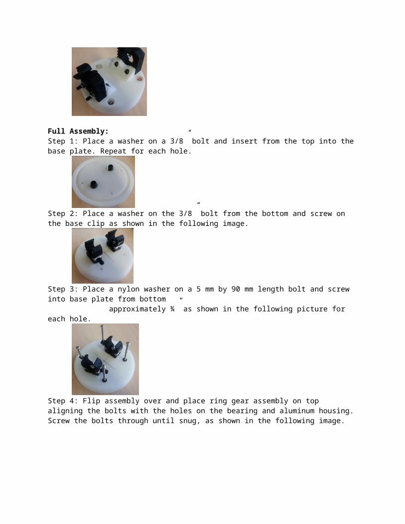
Step 3: Place a nylon washer on a 5 mm by 90 mm length bolt and screw into base plate from bottom approximately ¾” as shown in the following picture for each hole.
Step 4: Flip assembly over and place ring gear assembly on top aligning the bolts with the holes on the bearing and aluminum housing. Screw the bolts through until snug, as shown in the following image.
Step 5: Place the top gear assembly onto the full assembly aligning the black rubber clips to be parallel with the lever handle as shown in the following image. Note: to slide top gear on verify that the four 90 mm length bolt align with the holes of the top bearing and top gear plate.
Step 6: Align the access hole of the top gear plate with one of the 90 mm length bolts. Place a nut inside of the socket and tip assembly on its side as shown in the following image. Then begin tightening the nut onto the bolt. Note: you may need to set the assembly up while turning to start the nut onto the bolt. Tighten until snug. Rotate the top and repeat for each of the 4 bolts.