Embed Size (px)
Citation preview

Mellanox Technologies Confidentialwww.mellanox.com
648-Port EDR InfiniBand Switch-IB™ Series Switch Platform Hardware User ManualPN: CS7500 Rev 2.3
Doc #: 2190UG 2Mellanox Technologies Confidential
3Mellanox Technologies Confidential
Table of Contents
Revision History . . . . . . . . . . . . . . . . . . . . . . . . . . . . . . . . . . . . . . . . . . . . . . . 10About this Manual . . . . . . . . . . . . . . . . . . . . . . . . . . . . . . . . . . . . . . . . . . . . . . . 12Chapter 1 Overview . . . . . . . . . . . . . . . . . . . . . . . . . . . . . . . . . . . . . . . . . . . . 14
1.1 Product Information. . . . . . . . . . . . . . . . . . . . . . . . . . . . . . . . . . . . . . . . . . . 141.1.1 Serial Number and Product Version Information . . . . . . . . . . . . . . . . . . . . 141.1.2 Management Module MAC . . . . . . . . . . . . . . . . . . . . . . . . . . . . . . . . . . . . . 151.1.3 Product Physical Specifications and Power. . . . . . . . . . . . . . . . . . . . . . . . . 15
1.2 Features List . . . . . . . . . . . . . . . . . . . . . . . . . . . . . . . . . . . . . . . . . . . . . . . . . 171.3 InfiniBand EDR Overview . . . . . . . . . . . . . . . . . . . . . . . . . . . . . . . . . . . . . . . 171.4 Power Supply Redundancy . . . . . . . . . . . . . . . . . . . . . . . . . . . . . . . . . . . . . 17
1.4.1 AC Source Requirements . . . . . . . . . . . . . . . . . . . . . . . . . . . . . . . . . . . . . . . 171.4.2 Power Redundancy . . . . . . . . . . . . . . . . . . . . . . . . . . . . . . . . . . . . . . . . . . . . 17
1.5 Fan Redundancy . . . . . . . . . . . . . . . . . . . . . . . . . . . . . . . . . . . . . . . . . . . . . . 18Chapter 2 Installation . . . . . . . . . . . . . . . . . . . . . . . . . . . . . . . . . . . . . . . . . . . 19
2.1 Installation Safety Warnings . . . . . . . . . . . . . . . . . . . . . . . . . . . . . . . . . . . . 192.2 Environmental and Safety Recommendations. . . . . . . . . . . . . . . . . . . . . . 232.3 Switch Components . . . . . . . . . . . . . . . . . . . . . . . . . . . . . . . . . . . . . . . . . . . 242.4 Unpacking the Switch System . . . . . . . . . . . . . . . . . . . . . . . . . . . . . . . . . . . 25
2.4.1 Verifying Crate Condition . . . . . . . . . . . . . . . . . . . . . . . . . . . . . . . . . . . . . . . 252.4.2 Opening the Chassis Crate . . . . . . . . . . . . . . . . . . . . . . . . . . . . . . . . . . . . . . 26
2.5 Physical Installation . . . . . . . . . . . . . . . . . . . . . . . . . . . . . . . . . . . . . . . . . . . 282.5.1 Installation Kit Parts . . . . . . . . . . . . . . . . . . . . . . . . . . . . . . . . . . . . . . . . . . . 292.5.2 Required Installation Tools. . . . . . . . . . . . . . . . . . . . . . . . . . . . . . . . . . . . . . 322.5.3 Installation Procedure. . . . . . . . . . . . . . . . . . . . . . . . . . . . . . . . . . . . . . . . . . 33
2.6 Ground Connections. . . . . . . . . . . . . . . . . . . . . . . . . . . . . . . . . . . . . . . . . . . 592.7 FRU Insertion and Extraction (Hot-Swappable) . . . . . . . . . . . . . . . . . . . . . 60
2.7.1 Power Supply Units . . . . . . . . . . . . . . . . . . . . . . . . . . . . . . . . . . . . . . . . . . . . 612.7.2 Leaf Modules . . . . . . . . . . . . . . . . . . . . . . . . . . . . . . . . . . . . . . . . . . . . . . . . . 622.7.3 Spine Modules . . . . . . . . . . . . . . . . . . . . . . . . . . . . . . . . . . . . . . . . . . . . . . . . 642.7.4 Fan Modules . . . . . . . . . . . . . . . . . . . . . . . . . . . . . . . . . . . . . . . . . . . . . . . . . 682.7.5 Management Module . . . . . . . . . . . . . . . . . . . . . . . . . . . . . . . . . . . . . . . . . . 71
2.8 InfiniBand QSFP Cable Installation . . . . . . . . . . . . . . . . . . . . . . . . . . . . . . . 742.9 Cable Holder Placement. . . . . . . . . . . . . . . . . . . . . . . . . . . . . . . . . . . . . . . . 75
2.9.1 Supported Approved Cables. . . . . . . . . . . . . . . . . . . . . . . . . . . . . . . . . . . . . 752.9.2 Cable Power Classes . . . . . . . . . . . . . . . . . . . . . . . . . . . . . . . . . . . . . . . . . . . 76
2.10 Power Connections. . . . . . . . . . . . . . . . . . . . . . . . . . . . . . . . . . . . . . . . . . . . 76
4 Mellanox Technologies Confidential
Chapter 3 Interfaces . . . . . . . . . . . . . . . . . . . . . . . . . . . . . . . . . . . . . . . . . . . . 773.1 LED Status Indicators . . . . . . . . . . . . . . . . . . . . . . . . . . . . . . . . . . . . . . . . . . 77
3.1.1 Power Supply Unit LEDs . . . . . . . . . . . . . . . . . . . . . . . . . . . . . . . . . . . . . . . . 773.1.2 System AC Power Interface . . . . . . . . . . . . . . . . . . . . . . . . . . . . . . . . . . . . . 783.1.3 Leaf Module LED Indicators . . . . . . . . . . . . . . . . . . . . . . . . . . . . . . . . . . . . . 783.1.4 Spine Module LED Indicators . . . . . . . . . . . . . . . . . . . . . . . . . . . . . . . . . . . . 803.1.5 Spine Side Panel Display LED Indicators . . . . . . . . . . . . . . . . . . . . . . . . . . . 823.1.6 Management Module LED Indicators . . . . . . . . . . . . . . . . . . . . . . . . . . . . . 843.1.7 Port Connector Interfaces . . . . . . . . . . . . . . . . . . . . . . . . . . . . . . . . . . . . . . 85
3.2 Air Flow . . . . . . . . . . . . . . . . . . . . . . . . . . . . . . . . . . . . . . . . . . . . . . . . . . . . . 853.3 QSFP Cable Power Budget Classification . . . . . . . . . . . . . . . . . . . . . . . . . . 853.4 Management Module Interfaces. . . . . . . . . . . . . . . . . . . . . . . . . . . . . . . . . 85
3.4.1 I2C/Console (RS232) . . . . . . . . . . . . . . . . . . . . . . . . . . . . . . . . . . . . . . . . . . . 863.4.2 Management . . . . . . . . . . . . . . . . . . . . . . . . . . . . . . . . . . . . . . . . . . . . . . . . . 863.4.3 USB . . . . . . . . . . . . . . . . . . . . . . . . . . . . . . . . . . . . . . . . . . . . . . . . . . . . . . . . . 863.4.4 Reset – RST . . . . . . . . . . . . . . . . . . . . . . . . . . . . . . . . . . . . . . . . . . . . . . . . . . 86
Chapter 4 Chassis Power Up. . . . . . . . . . . . . . . . . . . . . . . . . . . . . . . . . . . . . . 884.1 System Status After Power Up . . . . . . . . . . . . . . . . . . . . . . . . . . . . . . . . . . 884.2 Switch Shut-Down Procedure . . . . . . . . . . . . . . . . . . . . . . . . . . . . . . . . . . . 89
Chapter 5 Switch Management Tools . . . . . . . . . . . . . . . . . . . . . . . . . . . . . . 905.1 InfiniBand Subnet Manager . . . . . . . . . . . . . . . . . . . . . . . . . . . . . . . . . . . . . 915.2 Fabric Inspector (Diagnostics) . . . . . . . . . . . . . . . . . . . . . . . . . . . . . . . . . . . 915.3 Accessing the CPU via the Ethernet Connector . . . . . . . . . . . . . . . . . . . . . 915.4 Upgrading Software . . . . . . . . . . . . . . . . . . . . . . . . . . . . . . . . . . . . . . . . . . . 91
Chapter 6 Troubleshooting. . . . . . . . . . . . . . . . . . . . . . . . . . . . . . . . . . . . . . . 926.1 Power Supply Unit . . . . . . . . . . . . . . . . . . . . . . . . . . . . . . . . . . . . . . . . . . . . 926.2 Leaf Module . . . . . . . . . . . . . . . . . . . . . . . . . . . . . . . . . . . . . . . . . . . . . . . . . 926.3 Management Module. . . . . . . . . . . . . . . . . . . . . . . . . . . . . . . . . . . . . . . . . . 936.4 Spine Module . . . . . . . . . . . . . . . . . . . . . . . . . . . . . . . . . . . . . . . . . . . . . . . . 946.5 MLNX-OS® Software . . . . . . . . . . . . . . . . . . . . . . . . . . . . . . . . . . . . . . . . . . . 94
Appendix A Specification Data . . . . . . . . . . . . . . . . . . . . . . . . . . . . . . . . . . . 96A.1 EMI Certification . . . . . . . . . . . . . . . . . . . . . . . . . . . . . . . . . . . . . . . . . . . 97A.2 Approved Cables . . . . . . . . . . . . . . . . . . . . . . . . . . . . . . . . . . . . . . . . . . . 98A.3 EMC Certifications . . . . . . . . . . . . . . . . . . . . . . . . . . . . . . . . . . . . . . . . . . 98
Appendix B Thermal Threshold Definitions . . . . . . . . . . . . . . . . . . . . . . . . . . 99Appendix C Calculating the Weight of a Customized Chassis . . . . . . . . . . . 100Appendix D Calculating the Power of a Chassis . . . . . . . . . . . . . . . . . . . . . . 101Appendix E QSFP Interface . . . . . . . . . . . . . . . . . . . . . . . . . . . . . . . . . . . . . . 102
5Mellanox Technologies Confidential
Appendix F MNG Console Interfaces . . . . . . . . . . . . . . . . . . . . . . . . . . . . . . 106Appendix G Replacement Parts Ordering Numbers . . . . . . . . . . . . . . . . . . . 107Appendix H Safety Warnings (Multiple Languages) . . . . . . . . . . . . . . . . . . . 108
H.1 Nordic Countries Notices . . . . . . . . . . . . . . . . . . . . . . . . . . . . . . . . . . . 108H.2 Installation Safety Warnings (English) . . . . . . . . . . . . . . . . . . . . . . . . . 108H.3 ( ( . . . . . . . . . . . . . . . . . . . . . . . . . . . . . 111H.4 (Chinese) . . . . . . . . . . . . . . . . . . . . . . . . . . . . . . . . . 114H.5 Avertissements de sécurité pour l'installation (French). . . . . . . . . . . 118H.6 Installation Sicherheitshinweise(German). . . . . . . . . . . . . . . . . . . . . . 121H.7 Advertencias de seguridad de instalación (Spanish) . . . . . . . . . . . . . 124H.8 Предупреждения по технике безопасности при установке (Russian) 127H.9 Avertismente privind siguranţa la instalare (Romanian) . . . . . . . . . . 130H.10 Sigurnosna upozorenja za instaliranje (Croatian) . . . . . . . . . . . . . . . . 134H.11 Avvertenze di sicurezza per l’installazione (italiano) . . . . . . . . . . . . . 137H.12 Montaj Güvenlik Uyarıları (Türkçe) . . . . . . . . . . . . . . . . . . . . . . . . . . . 141H.13 Japan VCCI Class A Statement . . . . . . . . . . . . . . . . . . . . . . . . . . . . . . . 144H.14
6 Mellanox Technologies Confidential
List of Tables
Table 1: User Manual Revision History. . . . . . . . . . . . . . . . . . . . . . . . . . . . . . . . . . . . . . . . . .10Table 2: Reference Documents and Websites . . . . . . . . . . . . . . . . . . . . . . . . . . . . . . . . . . . .12Table 3: Mellanox Part Number Legend. . . . . . . . . . . . . . . . . . . . . . . . . . . . . . . . . . . . . . . . .13Table 4: Power Supply OPN . . . . . . . . . . . . . . . . . . . . . . . . . . . . . . . . . . . . . . . . . . . . . . . . . . .18Table 5: Chassis Installation Kit Items. . . . . . . . . . . . . . . . . . . . . . . . . . . . . . . . . . . . . . . . . . .29Table 6: Cable Management Installation Kit Parts. . . . . . . . . . . . . . . . . . . . . . . . . . . . . . . . .31Table 7: Leaf Status LED. . . . . . . . . . . . . . . . . . . . . . . . . . . . . . . . . . . . . . . . . . . . . . . . . . . . . .79Table 8: Bad Port LED Configurations . . . . . . . . . . . . . . . . . . . . . . . . . . . . . . . . . . . . . . . . . . .79Table 9: Connector Physical and Logical Link Indications . . . . . . . . . . . . . . . . . . . . . . . . . . .79Table 10: Spine Status LED. . . . . . . . . . . . . . . . . . . . . . . . . . . . . . . . . . . . . . . . . . . . . . . . . . . . .81Table 11: Spine Fan Status LED . . . . . . . . . . . . . . . . . . . . . . . . . . . . . . . . . . . . . . . . . . . . . . . . .81Table 12: Spine to Leaf IB Link Status . . . . . . . . . . . . . . . . . . . . . . . . . . . . . . . . . . . . . . . . . . . .81Table 13: Bad Port LED Configurations . . . . . . . . . . . . . . . . . . . . . . . . . . . . . . . . . . . . . . . . . . .82Table 14: Spine-Side Panel LED Display for Normal Operation . . . . . . . . . . . . . . . . . . . . . . .83Table 15: Management LED Display for Normal Operation . . . . . . . . . . . . . . . . . . . . . . . . . .84Table 16: Switch Specification CS7500 . . . . . . . . . . . . . . . . . . . . . . . . . . . . . . . . . . . . . . . . . . .96Table 17: Switch System Weight Calculation . . . . . . . . . . . . . . . . . . . . . . . . . . . . . . . . . . . . .100Table 18: Power Consumption of Chassis Parts . . . . . . . . . . . . . . . . . . . . . . . . . . . . . . . . . . .101Table 19: QSFP Cable Power Consumption . . . . . . . . . . . . . . . . . . . . . . . . . . . . . . . . . . . . . .101Table 20: Calculating Total Switch System Power Consumption . . . . . . . . . . . . . . . . . . . . .101Table 21: InfiniBand QSFP Connector Pin-out . . . . . . . . . . . . . . . . . . . . . . . . . . . . . . . . . . . .102Table 22: RJ-45 CONSOLE and I²C Pinout . . . . . . . . . . . . . . . . . . . . . . . . . . . . . . . . . . . . . . . .106Table 23: Replacement Parts Ordering Numbers . . . . . . . . . . . . . . . . . . . . . . . . . . . . . . . . .107
7Mellanox Technologies Confidential
List of Figures
Figure 1: Product Label . . . . . . . . . . . . . . . . . . . . . . . . . . . . . . . . . . . . . . . . . . . . . . . . . . . . . . . . . . .14Figure 2: Product Label Tab Location . . . . . . . . . . . . . . . . . . . . . . . . . . . . . . . . . . . . . . . . . . . . . . . . .15Figure 3: Management Module MAC Address Location . . . . . . . . . . . . . . . . . . . . . . . . . . . . . . . . . .15Figure 4: CS7500 . . . . . . . . . . . . . . . . . . . . . . . . . . . . . . . . . . . . . . . . . . . . . . . . . . . . . . . . . . . . . . . . . .16Figure 5: Shock Stickers . . . . . . . . . . . . . . . . . . . . . . . . . . . . . . . . . . . . . . . . . . . . . . . . . . . . . . . . . . . .26Figure 6: Crate Screws . . . . . . . . . . . . . . . . . . . . . . . . . . . . . . . . . . . . . . . . . . . . . . . . . . . . . . . . . . . . .27Figure 7: Distance Between the Vertical Supports . . . . . . . . . . . . . . . . . . . . . . . . . . . . . . . . . . . . . . .28Figure 8: Chassis Installation Kit . . . . . . . . . . . . . . . . . . . . . . . . . . . . . . . . . . . . . . . . . . . . . . . . . . . . . .30Figure 9: Cable Management Installation . . . . . . . . . . . . . . . . . . . . . . . . . . . . . . . . . . . . . . . . . . . . . .31Figure 10: Shelf Installation Kit . . . . . . . . . . . . . . . . . . . . . . . . . . . . . . . . . . . . . . . . . . . . . . . . . . . . . . . .32Figure 11: Tools for Installation . . . . . . . . . . . . . . . . . . . . . . . . . . . . . . . . . . . . . . . . . . . . . . . . . . . . . . .32Figure 12: Cage Nut Placement for Shelf on BEAM-1 and BEAM-2 . . . . . . . . . . . . . . . . . . . . . . . . . . .33Figure 13: Cage Nut Placement for Shelf on BEAM-3 and BEAM-4 . . . . . . . . . . . . . . . . . . . . . . . . . . .34Figure 14: Cage Nut Placement for Support Bracket . . . . . . . . . . . . . . . . . . . . . . . . . . . . . . . . . . . . . .35Figure 15: Cage Nut Placement for Switch System Chassis on Spine Side . . . . . . . . . . . . . . . . . . . . .36Figure 16: Cage Nut Placement for Cable Holders on Leaf Side . . . . . . . . . . . . . . . . . . . . . . . . . . . . .37Figure 17: Loosening the Leaf-Side Shelf Arms . . . . . . . . . . . . . . . . . . . . . . . . . . . . . . . . . . . . . . . . . . .38Figure 18: Adjusting the Leaf-Side Shelf Arms . . . . . . . . . . . . . . . . . . . . . . . . . . . . . . . . . . . . . . . . . . .39Figure 19: Placing Shelf . . . . . . . . . . . . . . . . . . . . . . . . . . . . . . . . . . . . . . . . . . . . . . . . . . . . . . . . . . . . .40Figure 20: Tightening Shelf Cage Nut Screws on Spine Side . . . . . . . . . . . . . . . . . . . . . . . . . . . . . . . .41Figure 21: Tightening Shelf Cage Nut Screws on Leaf Side . . . . . . . . . . . . . . . . . . . . . . . . . . . . . . . . .41Figure 22: Tightening Spine-side Shelf Arm Screws . . . . . . . . . . . . . . . . . . . . . . . . . . . . . . . . . . . . . . .42Figure 23: Screwing Leaf-side Fasteners . . . . . . . . . . . . . . . . . . . . . . . . . . . . . . . . . . . . . . . . . . . . . . . .42Figure 24: Tightening Spine-side Shelf Arm Screws . . . . . . . . . . . . . . . . . . . . . . . . . . . . . . . . . . . . . . .43Figure 25: Tightening Leaf-side Shelf Screws . . . . . . . . . . . . . . . . . . . . . . . . . . . . . . . . . . . . . . . . . . . .44Figure 26: Weld Bracket Assembly . . . . . . . . . . . . . . . . . . . . . . . . . . . . . . . . . . . . . . . . . . . . . . . . . . . . .45Figure 27: Placement of Chassis in Rack – Top View . . . . . . . . . . . . . . . . . . . . . . . . . . . . . . . . . . . . . .46Figure 28: Fork Lift . . . . . . . . . . . . . . . . . . . . . . . . . . . . . . . . . . . . . . . . . . . . . . . . . . . . . . . . . . . . . . . . . .46Figure 29: Mechanical Lift . . . . . . . . . . . . . . . . . . . . . . . . . . . . . . . . . . . . . . . . . . . . . . . . . . . . . . . . . . . .47Figure 30: Rack and Chassis Alignment . . . . . . . . . . . . . . . . . . . . . . . . . . . . . . . . . . . . . . . . . . . . . . . . .47Figure 31: Rotated Strip and Bracket Weld . . . . . . . . . . . . . . . . . . . . . . . . . . . . . . . . . . . . . . . . . . . . . .48Figure 32: Sliding Chassis in Rack . . . . . . . . . . . . . . . . . . . . . . . . . . . . . . . . . . . . . . . . . . . . . . . . . . . . . .49Figure 33: Sliding in Chassis Slides . . . . . . . . . . . . . . . . . . . . . . . . . . . . . . . . . . . . . . . . . . . . . . . . . . . .50Figure 34: Sliding Chassis into Rack . . . . . . . . . . . . . . . . . . . . . . . . . . . . . . . . . . . . . . . . . . . . . . . . . . . .51

8 Mellanox Technologies Confidential
Figure 35: Screwing the Chassis to the Rack . . . . . . . . . . . . . . . . . . . . . . . . . . . . . . . . . . . . . . . . . . . .52Figure 36: Screwing the 4-Oval Washer Plates . . . . . . . . . . . . . . . . . . . . . . . . . . . . . . . . . . . . . . . . . . .53Figure 37: Removing the Weld Bracket . . . . . . . . . . . . . . . . . . . . . . . . . . . . . . . . . . . . . . . . . . . . . . . . .54Figure 38: Leaf Side Fixing Bracket With Chassis . . . . . . . . . . . . . . . . . . . . . . . . . . . . . . . . . . . . . . . . .55Figure 39: Spine Side Fixing Bracket With Chassis . . . . . . . . . . . . . . . . . . . . . . . . . . . . . . . . . . . . . . . .56Figure 40: Leaf Side Fixing Bracket With Shelf . . . . . . . . . . . . . . . . . . . . . . . . . . . . . . . . . . . . . . . . . . .57Figure 41: Spine Side Fixing Bracket With Shelf . . . . . . . . . . . . . . . . . . . . . . . . . . . . . . . . . . . . . . . . . .58Figure 42: Installing Cable Holders . . . . . . . . . . . . . . . . . . . . . . . . . . . . . . . . . . . . . . . . . . . . . . . . . . . . .59Figure 43: Grounding Posts . . . . . . . . . . . . . . . . . . . . . . . . . . . . . . . . . . . . . . . . . . . . . . . . . . . . . . . . . .60Figure 44: Power Unit AC Inlet Numbering . . . . . . . . . . . . . . . . . . . . . . . . . . . . . . . . . . . . . . . . . . . . . .61Figure 45: Power Supply Unit . . . . . . . . . . . . . . . . . . . . . . . . . . . . . . . . . . . . . . . . . . . . . . . . . . . . . . . . .61Figure 46: Releasing Leaf Ejector Handles . . . . . . . . . . . . . . . . . . . . . . . . . . . . . . . . . . . . . . . . . . . . . . .62Figure 47: Intact Leaf Signal Connectors . . . . . . . . . . . . . . . . . . . . . . . . . . . . . . . . . . . . . . . . . . . . . . . .63Figure 48: Intact Leaf Power Pins . . . . . . . . . . . . . . . . . . . . . . . . . . . . . . . . . . . . . . . . . . . . . . . . . . . . . .63Figure 49: Leaf Module Insertion . . . . . . . . . . . . . . . . . . . . . . . . . . . . . . . . . . . . . . . . . . . . . . . . . . . . . .64Figure 50: Management Module Numbering . . . . . . . . . . . . . . . . . . . . . . . . . . . . . . . . . . . . . . . . . . . .65Figure 51: Releasing Spine Ejector Handles . . . . . . . . . . . . . . . . . . . . . . . . . . . . . . . . . . . . . . . . . . . . .66Figure 52: Intact Spine Signal Connectors . . . . . . . . . . . . . . . . . . . . . . . . . . . . . . . . . . . . . . . . . . . . . . .67Figure 53: Intact Spine Power Pin Holders . . . . . . . . . . . . . . . . . . . . . . . . . . . . . . . . . . . . . . . . . . . . . .67Figure 54: Spine Module Insertion . . . . . . . . . . . . . . . . . . . . . . . . . . . . . . . . . . . . . . . . . . . . . . . . . . . . .68Figure 55: Leaf Fan Locations on the Chassis . . . . . . . . . . . . . . . . . . . . . . . . . . . . . . . . . . . . . . . . . . . .69Figure 56: Leaf Fan Module Extraction . . . . . . . . . . . . . . . . . . . . . . . . . . . . . . . . . . . . . . . . . . . . . . . . .69Figure 57: Spine Fan Modules . . . . . . . . . . . . . . . . . . . . . . . . . . . . . . . . . . . . . . . . . . . . . . . . . . . . . . . .70Figure 58: Fan Status LED on the Spine Module . . . . . . . . . . . . . . . . . . . . . . . . . . . . . . . . . . . . . . . . . .70Figure 59: Releasing Management Ejector Handles . . . . . . . . . . . . . . . . . . . . . . . . . . . . . . . . . . . . . . .72Figure 60: Intact Signal Connectors . . . . . . . . . . . . . . . . . . . . . . . . . . . . . . . . . . . . . . . . . . . . . . . . . . . .72Figure 61: Intact Management Power Pins . . . . . . . . . . . . . . . . . . . . . . . . . . . . . . . . . . . . . . . . . . . . . .73Figure 62: Management Module Insertion . . . . . . . . . . . . . . . . . . . . . . . . . . . . . . . . . . . . . . . . . . . . . .73Figure 63: Cable Supporter Placement . . . . . . . . . . . . . . . . . . . . . . . . . . . . . . . . . . . . . . . . . . . . . . . . .75Figure 64: AC Inlets . . . . . . . . . . . . . . . . . . . . . . . . . . . . . . . . . . . . . . . . . . . . . . . . . . . . . . . . . . . . . . . . .76Figure 65: Power Supply Unit Status Indications . . . . . . . . . . . . . . . . . . . . . . . . . . . . . . . . . . . . . . . . .77Figure 66: CS7500 PSU Cover . . . . . . . . . . . . . . . . . . . . . . . . . . . . . . . . . . . . . . . . . . . . . . . . . . . . . . . .78Figure 67: Leaf Module LED Indicators . . . . . . . . . . . . . . . . . . . . . . . . . . . . . . . . . . . . . . . . . . . . . . . . .78Figure 68: Spine Status LEDs . . . . . . . . . . . . . . . . . . . . . . . . . . . . . . . . . . . . . . . . . . . . . . . . . . . . . . . . . .80Figure 69: Spine Side Panel Display Status Indications . . . . . . . . . . . . . . . . . . . . . . . . . . . . . . . . . . . .82Figure 70: Management Module Indications . . . . . . . . . . . . . . . . . . . . . . . . . . . . . . . . . . . . . . . . . . . .84
9Mellanox Technologies Confidential
Figure 71: Port Numbering . . . . . . . . . . . . . . . . . . . . . . . . . . . . . . . . . . . . . . . . . . . . . . . . . . . . . . . . . . .85Figure 72: Top and Bottom Ports . . . . . . . . . . . . . . . . . . . . . . . . . . . . . . . . . . . . . . . . . . . . . . . . . . . . . .85Figure 73: Management Module Interfaces . . . . . . . . . . . . . . . . . . . . . . . . . . . . . . . . . . . . . . . . . . . . .86Figure 74: Spine Side Panel Display Status Indications . . . . . . . . . . . . . . . . . . . . . . . . . . . . . . . . . . . .89Figure 75: Management Module Status Indications for Normal Operation (Master) . . . . . . . . . . . .89Figure 76: Management Module Status Indications for Normal Operation (Slave) . . . . . . . . . . . . .89Figure 77: InfiniBand QSFP Connector Symbol . . . . . . . . . . . . . . . . . . . . . . . . . . . . . . . . . . . . . . . . . .104Figure 78: QSFP Connector Male and Female Views . . . . . . . . . . . . . . . . . . . . . . . . . . . . . . . . . . . . .105Figure 79: RJ45 to DB9 Harness Pinout . . . . . . . . . . . . . . . . . . . . . . . . . . . . . . . . . . . . . . . . . . . . . . . .106

10 Mellanox Technologies Confidential
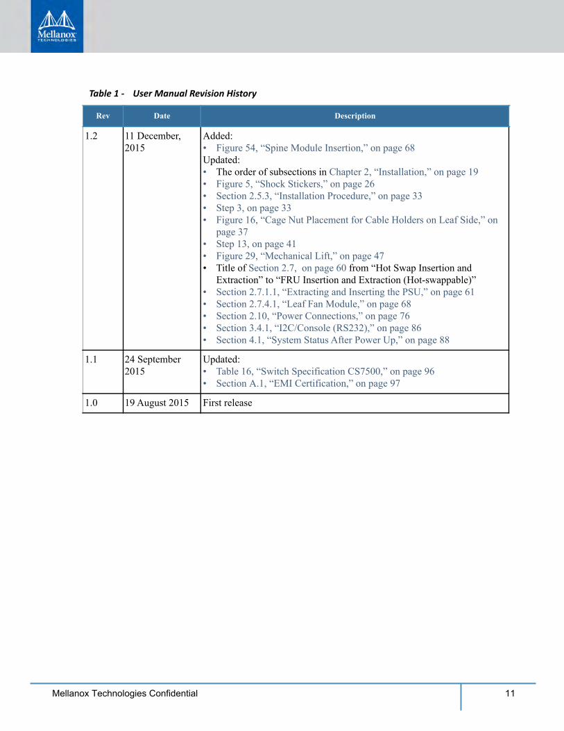
Revision History Table 1 - User Manual Revision History
Rev Date Description
2.3 14 October, 2017 Updated:“Air Cleanliness” note to Chapter 2, “Installation”
2.2 14 August, 2017 Updated:Note to Chapter 2.7.2, “Leaf Modules”Note to Chapter 2.7.3, “Spine Modules”
2.1 5 March, 2017 Added:Appendix F, “MNG Console Interfaces,” on page 106Note to Appendix 3.4.1, “I2C/Console (RS232),” on page 86
2.0 8 February, 2017 Updated:Appendix H.14, “ ( ),” on page 144
1.9 1 December, 2016 Updated:• “Extracting Spine Module #1 or #2” on page 65
1.8 22 August, 2016 Updated:• Section 3.1.1, “Power Supply Unit LEDs,” on page 77
1.7 06 July, 2016 Updated “Total Power Consumption EDR” field in Table 16, “Switch Specification CS7500,” on page 96.
1.6 29 June, 2016 Added Section 1.5, “Fan Redundancy,” on page 18
1.5 1 May, 2016 Updated:• Document title• Section “About this Manual,” on page 12• Chapter 1, “Overview,” on page 14• Section 3.4.4, “Reset – RST,” on page 86• Appendix G, “Replacement Parts Ordering Numbers,” on page 107 with
Switch-IB 2 replacement leaf and spine
1.4 11 April, 2016 Added:• Section 2.5.2, “Required Installation Tools,” on page 32Updated:• Section 2.5.3, “Installation Procedure,” on page 33
1.3 20 March, 2016 Updated:• Note in Section 4.1, “System Status After Power Up,” on page 88• Section 6.1, “Power Supply Unit,” on page 92 step 7• “Regulatory Compliance” in Table 16, “Switch Specification CS7500,”
on page 96
11Mellanox Technologies Confidential
1.2 11 December, 2015
Added:• Figure 54, “Spine Module Insertion,” on page 68Updated:• The order of subsections in Chapter 2, “Installation,” on page 19• Figure 5, “Shock Stickers,” on page 26• Section 2.5.3, “Installation Procedure,” on page 33• Step 3, on page 33• Figure 16, “Cage Nut Placement for Cable Holders on Leaf Side,” on
page 37• Step 13, on page 41• Figure 29, “Mechanical Lift,” on page 47• Title of Section 2.7, on page 60 from “Hot Swap Insertion and
Extraction” to “FRU Insertion and Extraction (Hot-swappable)”• Section 2.7.1.1, “Extracting and Inserting the PSU,” on page 61• Section 2.7.4.1, “Leaf Fan Module,” on page 68• Section 2.10, “Power Connections,” on page 76• Section 3.4.1, “I2C/Console (RS232),” on page 86• Section 4.1, “System Status After Power Up,” on page 88
1.1 24 September 2015
Updated:• Table 16, “Switch Specification CS7500,” on page 96• Section A.1, “EMI Certification,” on page 97
1.0 19 August 2015 First release
Table 1 - User Manual Revision History
Rev Date Description
12 Mellanox Technologies Confidential
About this ManualThis manual provides an overview of the Switch-IB™/Switch-IB™ 2 series based InfiniBand CS7500 director switch and guidelines for its operation.
Intended AudienceThis manual is intended for users and system administrators responsible for installing and setting up the chassis platform.
The manual assumes familiarity with the InfiniBand® architecture specification.
Related DocumentationThe documentation set accompanying the QSFP28 Chassis InfiniBand Switch platform includes the following:Table 2 - Reference Documents and Websites
Document Name Description
InfiniBand Architecture Specifica-tion, Vol. 1, Release 1.2.1
The InfiniBand Architecture Specification that is pro-vided by IBTA
Switch Product Release Notes For possible hardware issues see the switch support prod-uct page. This requires a customer support login. Look up the relevant Switch-IB™ based switch system/series release note file.
MLNX-OS® User Manual for VPI This document contains information regarding configur-ing and managing Mellanox Technologies SwitchX® switch platforms listing all of the commands available through MLNX-OS with explanations and examples.
Dismantling Procedures Dismantling user guides for Mellanox Technologies prod-ucts organized by product category.http://www.mellanox.com/page/dismantling_procedures
ConventionsThroughout this manual, the name CS7500 and the terms chassis and switch are used to describe the port QSFP28 InfiniBand chassis, unless explicitly indicated otherwise.The following icons are used throughout this document to indicate information that is important to the user.
This symbol indicates information that is helpful to the user.
13Mellanox Technologies Confidential
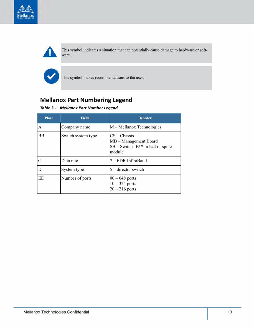
Mellanox Part Numbering LegendTable 3 - Mellanox Part Number Legend
Place Field Decoder
A Company name M – Mellanox Technologies
BB Switch system type CS – ChassisMB – Management BoardSB – Switch-IB™ in leaf or spine module
C Data rate 7 – EDR InfiniBand
D System type 5 – director switch
EE Number of ports 00 – 648 ports10 – 324 ports20 – 216 ports
This symbol indicates a situation that can potentially cause damage to hardware or soft-ware.
This symbol makes recommendations to the user.
14 Mellanox Technologies Confidential
1 OverviewThis chapter provides an overview of the CS7500 QSFP28 InfiniBand director switch platform (referenced in this document as “the chassis” or “the switch”) and its operational environment.The Mellanox CS7500 switch system provides the highest performing fabric solution by deliver-ing high bandwidth and low latency to enterprise data centers (EDC), high-performance comput-ing (HPC) and embedded environments. Networks built with the CS7500 system can carry converged traffic with the combination of assured bandwidth and granular quality of service. Built with Mellanox’s 6th and 7th generation of Switch-IB™ and Switch-IB™ 2 switch devices, CS7500 systems provide up to 100Gb/s full bidirectional bandwidth per port. With up to 648ports in a 28U rack space, this system is among the densest switching systems available.The switch platform comes pre-installed with all necessary firmware for standard operation within an InfiniBand fabric and requires an InfiniBand compliant Subnet Manager running from one of the hosts or the management module of the switch system. The initial configuration proce-dure should be followed to initialize the switch before connecting it to the network after which normal operation can proceed. (See the installation guide for details regarding the initial configu-ration.) Once connected to the network, the Subnet Management software automatically discov-ers and configures the fabric and begins utilizing the switch.The Mellanox Operating System (MLNX-OS®) software package provides a subnet manager and network management tools as well as connectivity software for servers and storage, and is available on the Mellanox website.Basic installation is covered in Chapter 2, “Installation” on page 1.
Hot-swapping components and hardware maintenance is covered in Section 2.7, “FRU Insertion and Extraction (Hot-Swappable),” on page 38.
1.1 Product Information
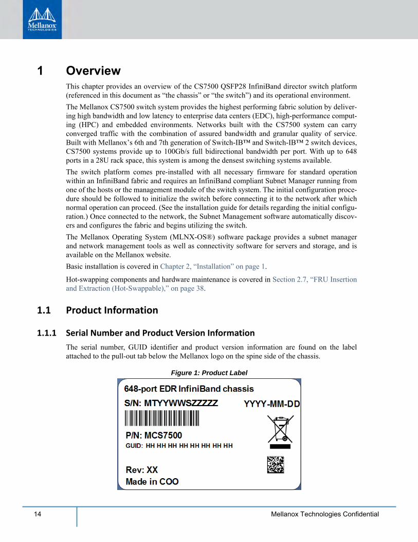
1.1.1 Serial Number and Product Version InformationThe serial number, GUID identifier and product version information are found on the label attached to the pull-out tab below the Mellanox logo on the spine side of the chassis.
Figure 1: Product Label
Overview
15Mellanox Technologies Confidential
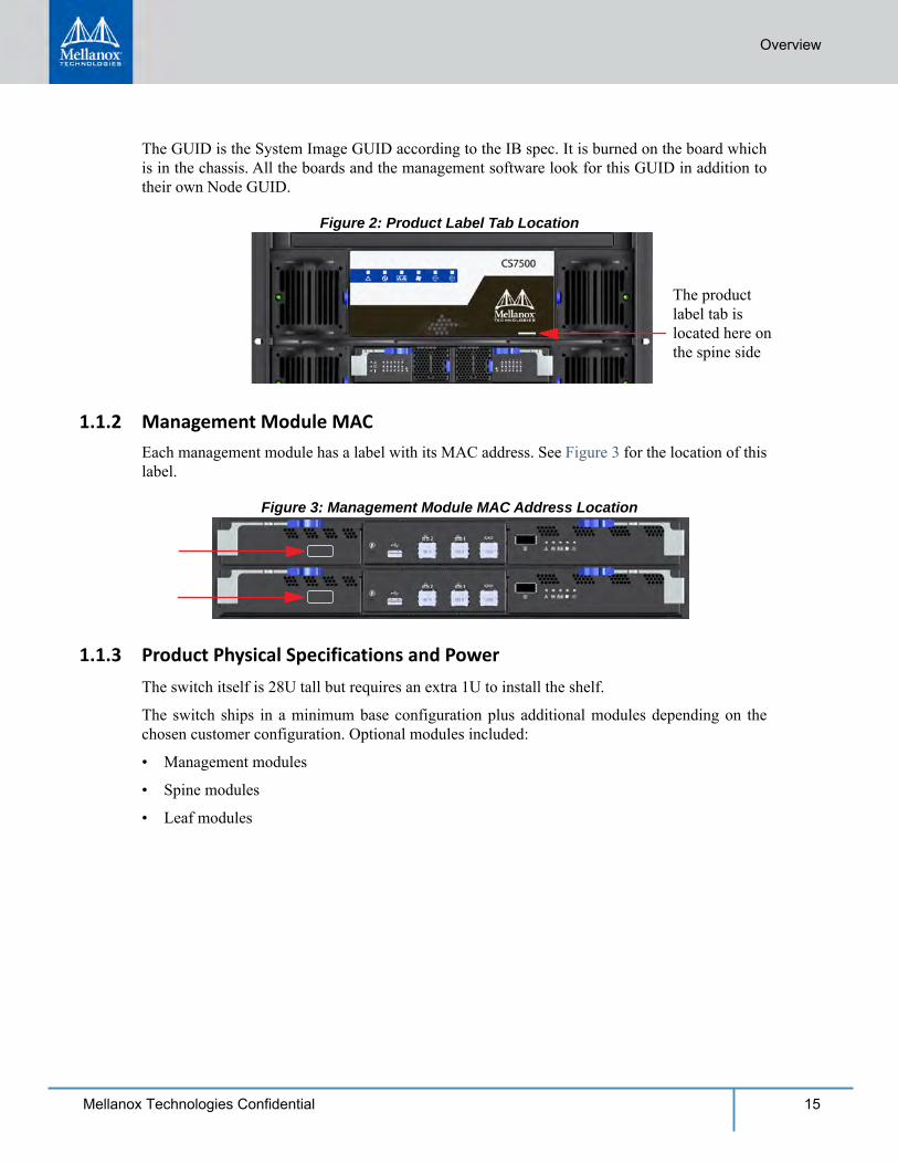
The GUID is the System Image GUID according to the IB spec. It is burned on the board which is in the chassis. All the boards and the management software look for this GUID in addition to their own Node GUID.
Figure 2: Product Label Tab Location
The product label tab is located here on the spine side
1.1.2 Management Module MACEach management module has a label with its MAC address. See Figure 3 for the location of this label.
Figure 3: Management Module MAC Address Location
1.1.3 Product Physical Specifications and PowerThe switch itself is 28U tall but requires an extra 1U to install the shelf.
The switch ships in a minimum base configuration plus additional modules depending on the chosen customer configuration. Optional modules included:
• Management modules
• Spine modules
• Leaf modules

16 Mellanox Technologies Confidential
The following figure presents a fully populated leaf and spine side.
Figure 4: CS7500
Leafs Each leaf has 36 ports and up to 18
leafs can fit in the chassis
Chassis fan modules
Power supply units: 10
Spines
AC inlets
Fuse box (Do not tamper with)
Power supplies
Management modules: 2
Spine modules: 18
Leaf modules: 18
Chassis fan modules: 20
AC inlets: 10
Management Modules
Overview
17Mellanox Technologies Confidential
1.2 Features List• 648 EDR (100Gb/s) InfiniBand ports in a 28U switch
• 130 Tb/s aggregate data switching capacity with ultra low latency
• IBTA 1.3 and 1.2.1 compliant
• Up to EDR link speeds
• N+N power supply
• Chassis high availability
• sMB high availability
1.3 InfiniBand EDR OverviewThe Mellanox CS7500 switch system supports EDR, standard InfiniBand data rate, where each lane of a 4X port runs a bit rate of 25.78125Gb/s. The EDR physical layer is an IBTA specified physical layer using different block types, deskew mechanism and framing rules.Both FDR and EDR support Forward Error Correction (FEC), as described in IEEE Std 802.3ap-2007 (Amendment to IEEE Std 802.3-2005) chapter 74.
1.4 Power Supply RedundancyThe CS7500 platform comes standard with 10 power supplies. Each power supply is capable to provide 48VDC 2500W output power.
1.4.1 AC Source RequirementsCS7500 system supports 220VAC operation only. No support for 110VAC source. Each AC source should be capable of providing at least 12A input current.
1.4.2 Power RedundancyThe minimum complement of PSUs which allows the chassis to run at full capacity is 5. The fol-lowing two redundancy options are available:• No redundancy (combined mode)
• N+N configuration (grid-redundant mode)
EDR is only guaranteed to work with approved Mellanox cables.
N+N redundancy only works with a supply voltage of 220V.
18 Mellanox Technologies Confidential
The chassis PSUs are fed from two power grids for high availability. The second power grid can be supplied by any of the following:• a backup power supply grid
• a generator
• a battery backup system
• any combination of the above
Connecting 5 power supplies to one power supply grid and the remaining 5 power supplies to a secondary power supply grid will create N+N redundancy. This is high availability. Under these conditions should a power grid fail (an electric company power failure or blackout for example) power grid High Availability will continue to keep the chassis running at full capacity through the secondary or backup power supply grid.
When the power drops below the required minimum due to power supply failure, MLNX-OS® may power down some leafs. If this happens it may be necessary to reboot the chassis once the defective PSU has been replaced. Two ways to reboot are to use the reboot command in the CLI or reboot through the WebUI.
Table 4 - Power Supply OPN
PSU OPN Wattage Description
MTDF-PS-A 2500W Supplies N+N redundancy for all switch chassis at 220 Volts
1.5 Fan RedundancyWhether it is a chassis, or a spine fan unit, Mellanox’s EDR director switch chassis supports sin-gle fan failure without performance degradation.When a fan unit fails, it must remain in the chassis until a replacement is available. At that point, the failed fan unit must be promptly replaced so that the chassis remains with an empty slot for as little time as possible.
The system cannot run with less than 5 PSUs, thus if one of the power grids is down there is no power or PSU redundancy in the system.
Installation
19Mellanox Technologies Confidential
2 Installation
Installation and initialization of the chassis is a simple process requiring attention to the normal mechanical, power, and thermal precautions for rack-mounted equipment. The chassis comes only with the power supplies and fans pre-installed. The rest of the openings are populated with blanks. All of the leafs, spines, and management modules are shipped in a separate package.The chassis requires initial configuration to get the chassis and fabric management up and run-ning through remote management.
2.1 Installation Safety WarningsThese safety warnings are in English. For other languages, please refer to the appendixes.1. Installation Instructions
2. Bodily Injury Due to Weight
This chassis can be installed in standard 19” racks that have depths between 715-850mm between the vertical supports of the rack.
This unit is intended for installation in a restricted access location. A restricted access area can be accessed only through the use of a special tool, lock and key, or other means of security.
Unless otherwise specified, Mellanox products are designed to work in an environ-mentally controlled data center with low levels of gaseous and dust (particulate) con-tamination.The operation environment should meet severity level G1 as per ISA 71.04 for gaseouscontamination and ISO 14644-1 class 8 for cleanliness level
Read all installation instructions before connecting the equipment to the power source.
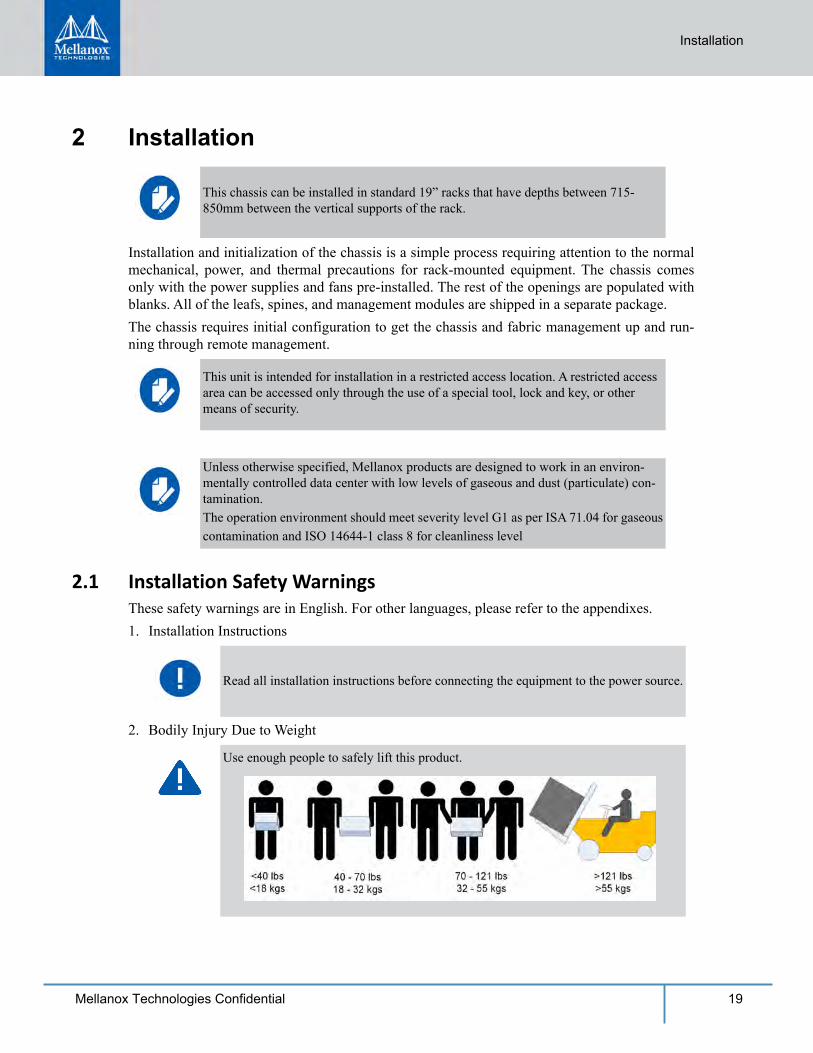
Use enough people to safely lift this product.
20 Mellanox Technologies Confidential
3. Heavy Equipment
4. Installation in Restricted Access Location
5. Risk of Electric Shock
6. Over-temperature
7. Stacking the Chassis
8. Redundant Power Supply Connection – Electrical Hazard
9. Double Pole/Neutral Fusing
10.Multiple Power Inlets
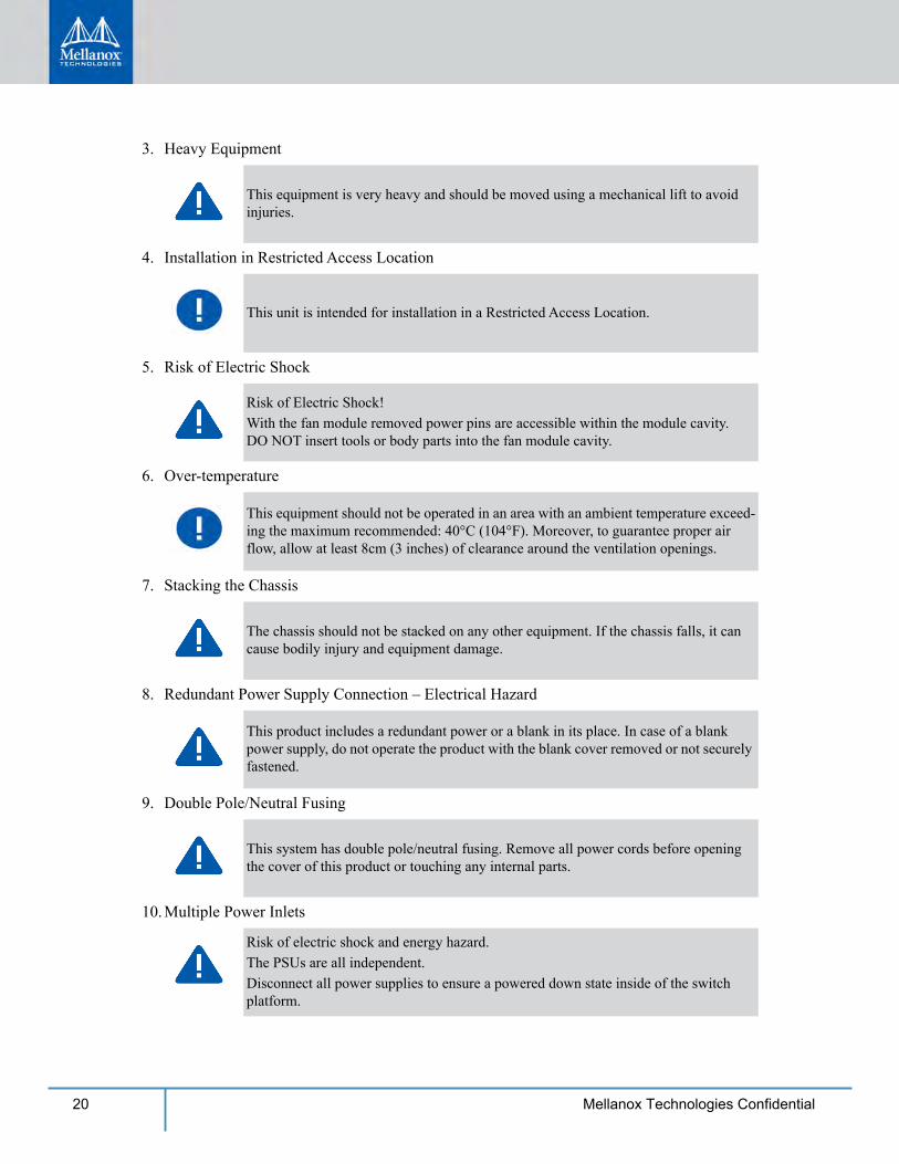
This equipment is very heavy and should be moved using a mechanical lift to avoid injuries.
This unit is intended for installation in a Restricted Access Location.
Risk of Electric Shock!With the fan module removed power pins are accessible within the module cavity. DO NOT insert tools or body parts into the fan module cavity.
This equipment should not be operated in an area with an ambient temperature exceed-ing the maximum recommended: 40°C (104°F). Moreover, to guarantee proper air flow, allow at least 8cm (3 inches) of clearance around the ventilation openings.
The chassis should not be stacked on any other equipment. If the chassis falls, it can cause bodily injury and equipment damage.
This product includes a redundant power or a blank in its place. In case of a blank power supply, do not operate the product with the blank cover removed or not securely fastened.
This system has double pole/neutral fusing. Remove all power cords before opening the cover of this product or touching any internal parts.
Risk of electric shock and energy hazard.The PSUs are all independent.Disconnect all power supplies to ensure a powered down state inside of the switch platform.
Installation
21Mellanox Technologies Confidential
11. During Lightning – Electrical Hazard
12.Copper InfiniBand Cable Connecting/Disconnecting
13.Rack Mounting and Servicing
14.Equipment Installation
15.Equipment Disposal
16.Local and National Electrical Codes
17. Installation Codes
18.Battery Replacement
During periods of lightning activity, do not work on the equipment or connect or dis-connect cables.
Copper InfiniBand cables are heavy and not flexible, as such they should be carefully attached to or detached from the connectors. Refer to the cable manufacturer for spe-cial warnings/instructions.
When this product is mounted or serviced in a rack, special precautions must be taken to ensure that the system remains stable. In general you should fill the rack with equip-ment starting from the bottom to the top.
This equipment should be installed, replaced, and/or serviced only by trained and qual-ified personnel.
Disposal of this equipment should be in accordance to all national laws and regula-tions.
This equipment should be installed in compliance with local and national electrical codes.
This device must be installed according to the latest version of the country national electrical codes. For North America, equipment must be installed in accordance to the applicable requirements in the US National Electrical Code and the Canadian Electri-cal Code.
Warning: Replace only with UL Recognized battery, certified for maximum abnormal charging current not less than 4mAThere is a risk of explosion should the battery be replaced with a battery of an incorrect type.Dispose of used batteries according to the instructions.
22 Mellanox Technologies Confidential
19.UL Listed and CSA Certified Power Supply Cord
20.High Leakage Current
21.Add GND connection information
22. Installation Codes
23. Interconnection of Units
24.Hazardous Radiation Exposure
For North American power connection, select a power supply cord that is UL Listed and CSA Certified, 3 - conductor, [16 AWG], terminated with a molded plug rated at 125 V, [13 A], with a minimum length of 1.5m [six feet] but no longer than 4.5m.For European connection, select a power supply cord that is internationally harmonized and marked “<HAR>”, 3 - conductor, minimum 1.0 mm2 wire, rated at 300 V, with a PVC insulated jacket. The cord must have a molded plug rated at 250 V, 10 A.
Warning: High leakage current; Earth connection essential before connecting supply.
Before connecting this device to the power line, the protective earth terminal screws of this device must be connected to the protective earth in the building installation.(GND Connection Information): The building installation shall provide a means for a connection to protective earth; and the equipment shall be permanently connected to that by a service person. A SERVICE PERSON shall check whether or not the socket - outlet from which the equipment is to be powered provides a connection to the building protective earth. If not, the SERVICE PERSON shall arrange for the installation of a PROTECTIVEEARTHING CONDUCTOR from the separate protective earthing terminal to the pro-tective earth wire in the building. The equipment shall be installed in area where equi-potential bonding exists ((such as a telecommunication centre or a dedicated computer room).
This device must be installed according to the latest version of the country national electrical codes. For North America, equipment must be installed in accordance to the applicable requirements in the US National Electrical Code and the Canadian Electri-cal Code.
Cables for connecting to the unit RS232 and Ethernet Interfaces must be UL certified type DP-1 or DP-2. (Note- when residing in non LPS circuit) Overcurrent Protection: A readily accessible Listed branch circuit overcurrent protec-tive device rated 20 A must be incorporated in the building wiring.
Caution – Use of controls or adjustment or performance of procedures other than those specified herein may result in hazardous radiation exposure.
Installation
23Mellanox Technologies Confidential
25.Proper Enclosure
26.Do Not Use the Switch as a Shelf or Work Space
27.WEEE Directive
28.Country of Norway Power Restrictions
2.2 Environmental and Safety RecommendationsThe following are Mellanox recommendations.
CLASS 1 LASER PRODUCT and reference to the most recent laser standards IEC 60 825-1:1993 + A1:1997 + A2:2001 and EN 60825-1:1994+A1:1996+ A2:2001
A suitable electrical, mechanical and fire enclosure shall be provided by the end prod-uct manufacturer and or the end user.
Caution: Slide/rail mounted equipment is not to be used as a shelf or a work space. The rails are not intended for sliding the unit away from the rack. It is for permanent instal-lation at final resting place only, not used for service and maintenance
According to the WEEE Directive 2002/96/EC, all waste electrical and electronic equipment (EEE) should be collected separately and not disposed of with regular household waste.Dispose of this product and all of its parts in a responsible and environmentally friendly way.
This unit is intended for connection to a TN power system and an IT power system of Norway only.
Recommended ambient temperature in the System room is 20±5oC.Recommended humidity range is 40%±15% without condensing.
It is highly recommended that the installation sites be as isolated as possible from all sources of radio transmissions and electrical interference.
24 Mellanox Technologies Confidential
2.3 Switch ComponentsThe system’s components are shipped as specified below.
Chassis Crate
The switch system chassis is shipped in a dedicated crate which includes the following boxes:1. Switch system chassis with the leaf fan and power supply modules already installed.2. Chassis installation kit (see Table 5, “Chassis Installation Kit Items,” on page 29)3. Cable holders (see Table 6, “Cable Management Installation Kit Parts,” on page 31)4. One box containing 6 smaller boxes with cable shelves5. 1 box containing 104 power cords (250V 16A 2m, C19 to C20, USA UL Standard)The management, spine, and leaf modules are shipped separately.
It is highly recommended that the installation site building be equipped with a light-ning rod.
It is highly recommended that the installation site be equipped with smoke detectors and a fire alarm warning system.
The system requires a KVA rated UPS system. It is recommended that a UPS system be installed to protect the equipment in the event of unexpected power failure.
Make sure that the outlets and circuits will not be overloaded. Spread out the load over at least two or three circuits or use a 3 phase circuit.
To completely populate the CS7500 chassis, one requires 2 management module boxes, 18 spine module boxes, and 18 leaf module boxes.
Installation
25Mellanox Technologies Confidential
Spine Module Boxes
Each box contains 1 spine module with its fan modules already installed.
Leaf Module Boxes
Each box contains 1 leaf module.Management Module BoxesEach box contains 1 management module and 1 RJ45-to-DB9 cable.
2.4 Unpacking the Switch System
2.4.1 Verifying Crate ConditionThe crate has a shock sticker applied. When receiving the crate, look for and inspect the shock sticker to confirm that it has not triggered.
The shock stickers turn red if the crate has been mishandled or handled roughly. If one of the shock stickers is red, notify the shipper and Mellanox.
This unit is intended for installation in a restricted access location. A restricted access area can be accessed only through the use of a special tool, lock and key, or other means of security.
IMPORTANT NOTEThe shock sticker does not necessarily indicate damage to the contents. However, be sure to carefully inspect the contents of a crate with a triggered sticker.
26 Mellanox Technologies Confidential
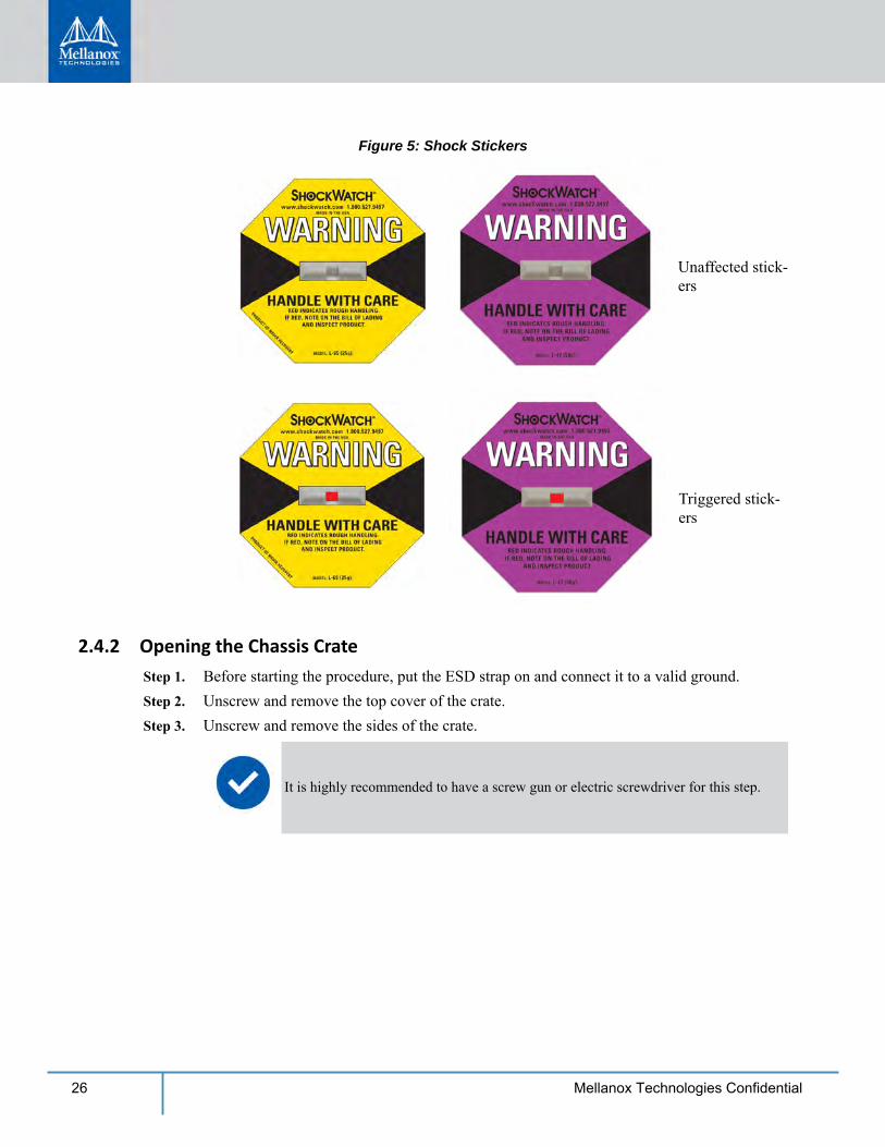
Figure 5: Shock Stickers
Unaffected stick-ers
Triggered stick-ers
2.4.2 Opening the Chassis Crate Step 1. Before starting the procedure, put the ESD strap on and connect it to a valid ground. Step 2. Unscrew and remove the top cover of the crate. Step 3. Unscrew and remove the sides of the crate.
It is highly recommended to have a screw gun or electric screwdriver for this step.
Installation
27Mellanox Technologies Confidential
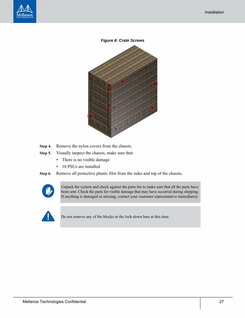
Figure 6: Crate Screws
Step 4. Remove the nylon covers from the chassis. Step 5. Visually inspect the chassis, make sure that:
• There is no visible damage• 10 PSUs are installed
Step 6. Remove all protective plastic film from the sides and top of the chassis.
Unpack the system and check against the parts list to make sure that all the parts have been sent. Check the parts for visible damage that may have occurred during shipping. If anything is damaged or missing, contact your customer representative immediately.
Do not remove any of the blocks or the lock-down bars at this time.
28 Mellanox Technologies Confidential
2.5 Physical Installation
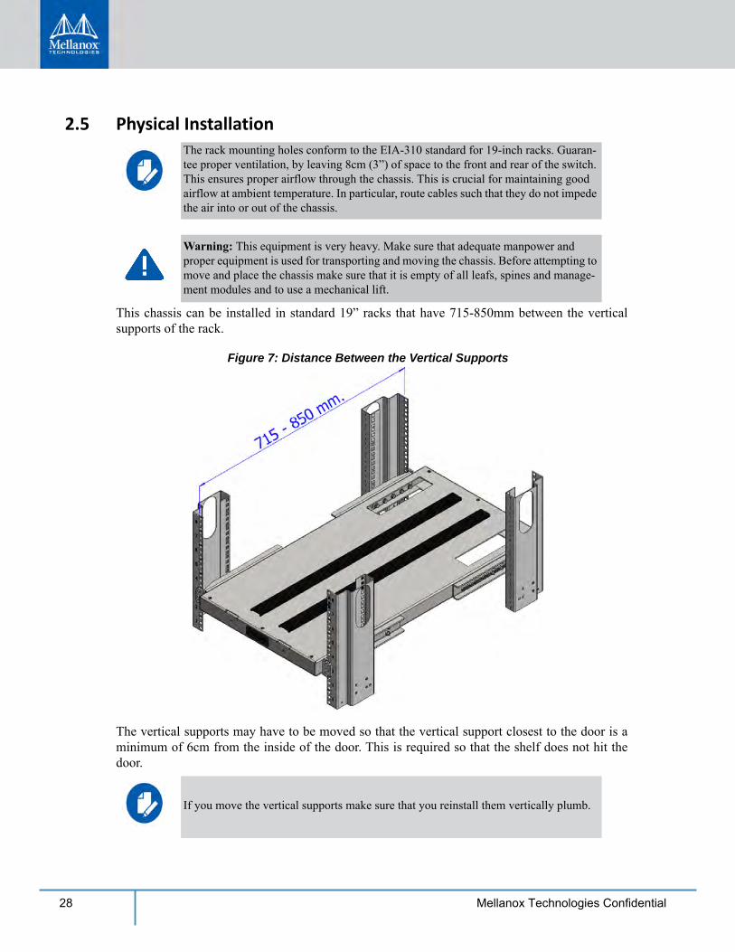
This chassis can be installed in standard 19” racks that have 715-850mm between the vertical supports of the rack.
Figure 7: Distance Between the Vertical Supports
The vertical supports may have to be moved so that the vertical support closest to the door is a minimum of 6cm from the inside of the door. This is required so that the shelf does not hit the door.
The rack mounting holes conform to the EIA-310 standard for 19-inch racks. Guaran-tee proper ventilation, by leaving 8cm (3”) of space to the front and rear of the switch. This ensures proper airflow through the chassis. This is crucial for maintaining good airflow at ambient temperature. In particular, route cables such that they do not impede the air into or out of the chassis.
Warning: This equipment is very heavy. Make sure that adequate manpower and proper equipment is used for transporting and moving the chassis. Before attempting to move and place the chassis make sure that it is empty of all leafs, spines and manage-ment modules and to use a mechanical lift.
If you move the vertical supports make sure that you reinstall them vertically plumb.
Installation
29Mellanox Technologies Confidential
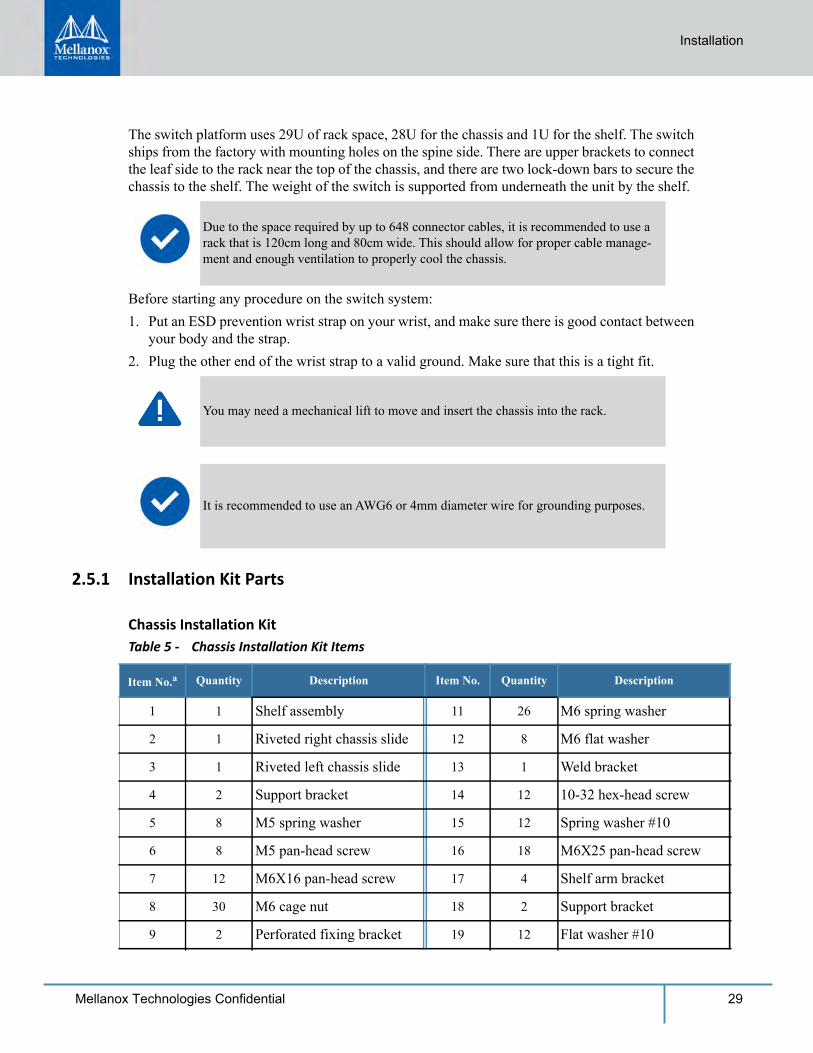
The switch platform uses 29U of rack space, 28U for the chassis and 1U for the shelf. The switch ships from the factory with mounting holes on the spine side. There are upper brackets to connect the leaf side to the rack near the top of the chassis, and there are two lock-down bars to secure the chassis to the shelf. The weight of the switch is supported from underneath the unit by the shelf.
Before starting any procedure on the switch system:1. Put an ESD prevention wrist strap on your wrist, and make sure there is good contact between
your body and the strap.2. Plug the other end of the wrist strap to a valid ground. Make sure that this is a tight fit.
2.5.1 Installation Kit Parts
Chassis Installation Kit
Due to the space required by up to 648 connector cables, it is recommended to use a rack that is 120cm long and 80cm wide. This should allow for proper cable manage-ment and enough ventilation to properly cool the chassis.
You may need a mechanical lift to move and insert the chassis into the rack.
It is recommended to use an AWG6 or 4mm diameter wire for grounding purposes.
Table 5 - Chassis Installation Kit Items
Item No.a Quantity Description Item No. Quantity Description
1 1 Shelf assembly 11 26 M6 spring washer
2 1 Riveted right chassis slide 12 8 M6 flat washer
3 1 Riveted left chassis slide 13 1 Weld bracket
4 2 Support bracket 14 12 10-32 hex-head screw
5 8 M5 spring washer 15 12 Spring washer #10
6 8 M5 pan-head screw 16 18 M6X25 pan-head screw
7 12 M6X16 pan-head screw 17 4 Shelf arm bracket
8 30 M6 cage nut 18 2 Support bracket
9 2 Perforated fixing bracket 19 12 Flat washer #10
30 Mellanox Technologies Confidential
Figure 8: Chassis Installation Kit
10 8 M6X16 hex-head screw –– –– ––––––––––––
a. Use the item number to identify the corresponding item in Figure 8. Each item number appears in a call-out bubble.
Table 5 - Chassis Installation Kit Items
Item No.a Quantity Description Item No. Quantity Description
Installation
31Mellanox Technologies Confidential
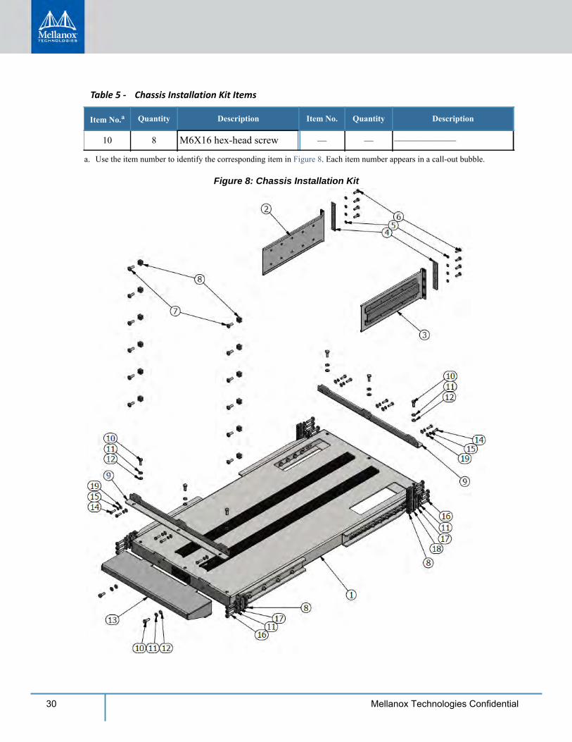
Cable Management Installation KitTable 6 - Cable Management Installation Kit Parts
Item No.a
a. Use the item number to identify the corresponding item in Figure 9. Each item number appears in a call-out bubble.
1 1 Left riveted cable holder 3 14 Pan-head screw
2 1 Right riveted cable holder 4 14 M6 cage nut
Figure 9: Cable Management Installation
Quantity Description Item No. Quantity Description
32 Mellanox Technologies Confidential
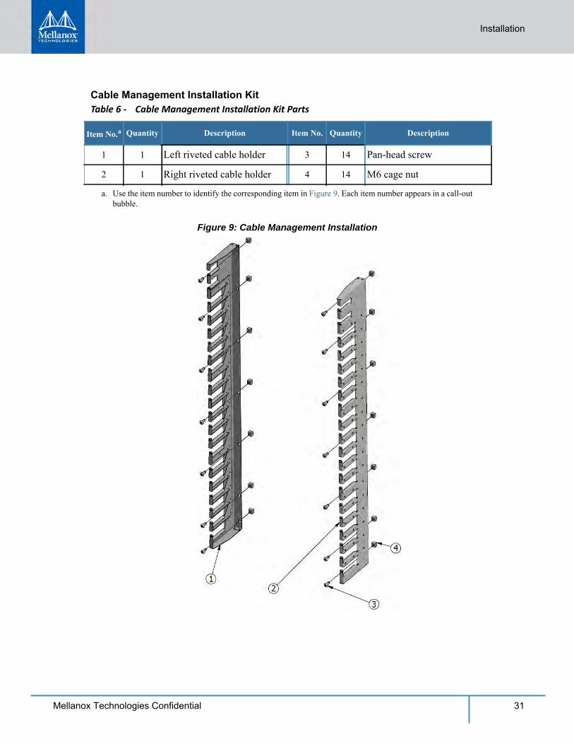
Shelf Installation KitThe shelf installation kit includes 18 shelves only.
Figure 10: Shelf Installation Kit
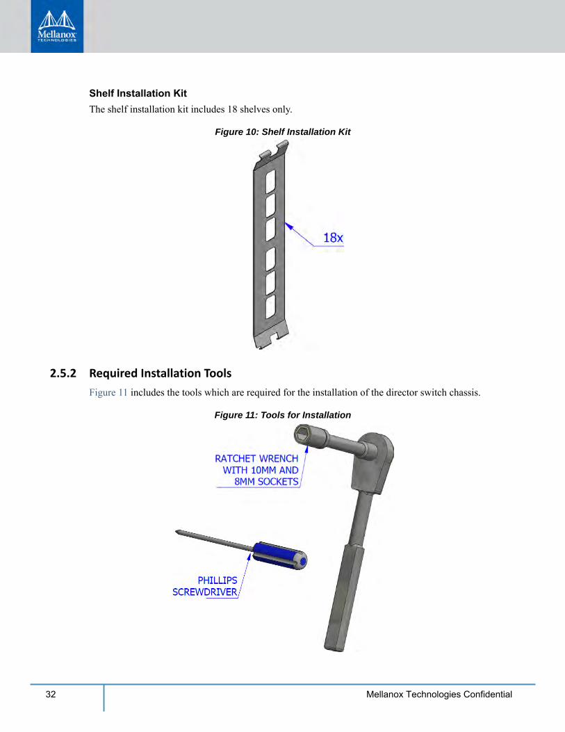
2.5.2 Required Installation ToolsFigure 11 includes the tools which are required for the installation of the director switch chassis.
Figure 11: Tools for Installation
Installation
33Mellanox Technologies Confidential
2.5.3 Installation Procedure
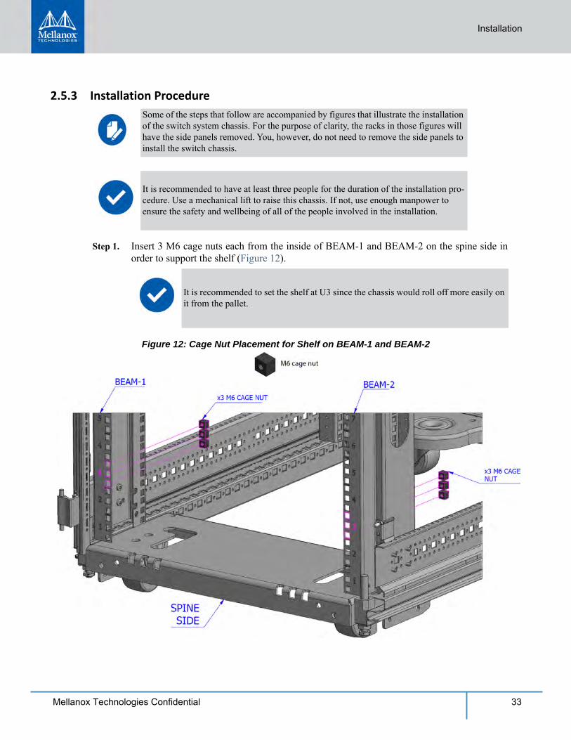
Step 1. Insert 3 M6 cage nuts each from the inside of BEAM-1 and BEAM-2 on the spine side in order to support the shelf (Figure 12).
Figure 12: Cage Nut Placement for Shelf on BEAM-1 and BEAM-2
Some of the steps that follow are accompanied by figures that illustrate the installation of the switch system chassis. For the purpose of clarity, the racks in those figures will have the side panels removed. You, however, do not need to remove the side panels to install the switch chassis.
It is recommended to have at least three people for the duration of the installation pro-cedure. Use a mechanical lift to raise this chassis. If not, use enough manpower to ensure the safety and wellbeing of all of the people involved in the installation.
It is recommended to set the shelf at U3 since the chassis would roll off more easily on it from the pallet.
34 Mellanox Technologies Confidential
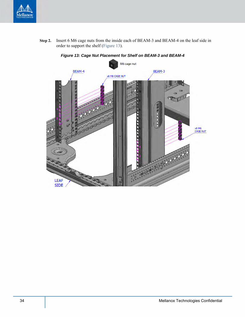
Step 2. Insert 6 M6 cage nuts from the inside each of BEAM-3 and BEAM-4 on the leaf side in order to support the shelf (Figure 13).
Figure 13: Cage Nut Placement for Shelf on BEAM-3 and BEAM-4
Installation
35Mellanox Technologies Confidential
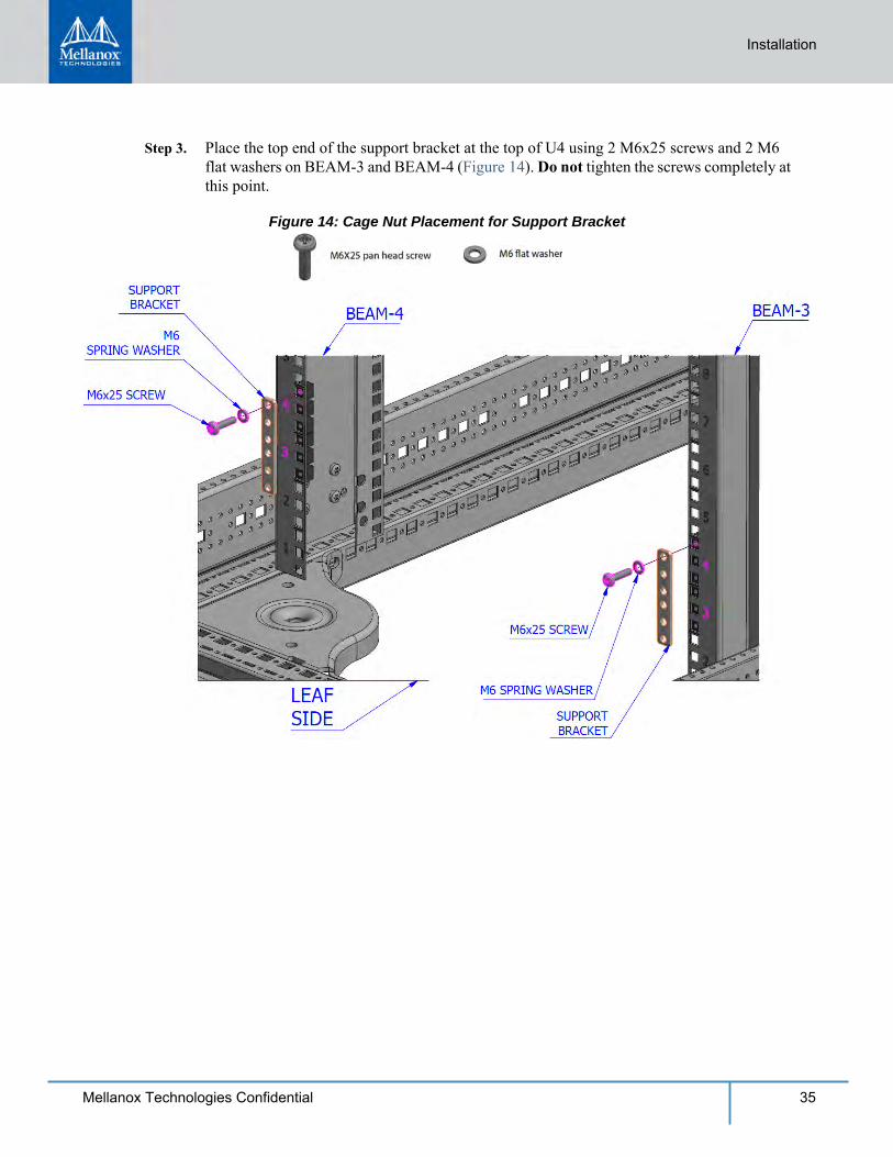
Step 3. Place the top end of the support bracket at the top of U4 using 2 M6x25 screws and 2 M6 flat washers on BEAM-3 and BEAM-4 (Figure 14). Do not tighten the screws completely at this point.
Figure 14: Cage Nut Placement for Support Bracket
36 Mellanox Technologies Confidential
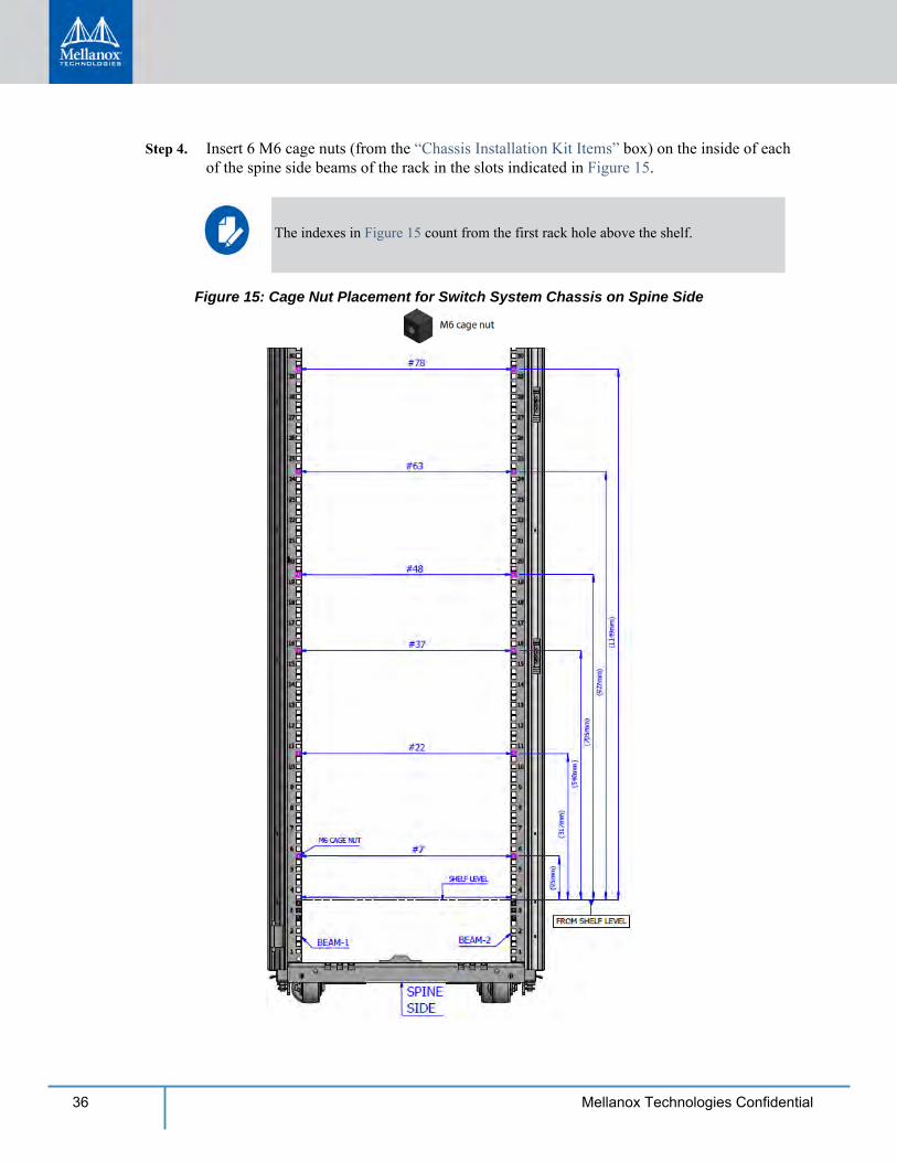
Step 4. Insert 6 M6 cage nuts (from the “Chassis Installation Kit Items” box) on the inside of each of the spine side beams of the rack in the slots indicated in Figure 15.
Figure 15: Cage Nut Placement for Switch System Chassis on Spine Side
The indexes in Figure 15 count from the first rack hole above the shelf.
Installation
37Mellanox Technologies Confidential
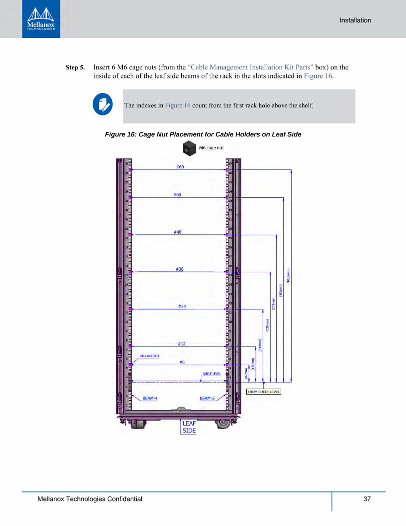
Step 5. Insert 6 M6 cage nuts (from the “Cable Management Installation Kit Parts” box) on the inside of each of the leaf side beams of the rack in the slots indicated in Figure 16.
Figure 16: Cage Nut Placement for Cable Holders on Leaf Side
The indexes in Figure 16 count from the first rack hole above the shelf.
38 Mellanox Technologies Confidential
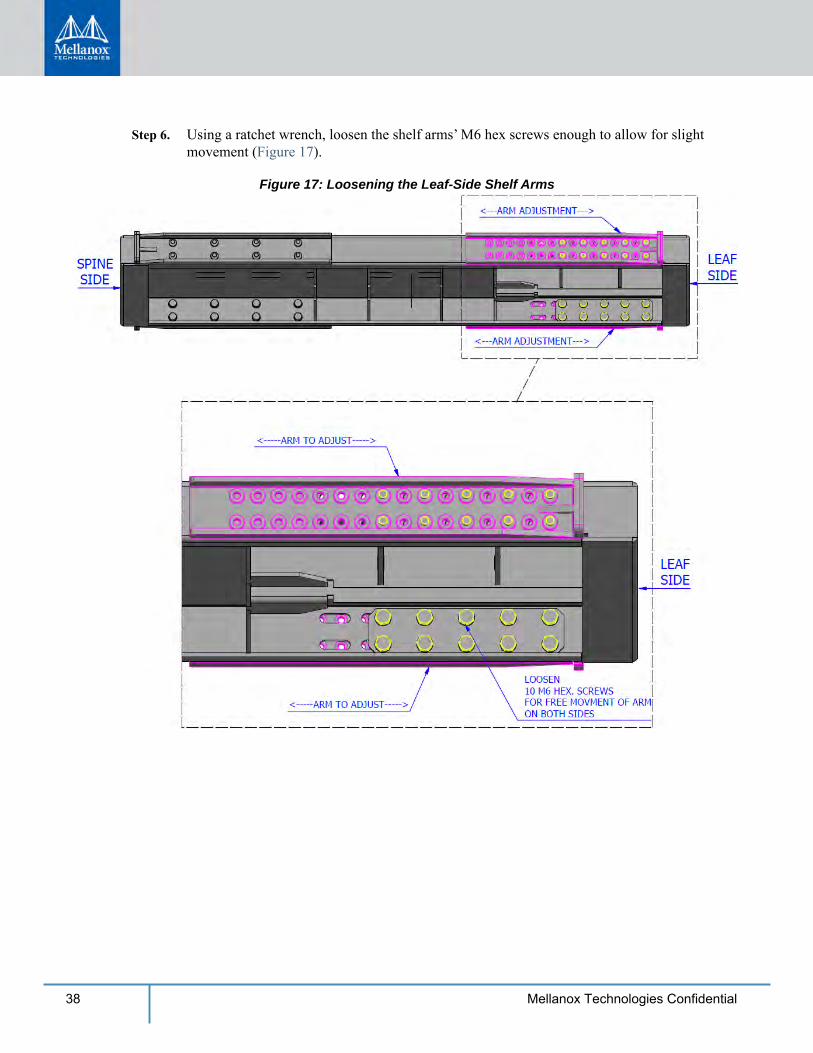
Step 6. Using a ratchet wrench, loosen the shelf arms’ M6 hex screws enough to allow for slight movement (Figure 17).
Figure 17: Loosening the Leaf-Side Shelf Arms
Installation
39Mellanox Technologies Confidential
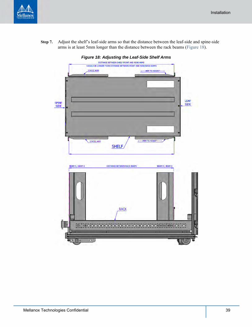
Step 7. Adjust the shelf’s leaf-side arms so that the distance between the leaf-side and spine-side arms is at least 5mm longer than the distance between the rack beams (Figure 18).
Figure 18: Adjusting the Leaf-Side Shelf Arms
40 Mellanox Technologies Confidential
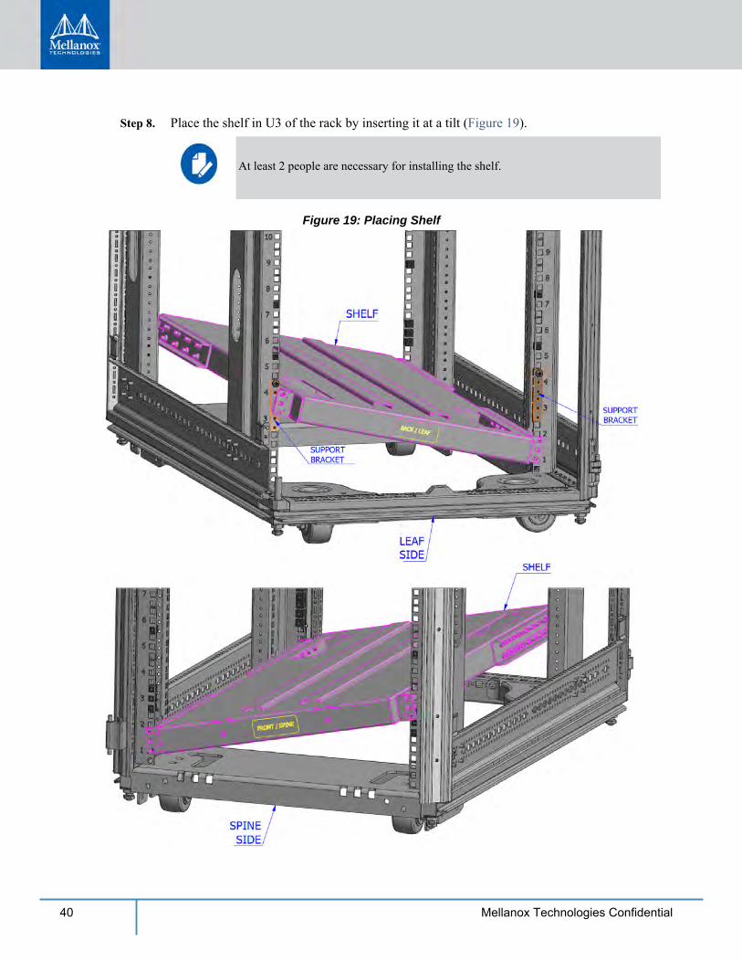
Step 8. Place the shelf in U3 of the rack by inserting it at a tilt (Figure 19).
Figure 19: Placing Shelf
At least 2 people are necessary for installing the shelf.
Installation
41Mellanox Technologies Confidential
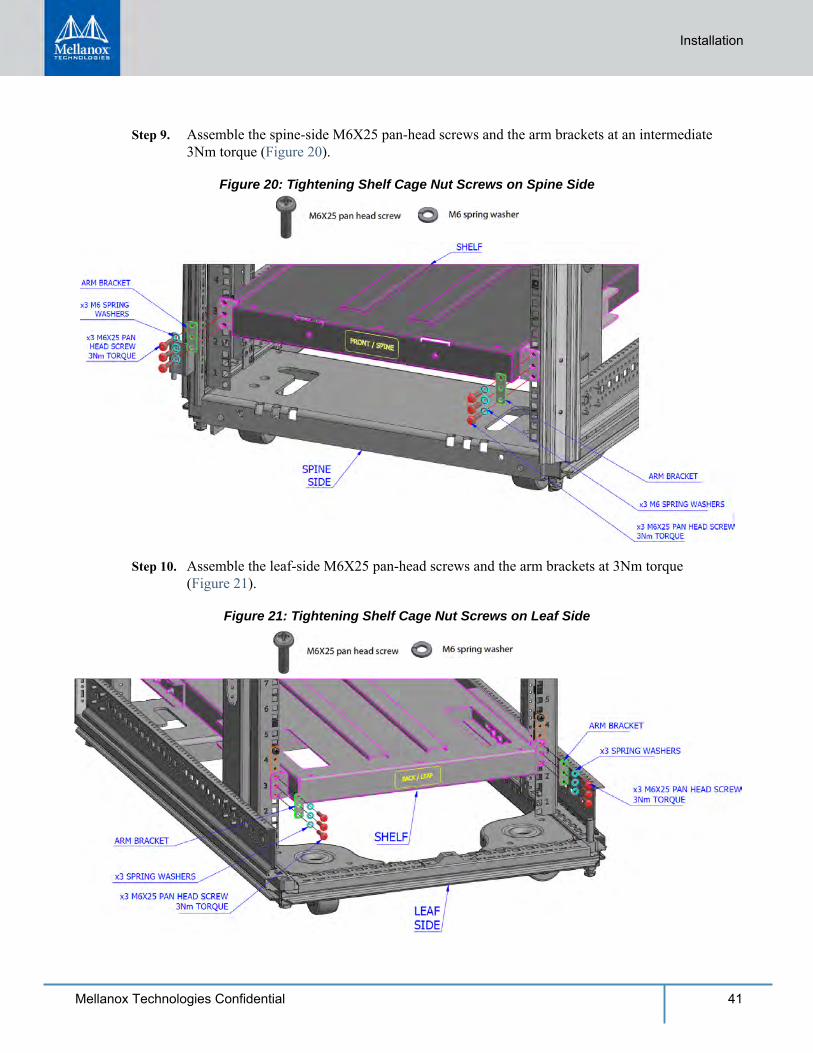
Step 9. Assemble the spine-side M6X25 pan-head screws and the arm brackets at an intermediate 3Nm torque (Figure 20).
Figure 20: Tightening Shelf Cage Nut Screws on Spine Side
Step 10. Assemble the leaf-side M6X25 pan-head screws and the arm brackets at 3Nm torque (Figure 21).
Figure 21: Tightening Shelf Cage Nut Screws on Leaf Side
42 Mellanox Technologies Confidential
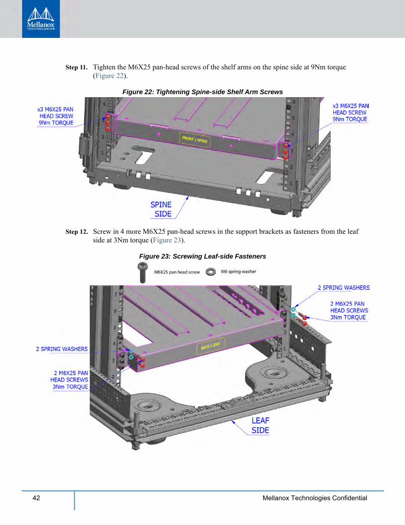
Step 11. Tighten the M6X25 pan-head screws of the shelf arms on the spine side at 9Nm torque (Figure 22).
Figure 22: Tightening Spine-side Shelf Arm Screws
Step 12. Screw in 4 more M6X25 pan-head screws in the support brackets as fasteners from the leaf side at 3Nm torque (Figure 23).
Figure 23: Screwing Leaf-side Fasteners
Installation
43Mellanox Technologies Confidential
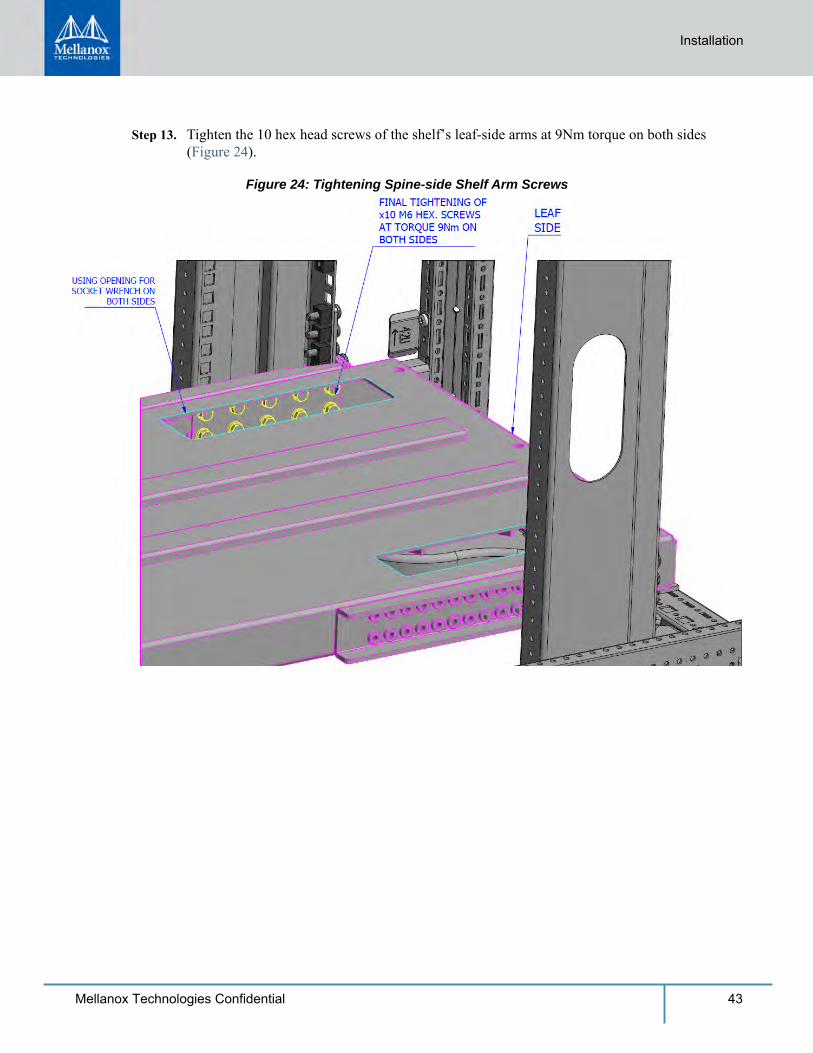
Step 13. Tighten the 10 hex head screws of the shelf’s leaf-side arms at 9Nm torque on both sides (Figure 24).
Figure 24: Tightening Spine-side Shelf Arm Screws
44 Mellanox Technologies Confidential
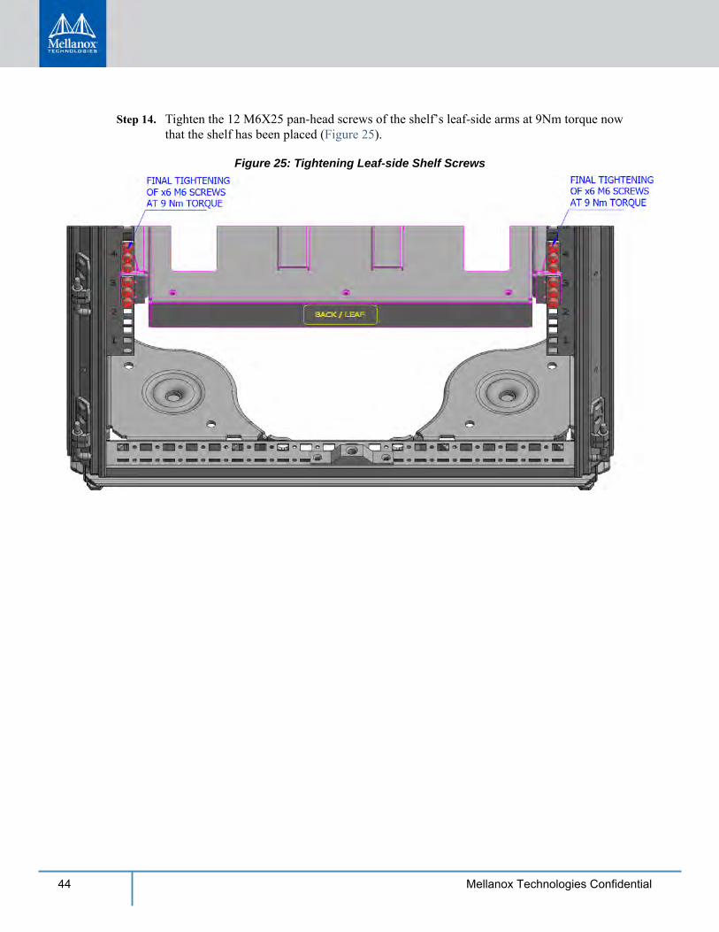
Step 14. Tighten the 12 M6X25 pan-head screws of the shelf’s leaf-side arms at 9Nm torque now that the shelf has been placed (Figure 25).
Figure 25: Tightening Leaf-side Shelf Screws
Installation
45Mellanox Technologies Confidential
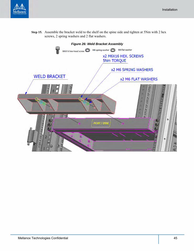
Step 15. Assemble the bracket weld to the shelf on the spine side and tighten at 5Nm with 2 hex screws, 2 spring washers and 2 flat washers.
Figure 26: Weld Bracket Assembly
46 Mellanox Technologies Confidential
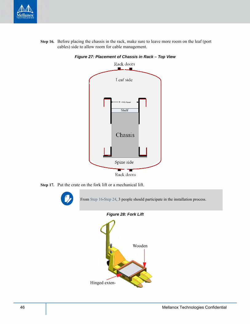
Step 16. Before placing the chassis in the rack, make sure to leave more room on the leaf (port cables) side to allow room for cable management.
Figure 27: Placement of Chassis in Rack – Top View
Step 17. Put the crate on the fork lift or a mechanical lift.
Figure 28: Fork Lift
Wooden
Hinged exten-
From Step 16-Step 24, 3 people should participate in the installation process.
Installation
47Mellanox Technologies Confidential
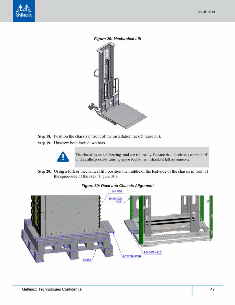
Figure 29: Mechanical Lift
Step 18. Position the chassis in front of the installation rack (Figure 30). Step 19. Unscrew both lock-down bars.
Step 20. Using a fork or mechanical lift, position the middle of the leaf-side of the chassis in front of the spine-side of the rack (Figure 30).
Figure 30: Rack and Chassis Alignment
The chassis is on ball bearings and can roll easily. Beware that the chassis can roll off of the pallet possibly causing grave bodily harm should it fall on someone.
48 Mellanox Technologies Confidential
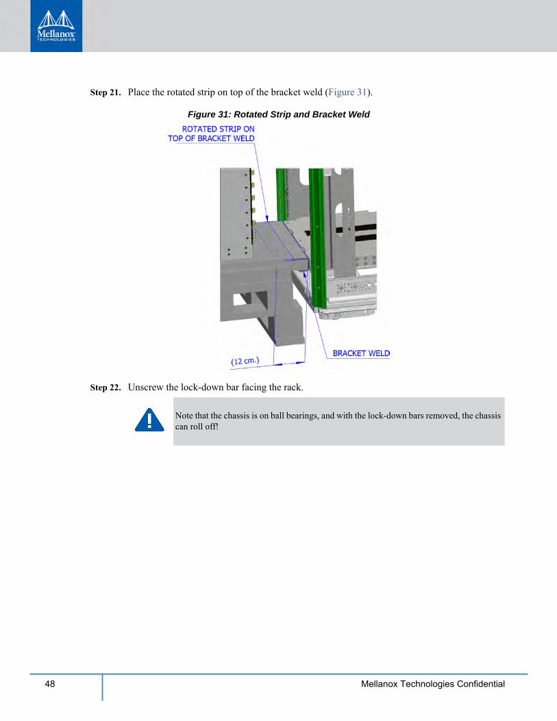
Step 21. Place the rotated strip on top of the bracket weld (Figure 31).
Figure 31: Rotated Strip and Bracket Weld
Step 22. Unscrew the lock-down bar facing the rack.
Note that the chassis is on ball bearings, and with the lock-down bars removed, the chassis can roll off!
Installation
49Mellanox Technologies Confidential
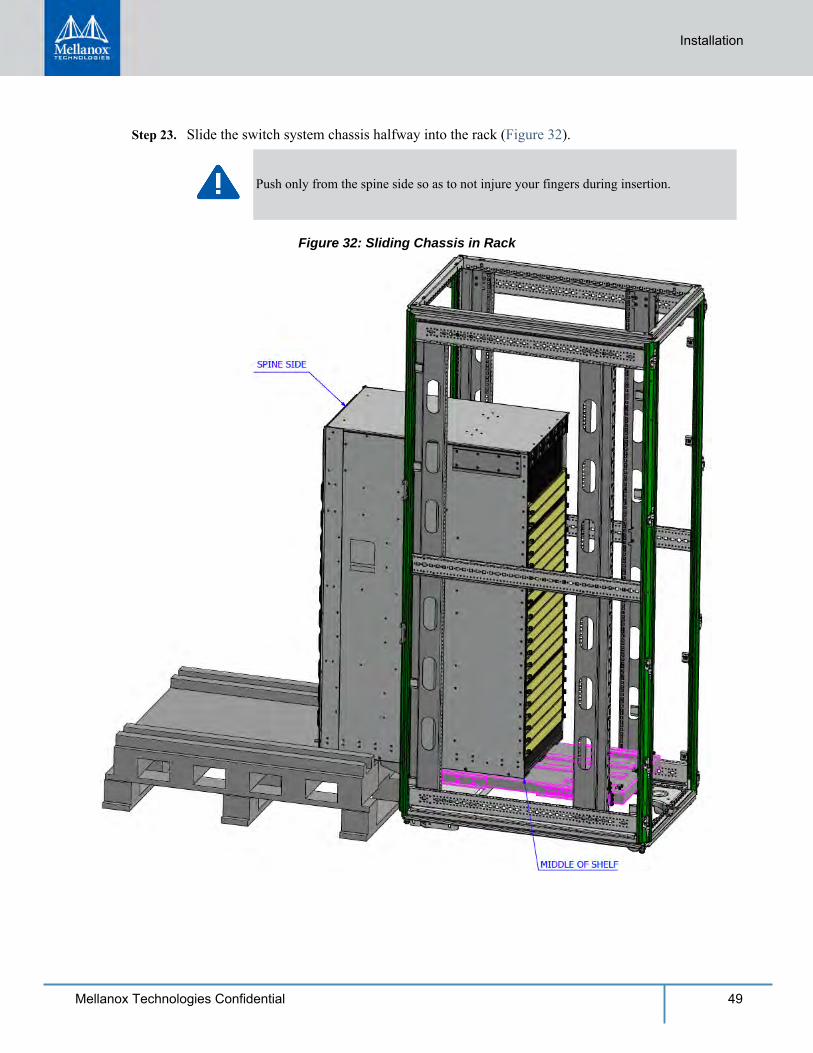
Step 23. Slide the switch system chassis halfway into the rack (Figure 32).
Figure 32: Sliding Chassis in Rack
Push only from the spine side so as to not injure your fingers during insertion.
50 Mellanox Technologies Confidential
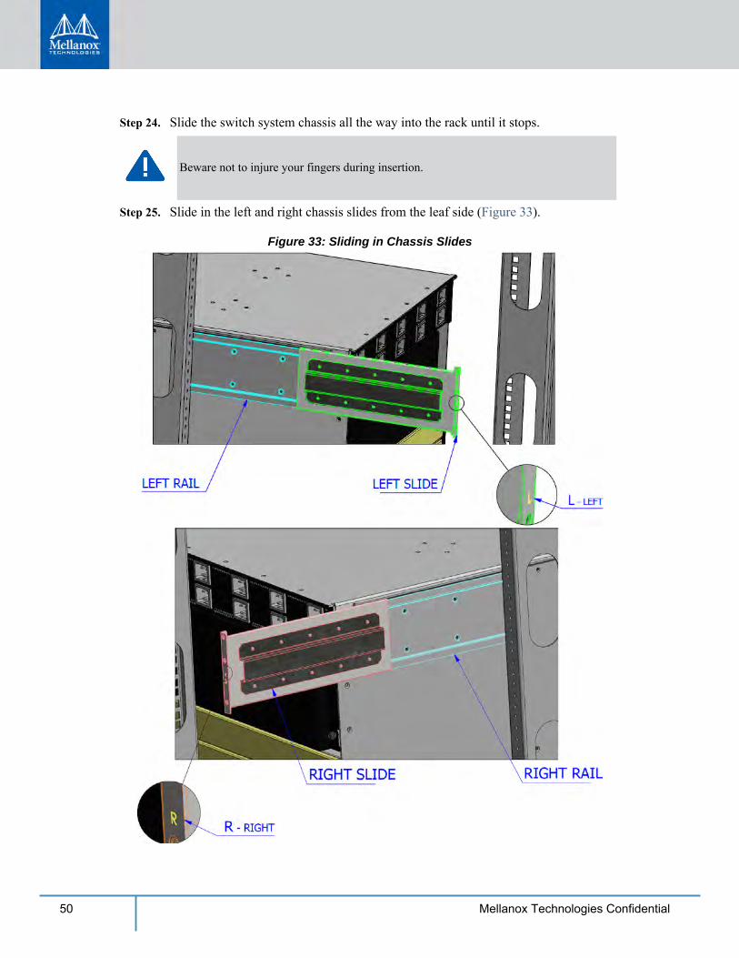
Step 24. Slide the switch system chassis all the way into the rack until it stops.
Step 25. Slide in the left and right chassis slides from the leaf side (Figure 33).
Figure 33: Sliding in Chassis Slides
Beware not to injure your fingers during insertion.
Installation
51Mellanox Technologies Confidential
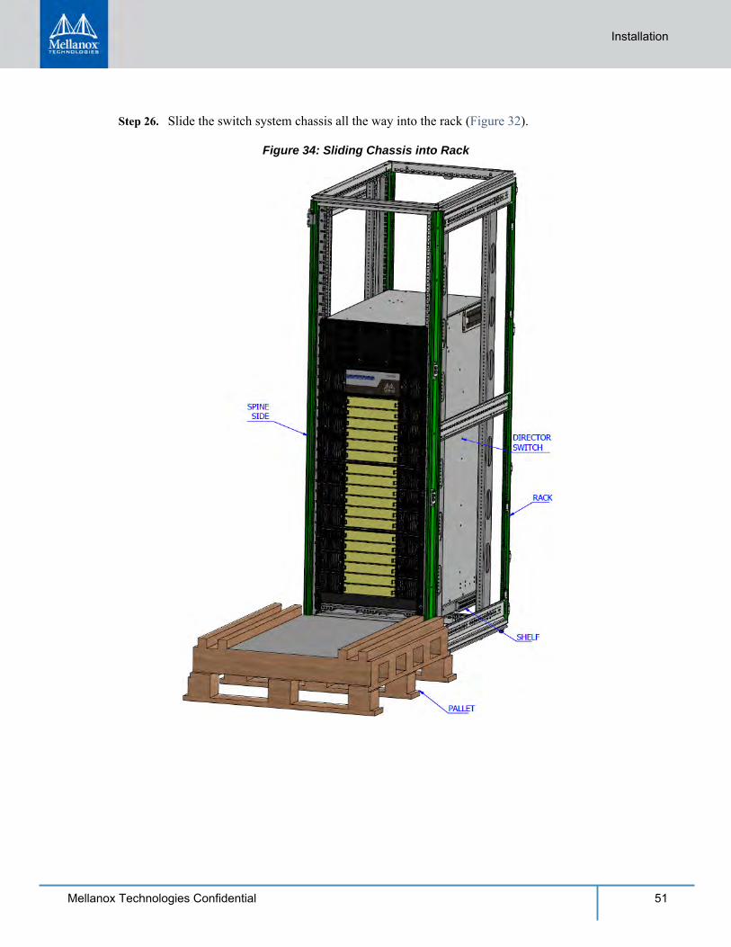
Step 26. Slide the switch system chassis all the way into the rack (Figure 32).
Figure 34: Sliding Chassis into Rack
52 Mellanox Technologies Confidential
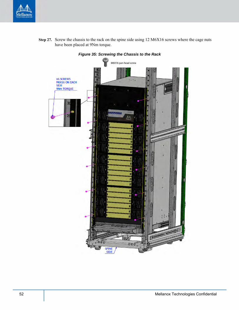
Step 27. Screw the chassis to the rack on the spine side using 12 M6X16 screws where the cage nuts have been placed at 9Nm torque.
Figure 35: Screwing the Chassis to the Rack
Installation
53Mellanox Technologies Confidential
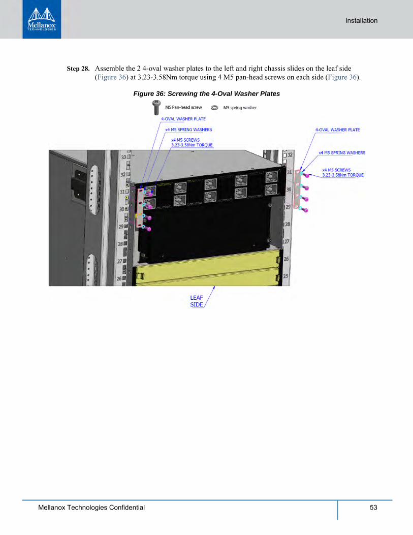
Step 28. Assemble the 2 4-oval washer plates to the left and right chassis slides on the leaf side (Figure 36) at 3.23-3.58Nm torque using 4 M5 pan-head screws on each side (Figure 36).
Figure 36: Screwing the 4-Oval Washer Plates
54 Mellanox Technologies Confidential
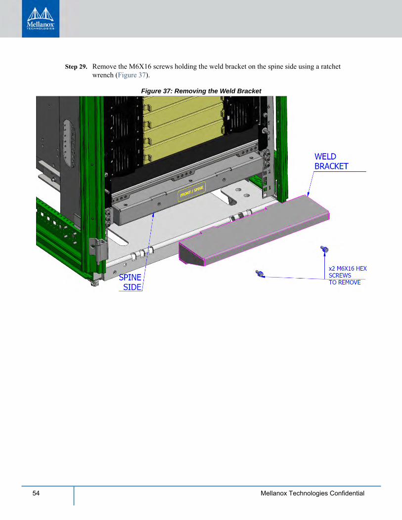
Step 29. Remove the M6X16 screws holding the weld bracket on the spine side using a ratchet wrench (Figure 37).
Figure 37: Removing the Weld Bracket
Installation
55Mellanox Technologies Confidential
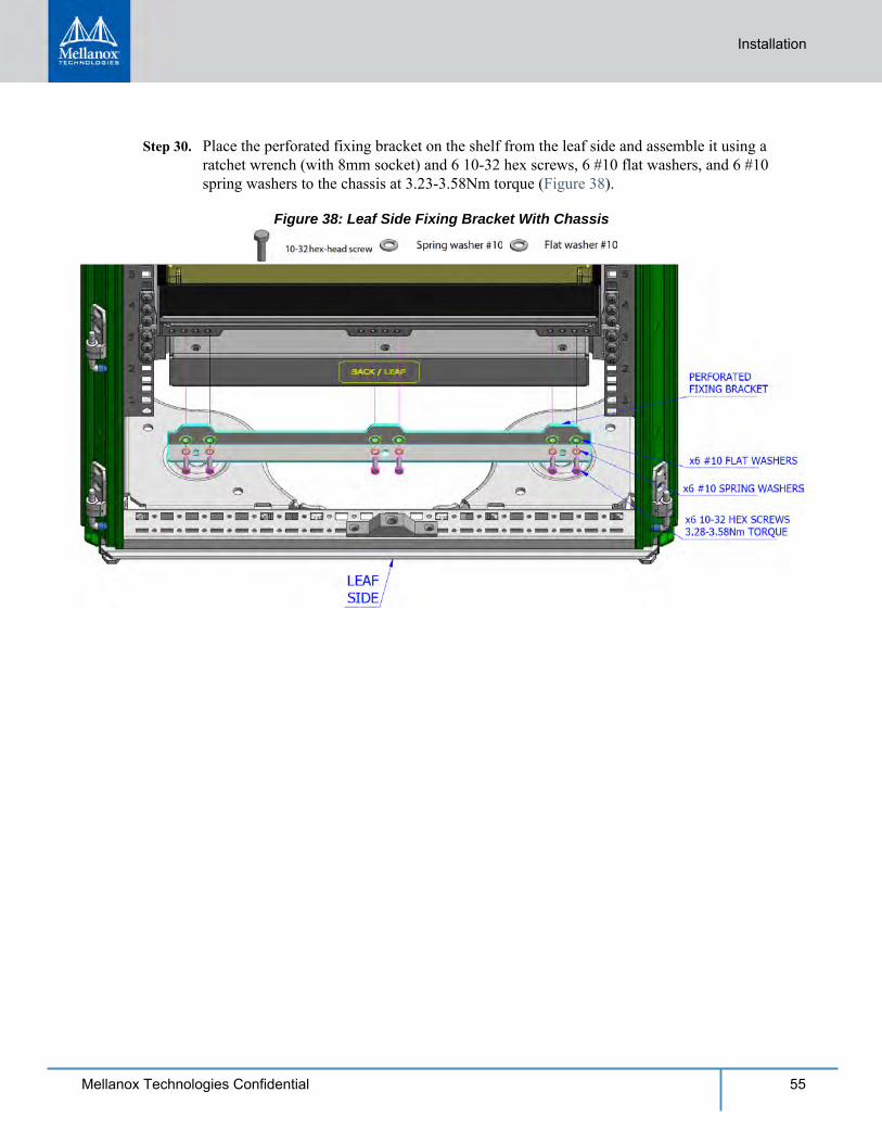
Step 30. Place the perforated fixing bracket on the shelf from the leaf side and assemble it using a ratchet wrench (with 8mm socket) and 6 10-32 hex screws, 6 #10 flat washers, and 6 #10 spring washers to the chassis at 3.23-3.58Nm torque (Figure 38).
Figure 38: Leaf Side Fixing Bracket With Chassis
56 Mellanox Technologies Confidential
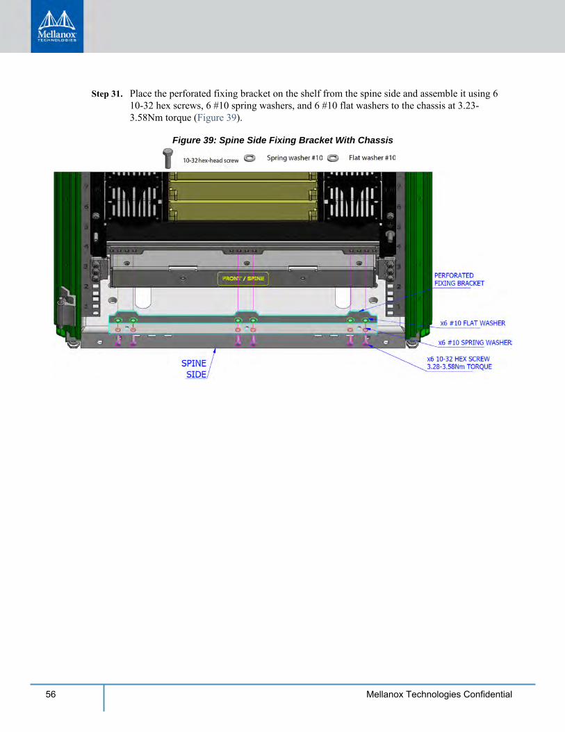
Step 31. Place the perforated fixing bracket on the shelf from the spine side and assemble it using 6 10-32 hex screws, 6 #10 spring washers, and 6 #10 flat washers to the chassis at 3.23-3.58Nm torque (Figure 39).
Figure 39: Spine Side Fixing Bracket With Chassis
Installation
57Mellanox Technologies Confidential
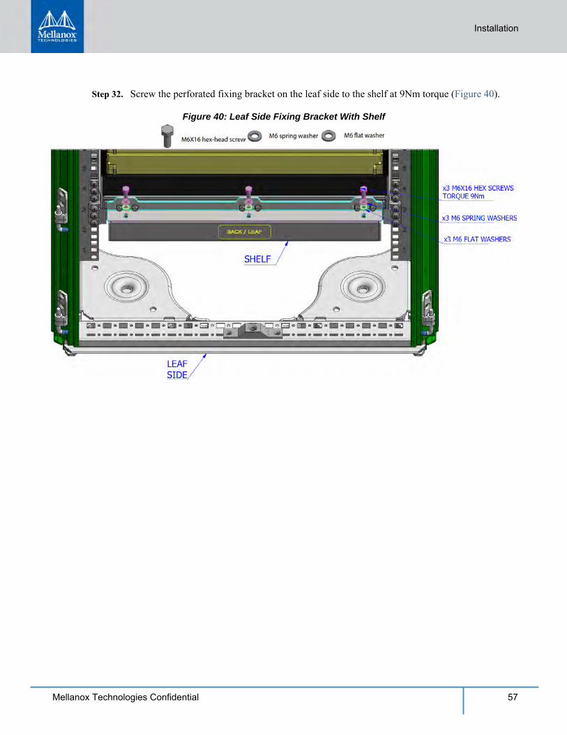
Step 32. Screw the perforated fixing bracket on the leaf side to the shelf at 9Nm torque (Figure 40).
Figure 40: Leaf Side Fixing Bracket With Shelf
58 Mellanox Technologies Confidential
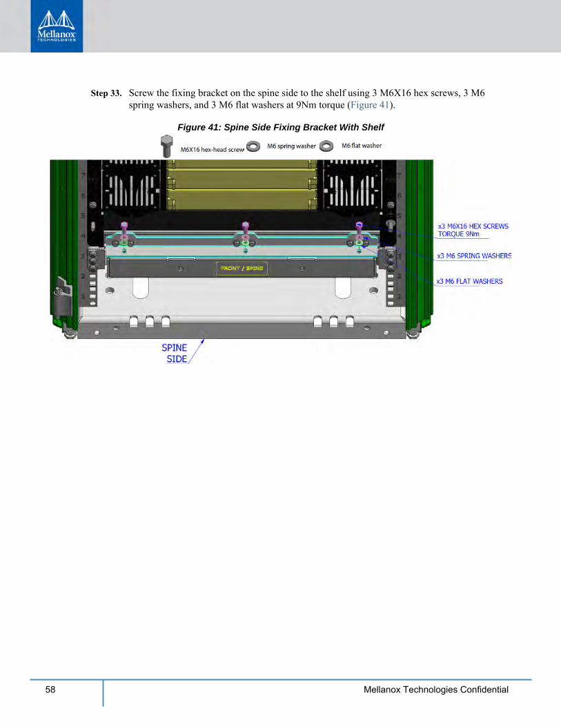
Step 33. Screw the fixing bracket on the spine side to the shelf using 3 M6X16 hex screws, 3 M6 spring washers, and 3 M6 flat washers at 9Nm torque (Figure 41).
Figure 41: Spine Side Fixing Bracket With Shelf
Installation
59Mellanox Technologies Confidential
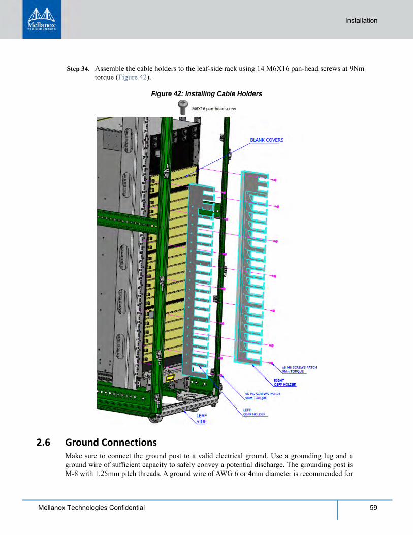
Step 34. Assemble the cable holders to the leaf-side rack using 14 M6X16 pan-head screws at 9Nm torque (Figure 42).
Figure 42: Installing Cable Holders
2.6 Ground ConnectionsMake sure to connect the ground post to a valid electrical ground. Use a grounding lug and a ground wire of sufficient capacity to safely convey a potential discharge. The grounding post is M-8 with 1.25mm pitch threads. A ground wire of AWG 6 or 4mm diameter is recommended for
60 Mellanox Technologies Confidential
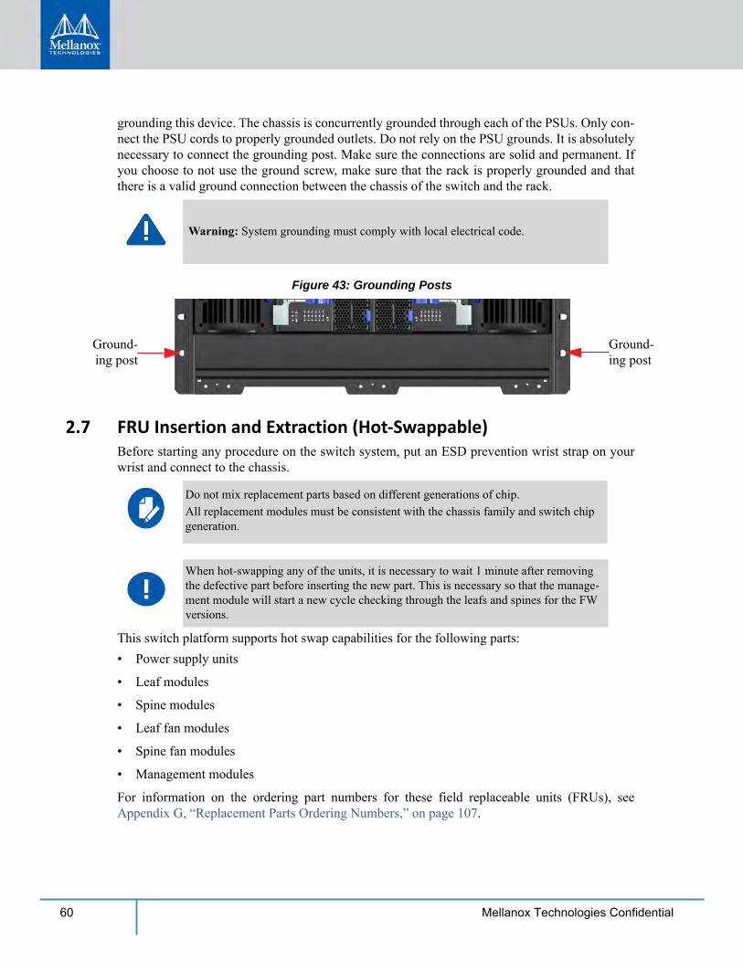
grounding this device. The chassis is concurrently grounded through each of the PSUs. Only con-nect the PSU cords to properly grounded outlets. Do not rely on the PSU grounds. It is absolutely necessary to connect the grounding post. Make sure the connections are solid and permanent. If you choose to not use the ground screw, make sure that the rack is properly grounded and that there is a valid ground connection between the chassis of the switch and the rack.
Figure 43: Grounding Posts
Ground-ing post
Ground-ing post
2.7 FRU Insertion and Extraction (Hot-Swappable)Before starting any procedure on the switch system, put an ESD prevention wrist strap on your wrist and connect to the chassis.
This switch platform supports hot swap capabilities for the following parts:• Power supply units
• Leaf modules
• Spine modules
• Leaf fan modules
• Spine fan modules
• Management modules
For information on the ordering part numbers for these field replaceable units (FRUs), see Appendix G, “Replacement Parts Ordering Numbers,” on page 107.
Warning: System grounding must comply with local electrical code.
Do not mix replacement parts based on different generations of chip.All replacement modules must be consistent with the chassis family and switch chip generation.
When hot-swapping any of the units, it is necessary to wait 1 minute after removing the defective part before inserting the new part. This is necessary so that the manage-ment module will start a new cycle checking through the leafs and spines for the FW versions.
Installation
61Mellanox Technologies Confidential
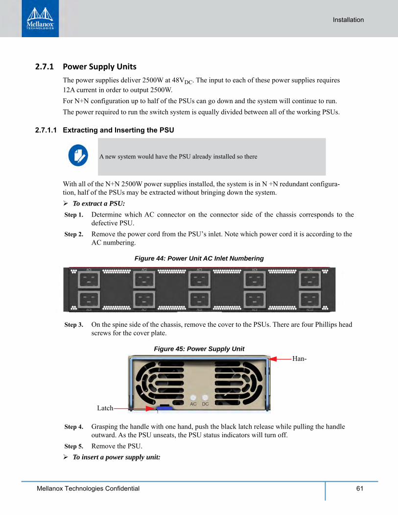
2.7.1 Power Supply UnitsThe power supplies deliver 2500W at 48VDC. The input to each of these power supplies requires 12A current in order to output 2500W.For N+N configuration up to half of the PSUs can go down and the system will continue to run.The power required to run the switch system is equally divided between all of the working PSUs.
2.7.1.1 Extracting and Inserting the PSU
With all of the N+N 2500W power supplies installed, the system is in N +N redundant configura-tion, half of the PSUs may be extracted without bringing down the system. To extract a PSU: Step 1. Determine which AC connector on the connector side of the chassis corresponds to the
defective PSU. Step 2. Remove the power cord from the PSU’s inlet. Note which power cord it is according to the
AC numbering.
Figure 44: Power Unit AC Inlet Numbering
Step 3. On the spine side of the chassis, remove the cover to the PSUs. There are four Phillips head screws for the cover plate.
Figure 45: Power Supply UnitHan-
Latch
Step 4. Grasping the handle with one hand, push the black latch release while pulling the handle outward. As the PSU unseats, the PSU status indicators will turn off.
Step 5. Remove the PSU. To insert a power supply unit:
A new system would have the PSU already installed so there
62 Mellanox Technologies Confidential
Step 1. Make sure the mating connector of the new unit is free of any dirt and/or obstacles. Step 2. Insert the PSU by sliding it into the opening until a slight resistance is felt. Step 3. Continue pressing the PSU until it seats completely. The latch will snap into place confirm-
ing the proper installation. Step 4. Insert the power cord into the supply connector on the other side of the chassis. Step 5. Replace the cover over the PSUs.
2.7.2 Leaf Modules
Leaf module slots are numbered from top to bottom from L1 to L18 on both sides of the chassis.
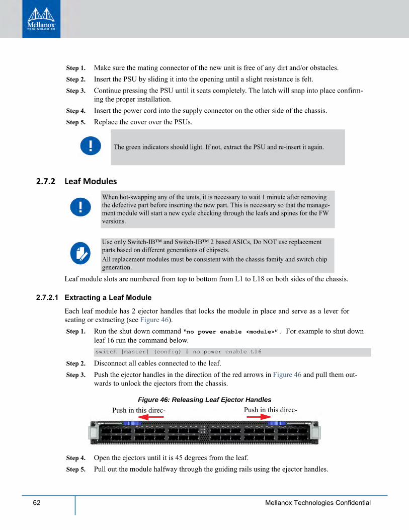
2.7.2.1 Extracting a Leaf Module
Each leaf module has 2 ejector handles that locks the module in place and serve as a lever for seating or extracting (see Figure 46). Step 1. Run the shut down command “no power enable <module>”. For example to shut down
leaf 16 run the command below.switch [master] (config) # no power enable L16
Step 2. Disconnect all cables connected to the leaf. Step 3. Push the ejector handles in the direction of the red arrows in Figure 46 and pull them out-
wards to unlock the ejectors from the chassis.
Figure 46: Releasing Leaf Ejector HandlesPush in this direc- Push in this direc-
Step 4. Open the ejectors until it is 45 degrees from the leaf. Step 5. Pull out the module halfway through the guiding rails using the ejector handles.
The green indicators should light. If not, extract the PSU and re-insert it again.
When hot-swapping any of the units, it is necessary to wait 1 minute after removing the defective part before inserting the new part. This is necessary so that the manage-ment module will start a new cycle checking through the leafs and spines for the FW versions.
Use only Switch-IB™ and Switch-IB™ 2 based ASICs, Do NOT use replacement parts based on different generations of chipsets.All replacement modules must be consistent with the chassis family and switch chip generation.
Installation
63Mellanox Technologies Confidential
Step 6. Re-lock the ejector handles. Step 7. Hold the body of the leaf on both sides and remove it from the chassis.
2.7.2.2 Inserting a Leaf Module
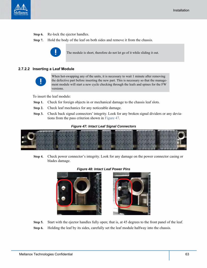
To insert the leaf module: Step 1. Check for foreign objects in or mechanical damage to the chassis leaf slots. Step 2. Check leaf mechanics for any noticeable damage. Step 3. Check back signal connectors’ integrity. Look for any broken signal dividers or any devia-
tions from the pass criterion shown in Figure 47.
Figure 47: Intact Leaf Signal Connectors
Step 4. Check power connector’s integrity. Look for any damage on the power connector casing or blades damage.
Figure 48: Intact Leaf Power Pins
Step 5. Start with the ejector handles fully open; that is, at 45 degrees to the front panel of the leaf. Step 6. Holding the leaf by its sides, carefully set the leaf module halfway into the chassis.
The module is short, therefore do not let go of it while sliding it out.
When hot-swapping any of the units, it is necessary to wait 1 minute after removing the defective part before inserting the new part. This is necessary so that the manage-ment module will start a new cycle checking through the leafs and spines for the FW versions.
64 Mellanox Technologies Confidential
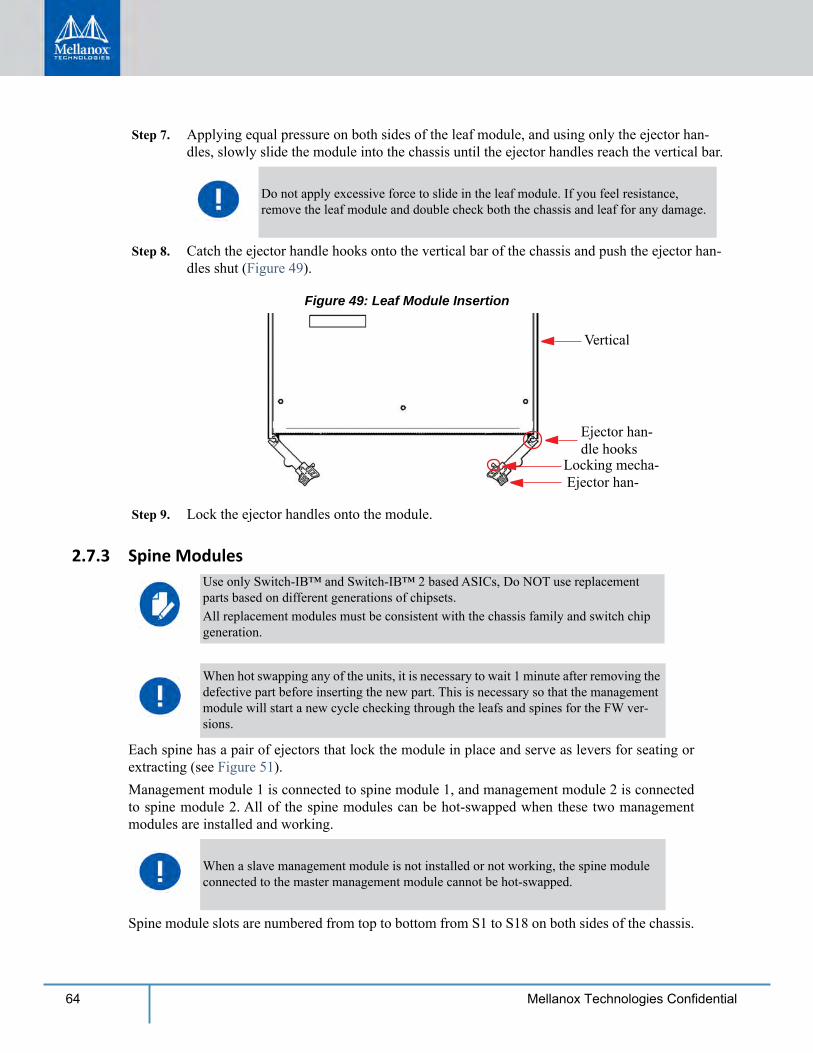
Step 7. Applying equal pressure on both sides of the leaf module, and using only the ejector han-dles, slowly slide the module into the chassis until the ejector handles reach the vertical bar.
Step 8. Catch the ejector handle hooks onto the vertical bar of the chassis and push the ejector han-dles shut (Figure 49).
Figure 49: Leaf Module Insertion
Vertical
Ejector han-dle hooks
Ejector han-Locking mecha-
Step 9. Lock the ejector handles onto the module.
2.7.3 Spine Modules
Each spine has a pair of ejectors that lock the module in place and serve as levers for seating or extracting (see Figure 51).Management module 1 is connected to spine module 1, and management module 2 is connected to spine module 2. All of the spine modules can be hot-swapped when these two management modules are installed and working.
Spine module slots are numbered from top to bottom from S1 to S18 on both sides of the chassis.
Do not apply excessive force to slide in the leaf module. If you feel resistance, remove the leaf module and double check both the chassis and leaf for any damage.
Use only Switch-IB™ and Switch-IB™ 2 based ASICs, Do NOT use replacement parts based on different generations of chipsets.All replacement modules must be consistent with the chassis family and switch chip generation.
When hot swapping any of the units, it is necessary to wait 1 minute after removing the defective part before inserting the new part. This is necessary so that the management module will start a new cycle checking through the leafs and spines for the FW ver-sions.
When a slave management module is not installed or not working, the spine module connected to the master management module cannot be hot-swapped.
Installation
65Mellanox Technologies Confidential
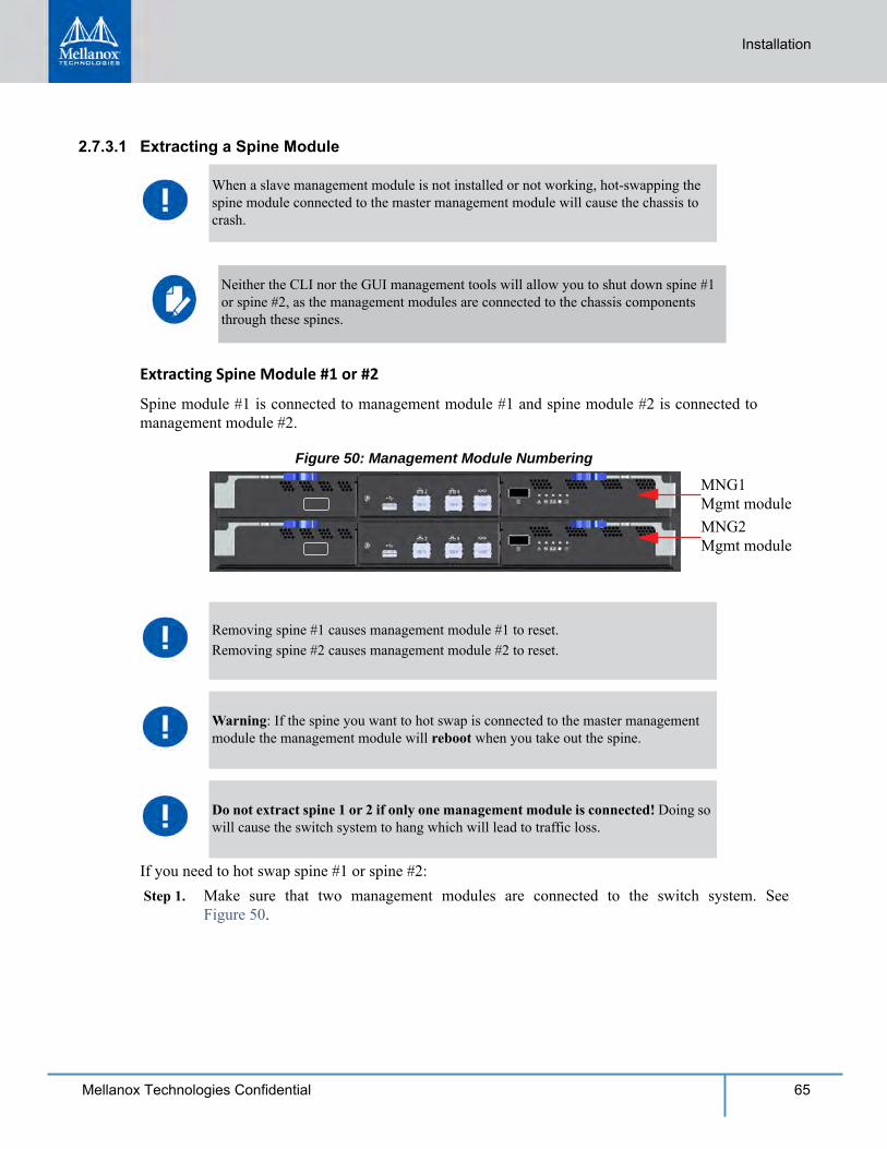
2.7.3.1 Extracting a Spine Module
Extracting Spine Module #1 or #2
Spine module #1 is connected to management module #1 and spine module #2 is connected to management module #2.
Figure 50: Management Module Numbering
MNG2Mgmt module
MNG1Mgmt module
If you need to hot swap spine #1 or spine #2: Step 1. Make sure that two management modules are connected to the switch system. See
Figure 50.
When a slave management module is not installed or not working, hot-swapping the spine module connected to the master management module will cause the chassis to crash.
Neither the CLI nor the GUI management tools will allow you to shut down spine #1 or spine #2, as the management modules are connected to the chassis components through these spines.
Removing spine #1 causes management module #1 to reset.Removing spine #2 causes management module #2 to reset.
Warning: If the spine you want to hot swap is connected to the master management module the management module will reboot when you take out the spine.
Do not extract spine 1 or 2 if only one management module is connected! Doing so will cause the switch system to hang which will lead to traffic loss.
66 Mellanox Technologies Confidential
Step 2. Extract the spine module according to the procedure in “Extracting Spine Modules Except #1 or #2” starting with Step 2 (without running the shutdown command).
Extracting Spine Modules Except #1 or #2
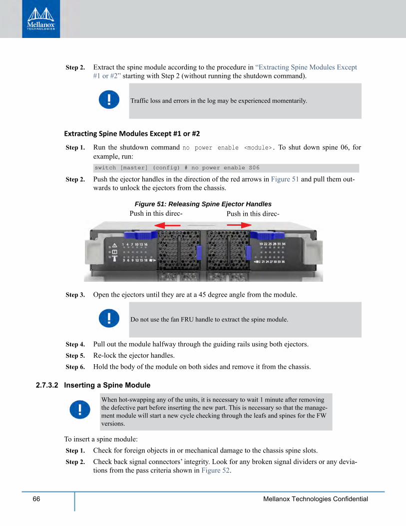
Step 1. Run the shutdown command no power enable <module>. To shut down spine 06, for example, run:switch [master] (config) # no power enable S06
Step 2. Push the ejector handles in the direction of the red arrows in Figure 51 and pull them out-wards to unlock the ejectors from the chassis.
Figure 51: Releasing Spine Ejector HandlesPush in this direc- Push in this direc-
Step 3. Open the ejectors until they are at a 45 degree angle from the module.
Step 4. Pull out the module halfway through the guiding rails using both ejectors. Step 5. Re-lock the ejector handles. Step 6. Hold the body of the module on both sides and remove it from the chassis.
2.7.3.2 Inserting a Spine Module
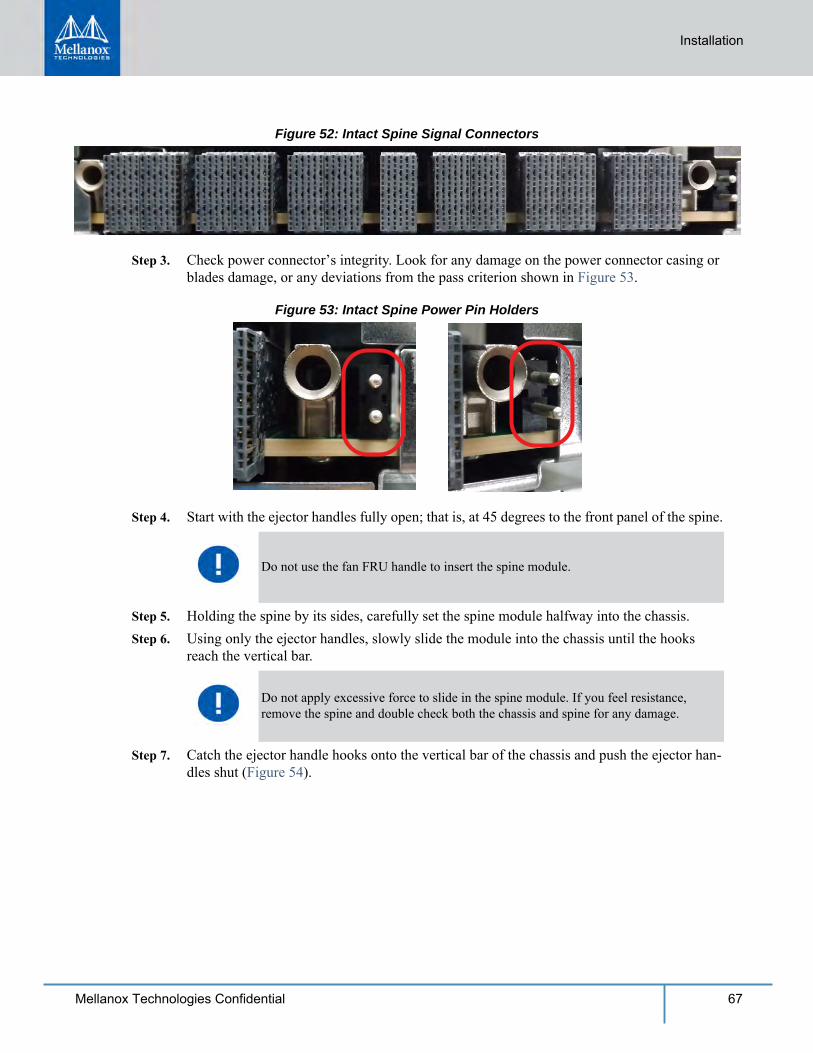
To insert a spine module: Step 1. Check for foreign objects in or mechanical damage to the chassis spine slots. Step 2. Check back signal connectors’ integrity. Look for any broken signal dividers or any devia-
tions from the pass criteria shown in Figure 52.
Traffic loss and errors in the log may be experienced momentarily.
Do not use the fan FRU handle to extract the spine module.
When hot-swapping any of the units, it is necessary to wait 1 minute after removing the defective part before inserting the new part. This is necessary so that the manage-ment module will start a new cycle checking through the leafs and spines for the FW versions.
Installation
67Mellanox Technologies Confidential
Figure 52: Intact Spine Signal Connectors
Step 3. Check power connector’s integrity. Look for any damage on the power connector casing or blades damage, or any deviations from the pass criterion shown in Figure 53.
Figure 53: Intact Spine Power Pin Holders
Step 4. Start with the ejector handles fully open; that is, at 45 degrees to the front panel of the spine.
Step 5. Holding the spine by its sides, carefully set the spine module halfway into the chassis. Step 6. Using only the ejector handles, slowly slide the module into the chassis until the hooks
reach the vertical bar.
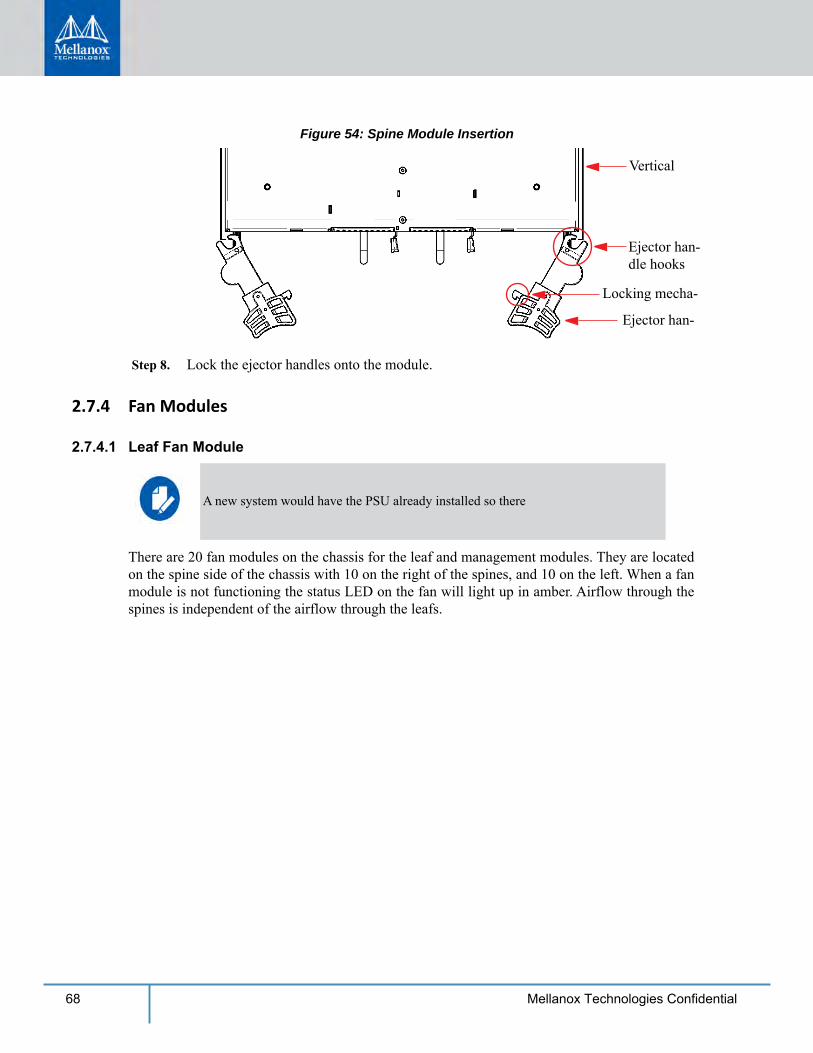
Step 7. Catch the ejector handle hooks onto the vertical bar of the chassis and push the ejector han-dles shut (Figure 54).
Do not use the fan FRU handle to insert the spine module.
Do not apply excessive force to slide in the spine module. If you feel resistance, remove the spine and double check both the chassis and spine for any damage.
68 Mellanox Technologies Confidential
Figure 54: Spine Module Insertion
Vertical
Ejector han-dle hooks
Ejector han-
Locking mecha-
Step 8. Lock the ejector handles onto the module.
2.7.4 Fan Modules
2.7.4.1 Leaf Fan Module
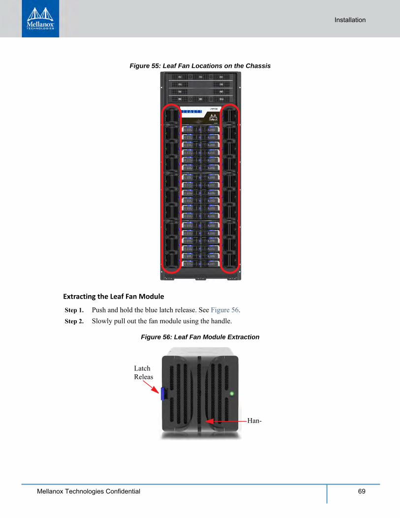
There are 20 fan modules on the chassis for the leaf and management modules. They are located on the spine side of the chassis with 10 on the right of the spines, and 10 on the left. When a fan module is not functioning the status LED on the fan will light up in amber. Airflow through the spines is independent of the airflow through the leafs.
A new system would have the PSU already installed so there
Installation
69Mellanox Technologies Confidential
Figure 55: Leaf Fan Locations on the Chassis
Extracting the Leaf Fan Module
Step 1. Push and hold the blue latch release. See Figure 56. Step 2. Slowly pull out the fan module using the handle.
Figure 56: Leaf Fan Module Extraction
Latch Releas
Han-
70 Mellanox Technologies Confidential
Inserting the Leaf Fan Module
Step 1. Confirm that the location of the connector in the chassis lines up with the connector in the fan module.
Step 2. Slowly slide in the new leaf fan module.
Step 3. Push the fan module until the latch engages. Step 4. Make sure that the green fan LED on the module comes on (indicating that fan is running).
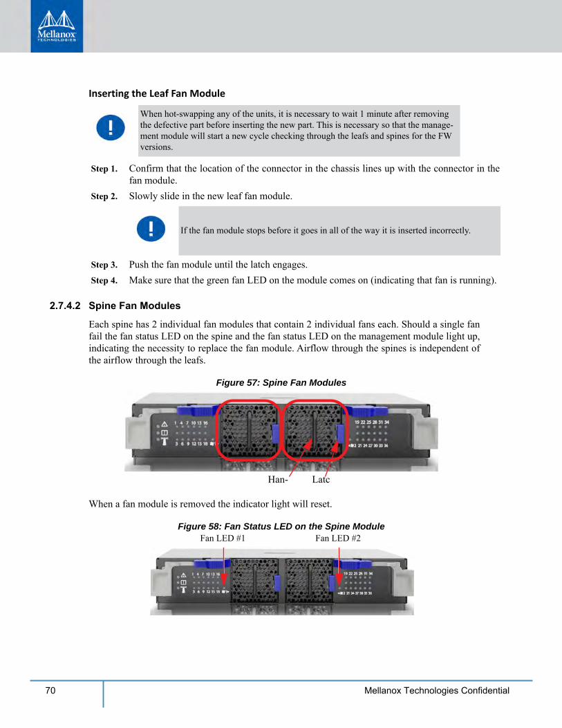
2.7.4.2 Spine Fan Modules
Each spine has 2 individual fan modules that contain 2 individual fans each. Should a single fan fail the fan status LED on the spine and the fan status LED on the management module light up, indicating the necessity to replace the fan module. Airflow through the spines is independent of the airflow through the leafs.
Figure 57: Spine Fan Modules
LatcHan-
When a fan module is removed the indicator light will reset.
Figure 58: Fan Status LED on the Spine ModuleFan LED #1 Fan LED #2
When hot-swapping any of the units, it is necessary to wait 1 minute after removing the defective part before inserting the new part. This is necessary so that the manage-ment module will start a new cycle checking through the leafs and spines for the FW versions.
If the fan module stops before it goes in all of the way it is inserted incorrectly.
Installation
71Mellanox Technologies Confidential
Extracting the Spine Fan Module
To extract the spine fan module push the blue latch button while pulling the fan module out.
Inserting the Spine Fan Module
Step 1. Make sure the fan module is oriented correctly with the release latch on the right. Confirm that the location of the connector in the chassis will line up with the connector in the fan module.
Step 2. Slowly slide in the new spine fan module. Step 3. Push the fan module as far as it will go, make sure the locking latches engage.
2.7.5 Management Module
Extracting a Management Module
Management modules are located on the leaf side, above the leafs. There are two slots to install the management modules.
Each management module has a pair of ejectors that lock the module in place and serve as a lever for seating or extracting (see Figure 59).
When hot-swapping any of the units, it is necessary to wait 1 minute after removing the defective part before inserting the new part. This is necessary so that the manage-ment module will start a new cycle checking through the leafs and spines for the FW versions.
If the fan LED continues to show amber remove the fan module and check the pins on the connector inside of the spine to make sure that none of them are bent.
When hot-swapping any of the units, it is necessary to wait 1 minute after removing the defective part before inserting the new part. This is necessary so that the manage-ment module will start a new cycle checking through the leafs and spines for the FW versions.
Only one management module is required to run the switch system.
If only one management module is used, the other management slot should be covered using a management blank unit.
72 Mellanox Technologies Confidential
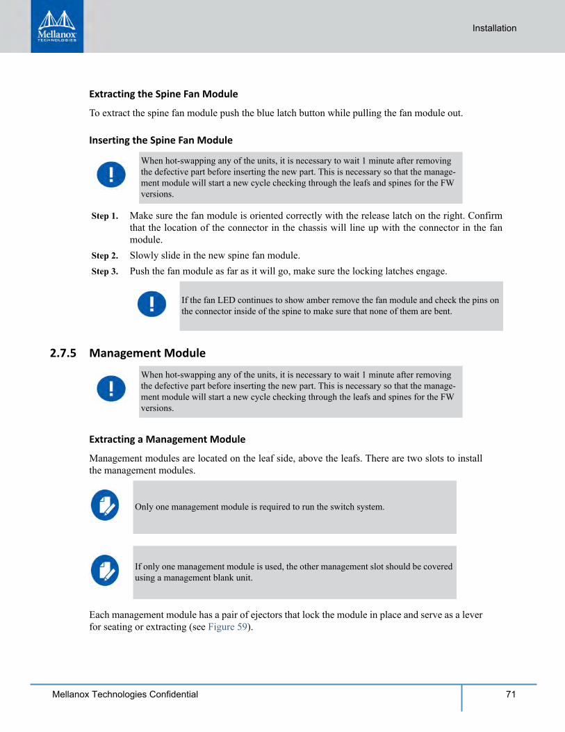
Step 1. Run the shut down command no power enable <module>. For example to shut down management module 2, run. switch [master] (config) # no power enable mgmt2
Step 2. Disconnect all cables connected to the management module. Step 3. Push the ejector handles in the direction of the red arrows in Figure 59 and pull them out-
wards to unlock the ejectors from the chassis.
Figure 59: Releasing Management Ejector HandlesPush in this direc-Push in this direc-
Step 4. Open the ejectors until they are 45 degrees from the module. Step 5. Pull out the module halfway through the guiding rails using the ejector handle. Step 6. Lock the ejector handle. Step 7. Hold the body of the module on both sides and remove it from the chassis.
Inserting a Management Module
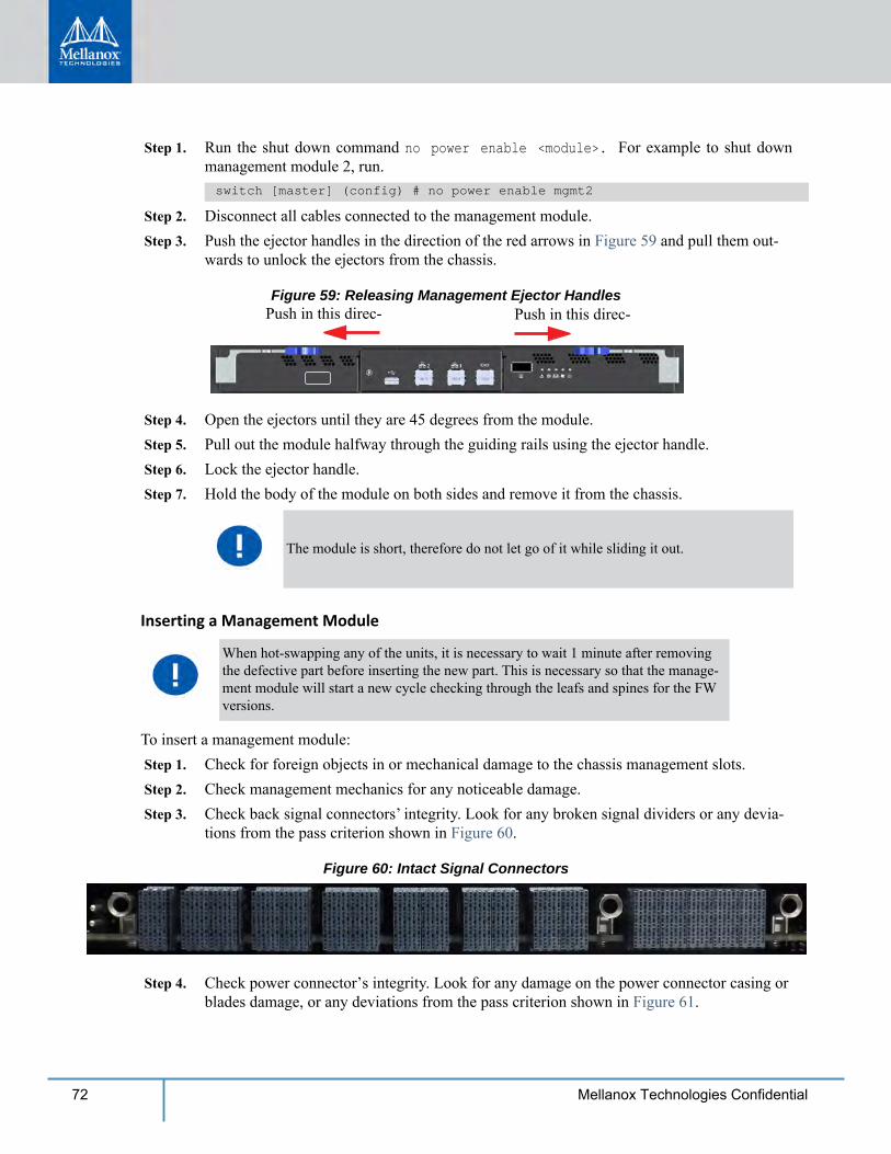
To insert a management module: Step 1. Check for foreign objects in or mechanical damage to the chassis management slots. Step 2. Check management mechanics for any noticeable damage. Step 3. Check back signal connectors’ integrity. Look for any broken signal dividers or any devia-
tions from the pass criterion shown in Figure 60.
Figure 60: Intact Signal Connectors
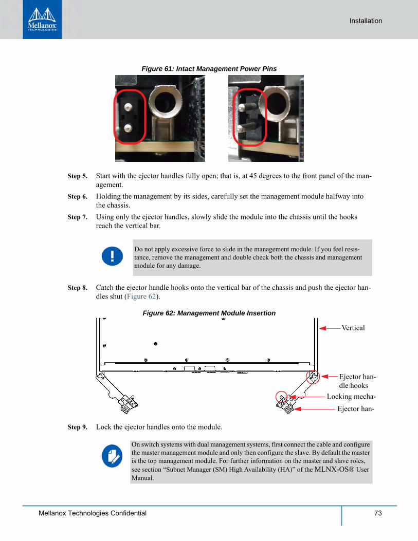
Step 4. Check power connector’s integrity. Look for any damage on the power connector casing or blades damage, or any deviations from the pass criterion shown in Figure 61.
The module is short, therefore do not let go of it while sliding it out.
When hot-swapping any of the units, it is necessary to wait 1 minute after removing the defective part before inserting the new part. This is necessary so that the manage-ment module will start a new cycle checking through the leafs and spines for the FW versions.
Installation
73Mellanox Technologies Confidential
Figure 61: Intact Management Power Pins
Step 5. Start with the ejector handles fully open; that is, at 45 degrees to the front panel of the man-agement.
Step 6. Holding the management by its sides, carefully set the management module halfway into the chassis.
Step 7. Using only the ejector handles, slowly slide the module into the chassis until the hooks reach the vertical bar.
Step 8. Catch the ejector handle hooks onto the vertical bar of the chassis and push the ejector han-dles shut (Figure 62).
Figure 62: Management Module Insertion
Vertical
Ejector han-dle hooks
Ejector han-Locking mecha-
Step 9. Lock the ejector handles onto the module.
Do not apply excessive force to slide in the management module. If you feel resis-tance, remove the management and double check both the chassis and management module for any damage.
On switch systems with dual management systems, first connect the cable and configure the master management module and only then configure the slave. By default the master is the top management module. For further information on the master and slave roles, see section “Subnet Manager (SM) High Availability (HA)” of the MLNX-OS® User Manual.
74 Mellanox Technologies Confidential
2.8 InfiniBand QSFP Cable InstallationThe switch uses industry standard QSFP InfiniBand cables which are available from Mellanox Technologies. The Mellanox proprietary QSFP cables support full 100+100Gb/s (EDR), 56+56Gb/s (FDR), 40+40Gb/s (FDR10), 40+40Gb/s (QDR), 20+20Gb/s (DDR) and 10+10Gb/s (SDR) bidirectional wire speed of the switch ports. All InfiniBand QSFP connections are made to the leaf modules. Each leaf has 18 InfiniBand QSFP connectors in two rows, which are num-bered 1-18. See Section 3.1.7 for port numbering.
All cables can be inserted or removed with the unit powered on. To insert a cable, press the con-nector onto the port receptacle until the connector is firmly seated. The orange LED indicator above the port will light when the physical connection is established (when both ends of the cable are properly connected to working devices). Allow 15 seconds for link to get up. To remove, dis-engage the lock and slowly pull the connector away from the port receptacle.
All management modules in the chassis must go through an initial configuration proce-dure. See the Installation Guide for the initial configuration procedure.
If maximum cable lengths are exceeded data transfer will be reduced and the bit error rate will increase.
EDR is only guaranteed to work with approved Mellanox cables.
For a valid physical connection both ends of the cable must be connected to working devices.
Careful to not impede the airflow through the ventilation holes next to the InfiniBand ports. Use cable lengths which allow routing horizontally around to the side of the chassis before bending upward or downward in the rack.
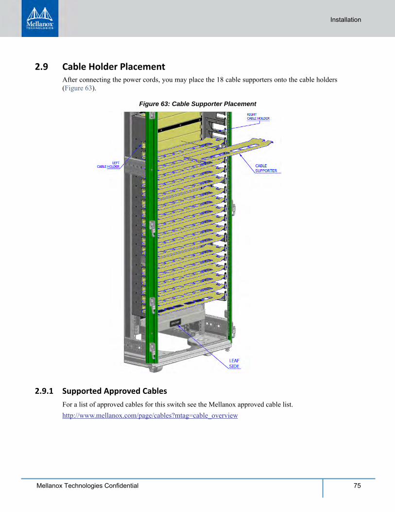
Installation
75Mellanox Technologies Confidential
2.9 Cable Holder PlacementAfter connecting the power cords, you may place the 18 cable supporters onto the cable holders (Figure 63).
Figure 63: Cable Supporter Placement
2.9.1 Supported Approved Cables For a list of approved cables for this switch see the Mellanox approved cable list.http://www.mellanox.com/page/cables?mtag=cable_overview
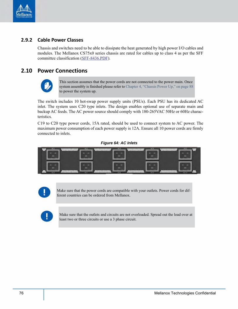
76 Mellanox Technologies Confidential
2.9.2 Cable Power ClassesChassis and switches need to be able to dissipate the heat generated by high power I/O cables and modules. The Mellanox CS75x0 series chassis are rated for cables up to class 4 as per the SFF committee classification (SFF-8436.PDF).
2.10 Power Connections
The switch includes 10 hot-swap power supply units (PSUs). Each PSU has its dedicated AC inlet. The system uses C20 type inlets. The design enables optional use of separate main and backup AC feeds. The AC power source should comply with 180-265VAC 50Hz or 60Hz charac-teristics.C19 to C20 type power cords, 15A rated, should be used to connect system to AC power. The maximum power consumption of each power supply is 12A. Ensure all 10 power cords are firmly connected to inlets.
Figure 64: AC Inlets
This section assumes that the power cords are not connected to the power main. Once system assembly is finished please refer to Chapter 4, “Chassis Power Up,” on page 88 to power the system up.
Make sure that the power cords are compatible with your outlets. Power cords for dif-ferent countries can be ordered from Mellanox.
Make sure that the outlets and circuits are not overloaded. Spread out the load over at least two or three circuits or use a 3 phase circuit.
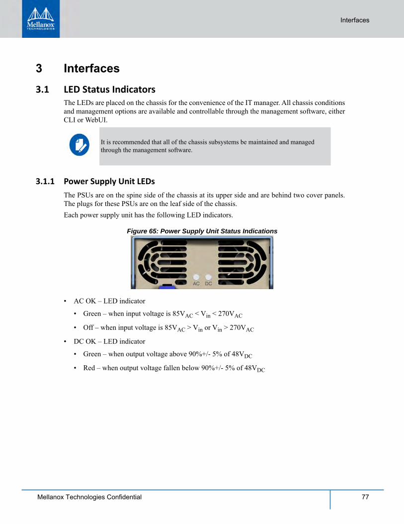
Interfaces
77Mellanox Technologies Confidential
3 Interfaces3.1 LED Status Indicators
The LEDs are placed on the chassis for the convenience of the IT manager. All chassis conditions and management options are available and controllable through the management software, either CLI or WebUI.
3.1.1 Power Supply Unit LEDsThe PSUs are on the spine side of the chassis at its upper side and are behind two cover panels. The plugs for these PSUs are on the leaf side of the chassis. Each power supply unit has the following LED indicators.
Figure 65: Power Supply Unit Status Indications
• AC OK – LED indicator
• Green – when input voltage is 85VAC < Vin < 270VAC
• Off – when input voltage is 85VAC > Vin or Vin > 270VAC
• DC OK – LED indicator
• Green – when output voltage above 90%+/- 5% of 48VDC
• Red – when output voltage fallen below 90%+/- 5% of 48VDC
It is recommended that all of the chassis subsystems be maintained and managed through the management software.
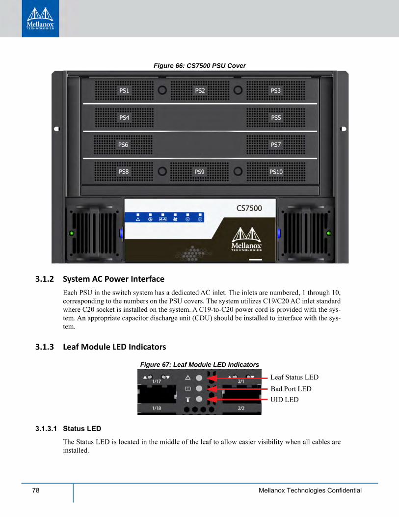
78 Mellanox Technologies Confidential
Figure 66: CS7500 PSU Cover
3.1.2 System AC Power InterfaceEach PSU in the switch system has a dedicated AC inlet. The inlets are numbered, 1 through 10, corresponding to the numbers on the PSU covers. The system utilizes C19/C20 AC inlet standard where C20 socket is installed on the system. A C19-to-C20 power cord is provided with the sys-tem. An appropriate capacitor discharge unit (CDU) should be installed to interface with the sys-tem.
3.1.3 Leaf Module LED Indicators
Figure 67: Leaf Module LED Indicators
Leaf Status LEDBad Port LEDUID LED
3.1.3.1 Status LED
The Status LED is located in the middle of the leaf to allow easier visibility when all cables are installed.
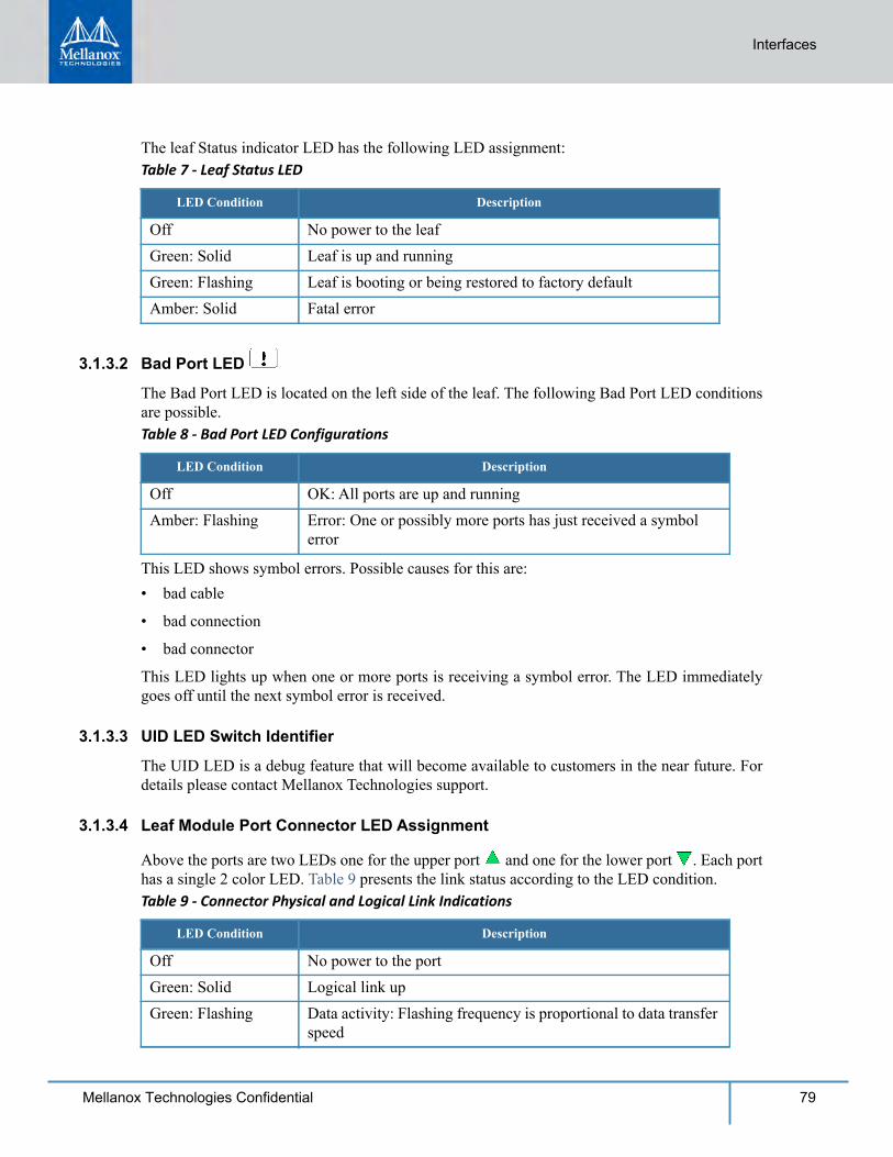
Interfaces
79Mellanox Technologies Confidential
The leaf Status indicator LED has the following LED assignment:Table 7 - Leaf Status LED
LED Condition Description
Off No power to the leafGreen: Solid Leaf is up and runningGreen: Flashing Leaf is booting or being restored to factory defaultAmber: Solid Fatal error
3.1.3.2 Bad Port LED
The Bad Port LED is located on the left side of the leaf. The following Bad Port LED conditions are possible.Table 8 - Bad Port LED Configurations
LED Condition Description
Off OK: All ports are up and runningAmber: Flashing Error: One or possibly more ports has just received a symbol
error
This LED shows symbol errors. Possible causes for this are:• bad cable
• bad connection
• bad connector
This LED lights up when one or more ports is receiving a symbol error. The LED immediately goes off until the next symbol error is received.
3.1.3.3 UID LED Switch Identifier
The UID LED is a debug feature that will become available to customers in the near future. For details please contact Mellanox Technologies support.
3.1.3.4 Leaf Module Port Connector LED Assignment
Above the ports are two LEDs one for the upper port and one for the lower port . Each port has a single 2 color LED. Table 9 presents the link status according to the LED condition.Table 9 - Connector Physical and Logical Link Indications
LED Condition Description
Off No power to the portGreen: Solid Logical link upGreen: Flashing Data activity: Flashing frequency is proportional to data transfer
speed
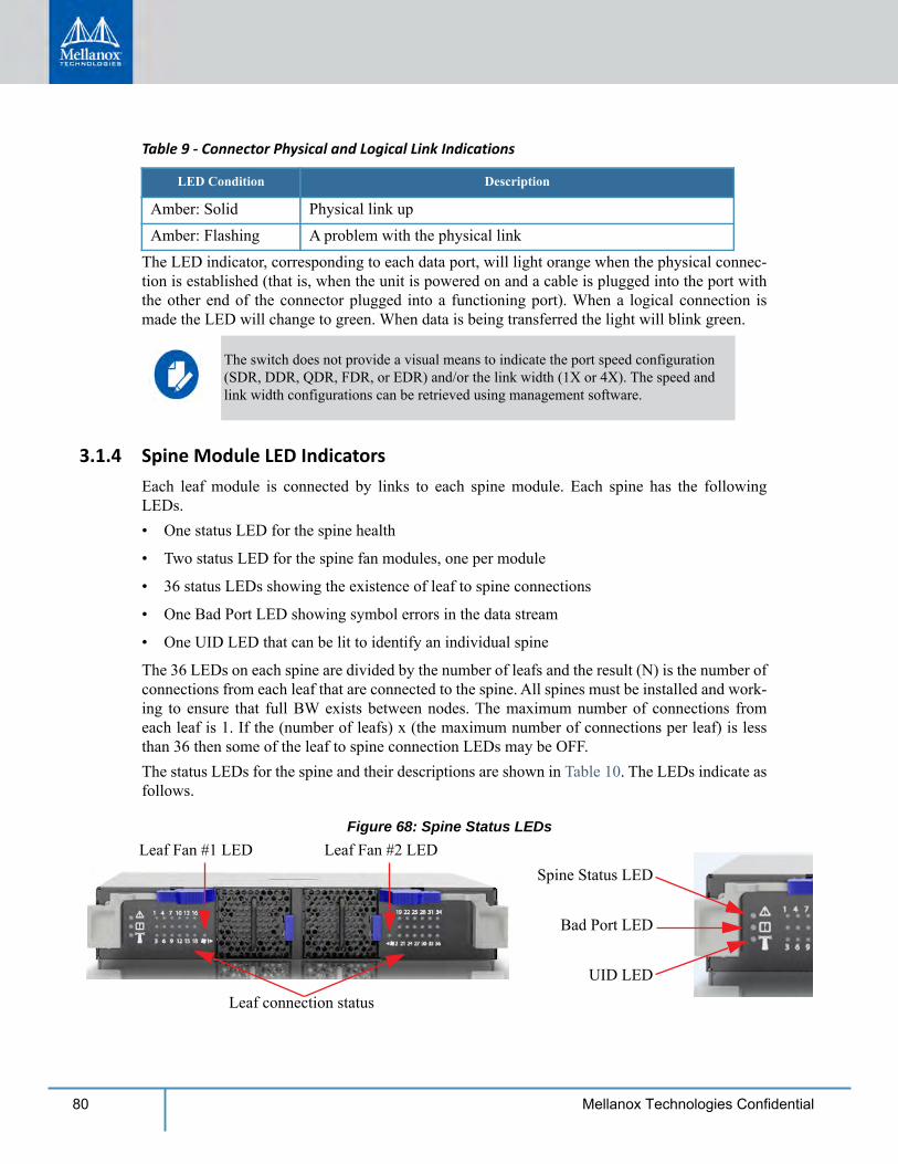
80 Mellanox Technologies Confidential
The LED indicator, corresponding to each data port, will light orange when the physical connec-tion is established (that is, when the unit is powered on and a cable is plugged into the port with the other end of the connector plugged into a functioning port). When a logical connection is made the LED will change to green. When data is being transferred the light will blink green.
3.1.4 Spine Module LED IndicatorsEach leaf module is connected by links to each spine module. Each spine has the following LEDs.• One status LED for the spine health
• Two status LED for the spine fan modules, one per module
• 36 status LEDs showing the existence of leaf to spine connections
• One Bad Port LED showing symbol errors in the data stream
• One UID LED that can be lit to identify an individual spine
The 36 LEDs on each spine are divided by the number of leafs and the result (N) is the number of connections from each leaf that are connected to the spine. All spines must be installed and work-ing to ensure that full BW exists between nodes. The maximum number of connections from each leaf is 1. If the (number of leafs) x (the maximum number of connections per leaf) is less than 36 then some of the leaf to spine connection LEDs may be OFF.The status LEDs for the spine and their descriptions are shown in Table 10. The LEDs indicate as follows.
Figure 68: Spine Status LEDs
Leaf connection status
Spine Status LED
Bad Port LED
UID LED
Leaf Fan #1 LED Leaf Fan #2 LED
Amber: Solid Physical link upAmber: Flashing A problem with the physical link
The switch does not provide a visual means to indicate the port speed configuration (SDR, DDR, QDR, FDR, or EDR) and/or the link width (1X or 4X). The speed and link width configurations can be retrieved using management software.
Table 9 - Connector Physical and Logical Link Indications
LED Condition Description
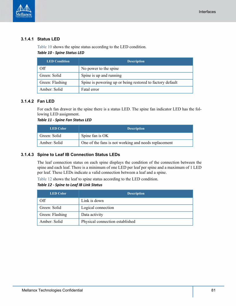
Interfaces
81Mellanox Technologies Confidential
3.1.4.1 Status LED
Table 10 shows the spine status according to the LED condition.Table 10 - Spine Status LED
LED Condition Description
Off No power to the spineGreen: Solid Spine is up and runningGreen: Flashing Spine is powering up or being restored to factory defaultAmber: Solid Fatal error
3.1.4.2 Fan LED
For each fan drawer in the spine there is a status LED. The spine fan indicator LED has the fol-lowing LED assignment.Table 11 - Spine Fan Status LED
LED Color Description
Green: Solid Spine fan is OKAmber: Solid One of the fans is not working and needs replacement
3.1.4.3 Spine to Leaf IB Connection Status LEDs
The leaf connection status on each spine displays the condition of the connection between the spine and each leaf. There is a minimum of one LED per leaf per spine and a maximum of 1 LED per leaf. These LEDs indicate a valid connection between a leaf and a spine.Table 12 shows the leaf to spine status according to the LED condition.Table 12 - Spine to Leaf IB Link Status
LED Color Description
Off Link is downGreen: Solid Logical connectionGreen: Flashing Data activityAmber: Solid Physical connection established
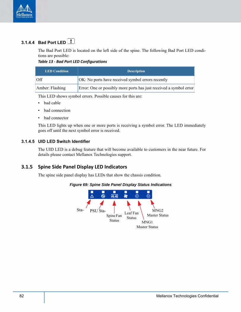
82 Mellanox Technologies Confidential
3.1.4.4 Bad Port LED
The Bad Port LED is located on the left side of the spine. The following Bad Port LED condi-tions are possible:Table 13 - Bad Port LED Configurations
LED Condition Description
Off OK: No ports have received symbol errors recently
Amber: Flashing Error: One or possibly more ports has just received a symbol error
This LED shows symbol errors. Possible causes for this are:• bad cable
• bad connection
• bad connector
This LED lights up when one or more ports is receiving a symbol error. The LED immediately goes off until the next symbol error is received.
3.1.4.5 UID LED Switch Identifier
The UID LED is a debug feature that will become available to customers in the near future. For details please contact Mellanox Technologies support.
3.1.5 Spine Side Panel Display LED IndicatorsThe spine side panel display has LEDs that show the chassis condition.
Figure 69: Spine Side Panel Display Status Indications
Sta- PSU Sta-Spine Fan
Status
Leaf Fan Status
MNG1 Master Status
MNG2 Master Status
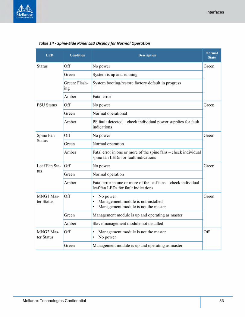
Table 14 - Spine-Side Panel LED Display for Normal Operation
LED Condition Description Normal State
Status Off No power Green
Green System is up and running
Green: Flash-ing
System booting/restore factory default in progress
Amber Fatal error
PSU Status Off No power Green
Green Normal operational
Amber PS fault detected – check individual power supplies for fault indications
Spine Fan Status
Off No power Green
Green Normal operation
Amber Fatal error in one or more of the spine fans – check individual spine fan LEDs for fault indications
Leaf Fan Sta-tus
Off No power Green
Green Normal operation
Amber Fatal error in one or more of the leaf fans – check individual leaf fan LEDs for fault indications
MNG1 Mas-ter Status
Off • No power• Management module is not installed• Management module is not the master
Green
Green Management module is up and operating as master
Amber Slave management module not installed
MNG2 Mas-ter Status
Off • Management module is not the master• No power
Off
Green Management module is up and operating as master
Interfaces
83Mellanox Technologies Confidential
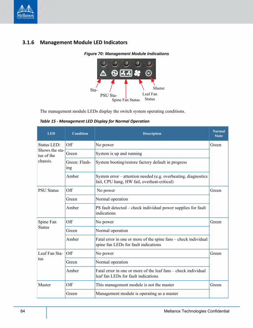
84 Mellanox Technologies Confidential
3.1.6 Management Module LED Indicators
Figure 70: Management Module Indications
Sta-PSU Sta-
Spine Fan StatusLeaf Fan
Status
Master
The management module LEDs display the switch system operating conditions.
Table 15 - Management LED Display for Normal Operation
LED Condition Description Normal State
Status LED:Shows the sta-tus of the chassis.
Off No power Green
Green System is up and running
Green: Flash-ing
System booting/restore factory default in progress
Amber System error – attention needed (e.g. overheating, diagnostics fail, CPU hang, HW fail, overheat-critical)
PSU Status Off No power Green
Green Normal operation
Amber PS fault detected – check individual power supplies for fault indications
Spine Fan Status
Off No power Green
Green Normal operation
Amber Fatal error in one or more of the spine fans – check individual spine fan LEDs for fault indications
Leaf Fan Sta-tus
Off No power Green
Green Normal operation
Amber Fatal error in one or more of the leaf fans – check individual leaf fan LEDs for fault indications
Master Off This management module is not the master Green
Green Management module is operating as a master
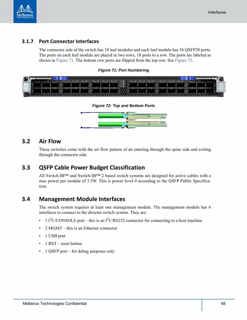
Interfaces
85Mellanox Technologies Confidential
3.1.7 Port Connector InterfacesThe connector side of the switch has 18 leaf modules and each leaf module has 36 QSFP28 ports. The ports on each leaf module are placed in two rows, 18 ports to a row. The ports are labeled as shown in Figure 71. The bottom row ports are flipped from the top row. See Figure 72.
Figure 71: Port Numbering
Figure 72: Top and Bottom Ports
3.2 Air FlowThese switches come with the air flow pattern of air entering through the spine side and exiting through the connector side.
3.3 QSFP Cable Power Budget ClassificationAll Switch-IB™ and Switch-IB™ 2 based switch systems are designed for active cables with a max power per module of 3.5W. This is power level 4 according to the QSFP Public Specifica-tion.
3.4 Management Module InterfacesThe switch system requires at least one management module. The management module has 6 interfaces to connect to the director switch system. They are:
• 1 I2C/CONSOLE port – this is an I2C/RS232 connector for connecting to a host machine
• 2 MGMT – this is an Ethernet connector
• 1 USB port
• 1 RST – reset button
• 1 QSFP port – for debug purposes only
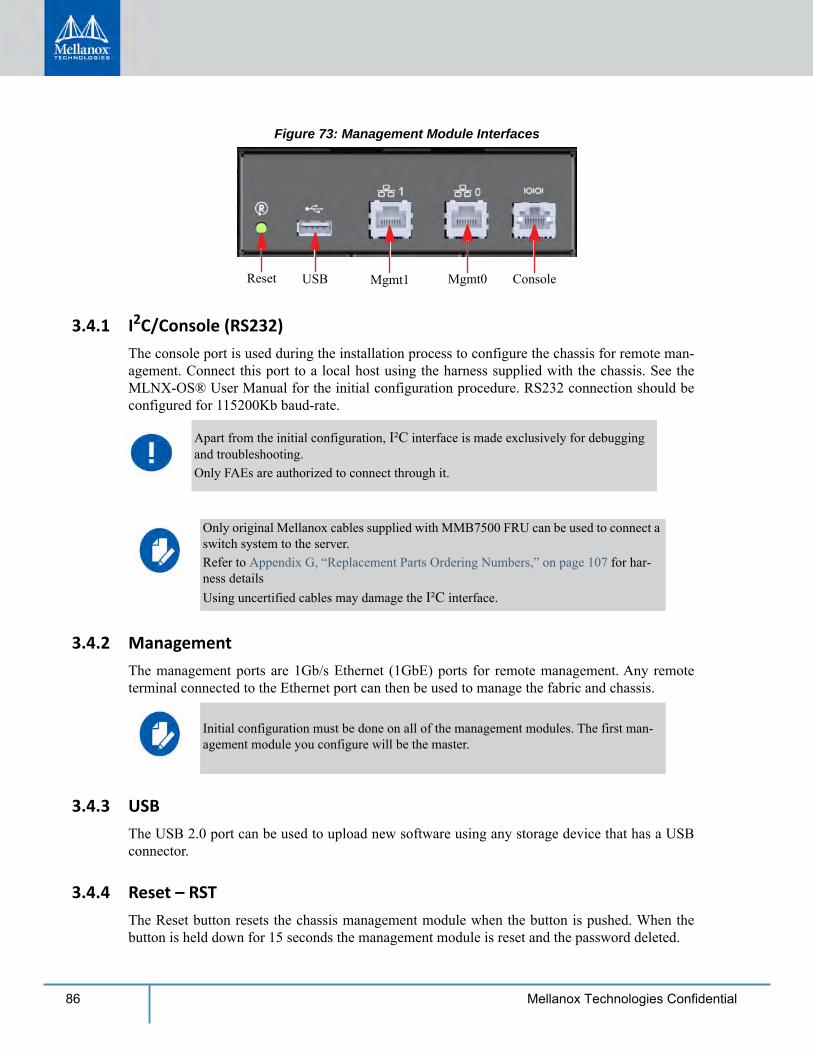
86 Mellanox Technologies Confidential
Figure 73: Management Module Interfaces
Mgmt0Mgmt1USBReset Console
3.4.1 I2C/Console (RS232)The console port is used during the installation process to configure the chassis for remote man-agement. Connect this port to a local host using the harness supplied with the chassis. See the MLNX-OS® User Manual for the initial configuration procedure. RS232 connection should be configured for 115200Kb baud-rate.
3.4.2 ManagementThe management ports are 1Gb/s Ethernet (1GbE) ports for remote management. Any remote terminal connected to the Ethernet port can then be used to manage the fabric and chassis.
3.4.3 USBThe USB 2.0 port can be used to upload new software using any storage device that has a USB connector.
3.4.4 Reset – RSTThe Reset button resets the chassis management module when the button is pushed. When the button is held down for 15 seconds the management module is reset and the password deleted.
Apart from the initial configuration, I²C interface is made exclusively for debugging and troubleshooting. Only FAEs are authorized to connect through it.
Only original Mellanox cables supplied with MMB7500 FRU can be used to connect a switch system to the server. Refer to Appendix G, “Replacement Parts Ordering Numbers,” on page 107 for har-ness detailsUsing uncertified cables may damage the I²C interface.
Initial configuration must be done on all of the management modules. The first man-agement module you configure will be the master.
Interfaces
87Mellanox Technologies Confidential
On a switch system with two management modules, the slave management module must be extracted, then the aforementioned procedure must be performed on the master management module. Once the system reloads, the slave management module may be reinserted.
This button resets the CPU of the management module. A quick push of this button performs this reset. When the reset button is pushed on the master management module this management mod-ule is reset becoming the slave and the other management module becomes the master. If there is only one management module in the chassis all of the leafs and ports are reset by bringing them down and powering them up when the reset button is pushed. When the button is held down for 15 seconds the management module is reset and the password is deleted. You will then be able to enter without a password and make a new password for the user “admin”.
Do not use a sharp pointed object such as needle or push pin for pressing the Reset but-ton. Sharp objects can cause damage, use a flat object such as a paper clip.
88 Mellanox Technologies Confidential
4 Chassis Power Up
With N+N PSU redundancy the chassis must be started with a full complement of possible PSUs, thereafter it can run on half of the total number of PSUs. Connecting the PSUs to different AC lines provides AC failover protection.The system should continue to run and allow a hot swap of a defective PSU. Should there not be enough power to keep all of the leafs running, MLNX-OS® may power down some leafs. If this happens it will be necessary to reboot the chassis once the defective PSU has been replaced.1. Check all FRUs for proper insertion and seating before connecting the AC power cords.
• Power supplies
• Leaf fan modules
• Spine modules
• Spine fan modules
2. Insert all leafs that you plan to use in the chassis.3. Insert thermal blanks in unused leaf and management slots to maintain balanced air flow.4. Connect the power cords to the PSUs.5. Connect the power cords to grounded electrical outlets.
4.1 System Status After Power Up
As system boot been completed you should observe the following: Step 1. PSU AC OK and DC OK indicators are green. Step 2. That the Status LED on each spine, leaf, and management module are green which indicates
that the power supplies are good. Step 3. Spine module indicators display the status of internal links to the installed leaf modules. All
PHY links to existing leafs should be ON. Step 4. Check the spine LEDs and make sure they coincide with Figure 74.
Before starting any procedure on the director switch system put an ESD prevention wrist strap on your wrist and connect to the chassis.
A fully loaded CS7500 series switch system can draw 13.53kW of power. Make sure that the outlets and circuits will not be overloaded. Spread out the load over at least two or three circuits, or a 3 phase supply.
It can take around 5 minutes for the system to boot up. Turn off the system if any LEDs remain amber for more than 7 minutes.
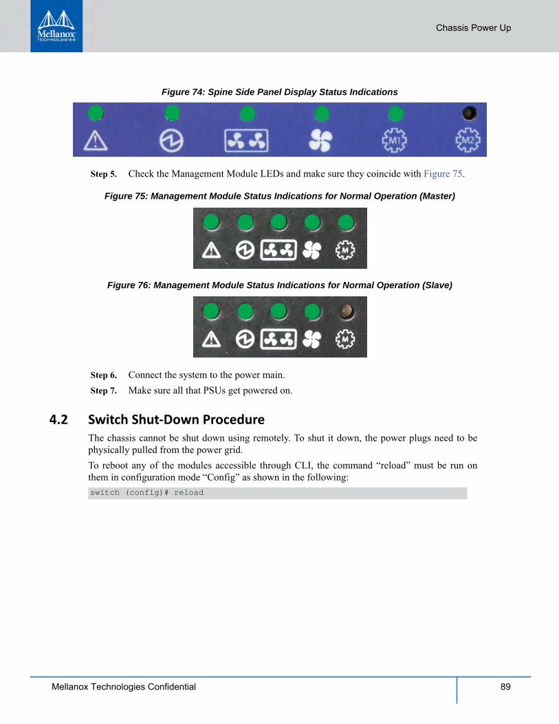
Chassis Power Up
89Mellanox Technologies Confidential
Figure 74: Spine Side Panel Display Status Indications
Step 5. Check the Management Module LEDs and make sure they coincide with Figure 75.
Figure 75: Management Module Status Indications for Normal Operation (Master)
Figure 76: Management Module Status Indications for Normal Operation (Slave)
Step 6. Connect the system to the power main. Step 7. Make sure all that PSUs get powered on.
4.2 Switch Shut-Down ProcedureThe chassis cannot be shut down using remotely. To shut it down, the power plugs need to be physically pulled from the power grid.To reboot any of the modules accessible through CLI, the command “reload” must be run on them in configuration mode “Config” as shown in the following:switch (config)# reload
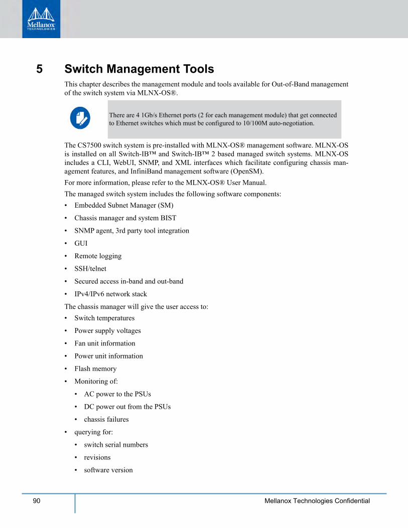
90 Mellanox Technologies Confidential
5 Switch Management ToolsThis chapter describes the management module and tools available for Out-of-Band management of the switch system via MLNX-OS®.
The CS7500 switch system is pre-installed with MLNX-OS® management software. MLNX-OS is installed on all Switch-IB™ and Switch-IB™ 2 based managed switch systems. MLNX-OS includes a CLI, WebUI, SNMP, and XML interfaces which facilitate configuring chassis man-agement features, and InfiniBand management software (OpenSM).For more information, please refer to the MLNX-OS® User Manual.The managed switch system includes the following software components:• Embedded Subnet Manager (SM)
• Chassis manager and system BIST
• SNMP agent, 3rd party tool integration
• GUI
• Remote logging
• SSH/telnet
• Secured access in-band and out-band
• IPv4/IPv6 network stack
The chassis manager will give the user access to: • Switch temperatures
• Power supply voltages
• Fan unit information
• Power unit information
• Flash memory
• Monitoring of:
• AC power to the PSUs
• DC power out from the PSUs
• chassis failures
• querying for:
• switch serial numbers
• revisions
• software version
There are 4 1Gb/s Ethernet ports (2 for each management module) that get connected to Ethernet switches which must be configured to 10/100M auto-negotiation.
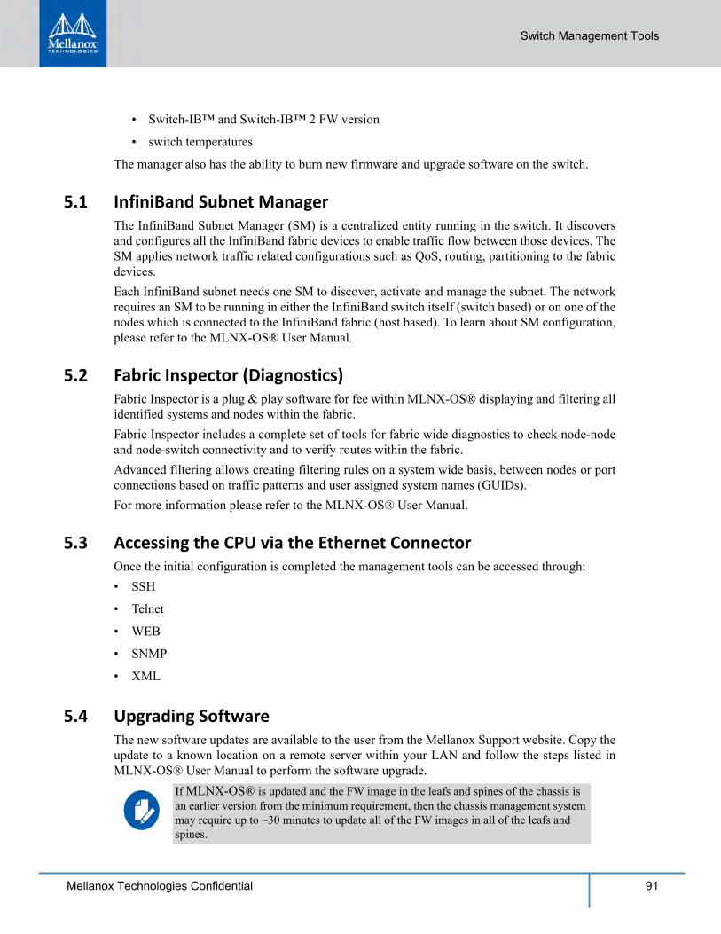
Switch Management Tools
91Mellanox Technologies Confidential
• Switch-IB™ and Switch-IB™ 2 FW version
• switch temperatures
The manager also has the ability to burn new firmware and upgrade software on the switch.
5.1 InfiniBand Subnet ManagerThe InfiniBand Subnet Manager (SM) is a centralized entity running in the switch. It discovers and configures all the InfiniBand fabric devices to enable traffic flow between those devices. The SM applies network traffic related configurations such as QoS, routing, partitioning to the fabric devices.Each InfiniBand subnet needs one SM to discover, activate and manage the subnet. The network requires an SM to be running in either the InfiniBand switch itself (switch based) or on one of the nodes which is connected to the InfiniBand fabric (host based). To learn about SM configuration, please refer to the MLNX-OS® User Manual.
5.2 Fabric Inspector (Diagnostics)Fabric Inspector is a plug & play software for fee within MLNX-OS® displaying and filtering all identified systems and nodes within the fabric.Fabric Inspector includes a complete set of tools for fabric wide diagnostics to check node-node and node-switch connectivity and to verify routes within the fabric.Advanced filtering allows creating filtering rules on a system wide basis, between nodes or port connections based on traffic patterns and user assigned system names (GUIDs).For more information please refer to the MLNX-OS® User Manual.
5.3 Accessing the CPU via the Ethernet ConnectorOnce the initial configuration is completed the management tools can be accessed through:• SSH
• Telnet
• WEB
• SNMP
• XML
5.4 Upgrading SoftwareThe new software updates are available to the user from the Mellanox Support website. Copy the update to a known location on a remote server within your LAN and follow the steps listed in MLNX-OS® User Manual to perform the software upgrade.
If MLNX-OS® is updated and the FW image in the leafs and spines of the chassis is an earlier version from the minimum requirement, then the chassis management system may require up to ~30 minutes to update all of the FW images in all of the leafs and spines.
92 Mellanox Technologies Confidential
6 Troubleshooting6.1 Power Supply Unit
As each PSU is plugged in, make sure that the green power LEDs on the PSU comes on.Issue 1. If the AC power LED is off
1. Check that the power cable is the correct power cable for your country.2. Check that the power cable is plugged into a working outlet.3. Check that the power cable has a voltage within the range of 180-240 volts AC.4. Remove and reinstall the power cable.5. Check the circuit breakers to be sure that the breaker has not tripped.6. Check that the power cable is good. Replace the power cable.7. If the AC power LED is green but the DC power LED amber, replace the PSU.8. Make sure the power supply is inserted.
6.2 Leaf ModuleIssue 1. The power LED for the leaf module is off
1. Make sure that all of the PSUs are showing DC OK.2. Uninstall and reinstall the Leaf module.3. When the amber LED is on, this indicates a fault in the module, uninstall and reinstall the leaf
module.4. If uninstalling and reinstalling the leaf module does not work, burn the latest FW on the leaf
module and uninstall and reinstall the leaf module.5. Replace the leaf module with a new one.
Issue 2. The physical link LED for the InfiniBand connector does not come on
1. Check that both ends of the cable are connected.2. Check that the locks on the ends are secured.3. Make sure that the latest FW version is installed on both the HCA card and the switch.4. If media adapters are used check that the all connections are good, tight, and secure.5. Replace the cable.Issue 3. The activity indication does not come on
If the Power supplies cannot supply enough power, the management module may shut down the some leafs.
Should any of the modules shut down due to over temperature, wait 5 minutes and then follow the procedure starting with Step 2.
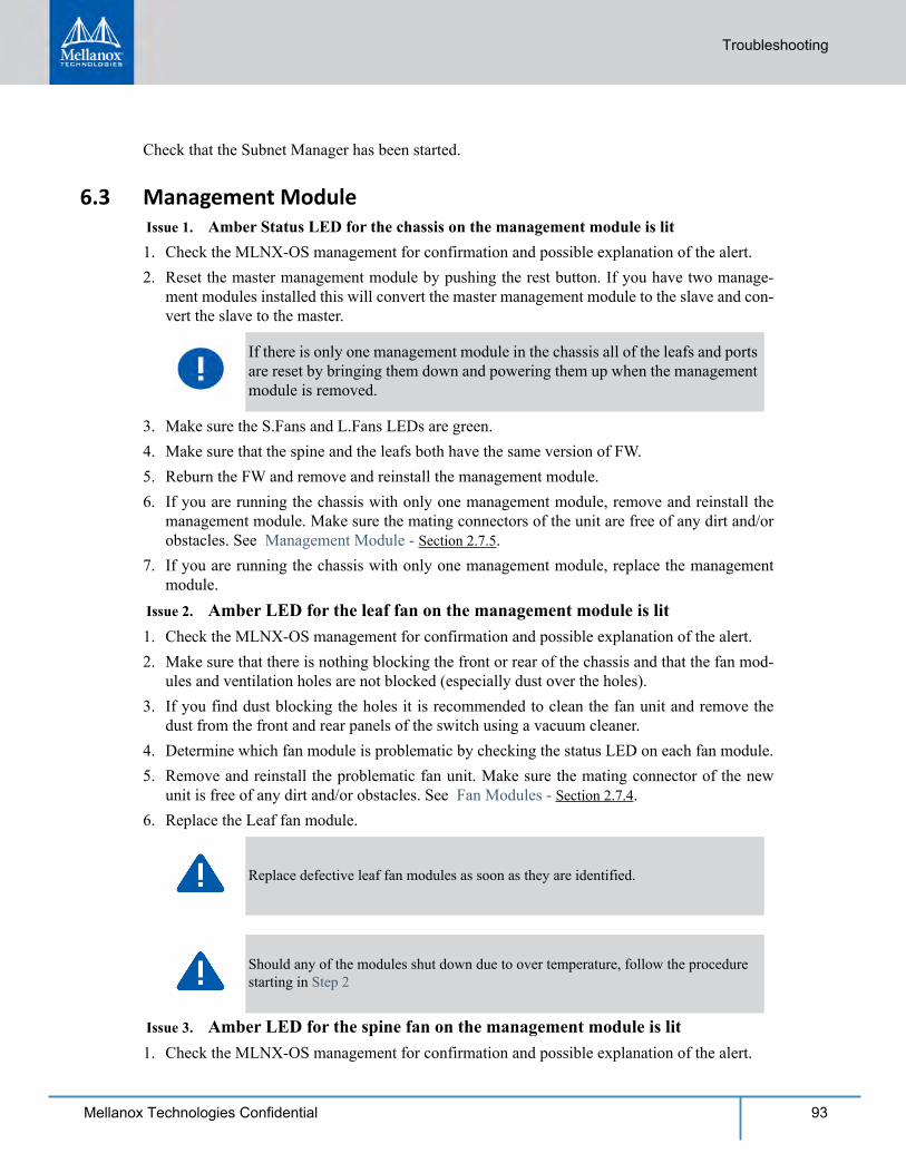
Troubleshooting
93Mellanox Technologies Confidential
Check that the Subnet Manager has been started.
6.3 Management Module Issue 1. Amber Status LED for the chassis on the management module is lit1. Check the MLNX-OS management for confirmation and possible explanation of the alert.2. Reset the master management module by pushing the rest button. If you have two manage-
ment modules installed this will convert the master management module to the slave and con-vert the slave to the master.
3. Make sure the S.Fans and L.Fans LEDs are green. 4. Make sure that the spine and the leafs both have the same version of FW. 5. Reburn the FW and remove and reinstall the management module.6. If you are running the chassis with only one management module, remove and reinstall the
management module. Make sure the mating connectors of the unit are free of any dirt and/or obstacles. See Management Module - Section 2.7.5.
7. If you are running the chassis with only one management module, replace the management module.
Issue 2. Amber LED for the leaf fan on the management module is lit1. Check the MLNX-OS management for confirmation and possible explanation of the alert.2. Make sure that there is nothing blocking the front or rear of the chassis and that the fan mod-
ules and ventilation holes are not blocked (especially dust over the holes).3. If you find dust blocking the holes it is recommended to clean the fan unit and remove the
dust from the front and rear panels of the switch using a vacuum cleaner.4. Determine which fan module is problematic by checking the status LED on each fan module.5. Remove and reinstall the problematic fan unit. Make sure the mating connector of the new
unit is free of any dirt and/or obstacles. See Fan Modules - Section 2.7.4.6. Replace the Leaf fan module.
Issue 3. Amber LED for the spine fan on the management module is lit1. Check the MLNX-OS management for confirmation and possible explanation of the alert.
If there is only one management module in the chassis all of the leafs and ports are reset by bringing them down and powering them up when the management module is removed.
Replace defective leaf fan modules as soon as they are identified.
Should any of the modules shut down due to over temperature, follow the procedure starting in Step 2
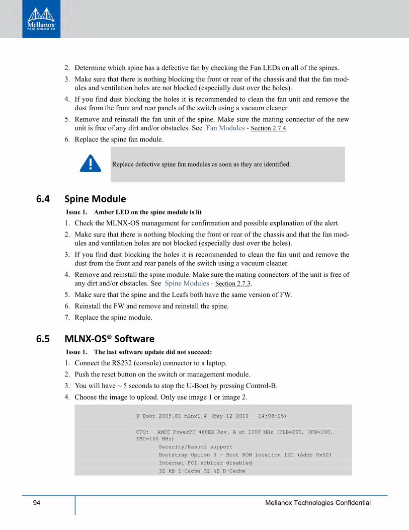
94 Mellanox Technologies Confidential
2. Determine which spine has a defective fan by checking the Fan LEDs on all of the spines. 3. Make sure that there is nothing blocking the front or rear of the chassis and that the fan mod-
ules and ventilation holes are not blocked (especially dust over the holes).4. If you find dust blocking the holes it is recommended to clean the fan unit and remove the
dust from the front and rear panels of the switch using a vacuum cleaner.5. Remove and reinstall the fan unit of the spine. Make sure the mating connector of the new
unit is free of any dirt and/or obstacles. See Fan Modules - Section 2.7.4.6. Replace the spine fan module.
6.4 Spine ModuleIssue 1. Amber LED on the spine module is lit
1. Check the MLNX-OS management for confirmation and possible explanation of the alert.2. Make sure that there is nothing blocking the front or rear of the chassis and that the fan mod-
ules and ventilation holes are not blocked (especially dust over the holes).3. If you find dust blocking the holes it is recommended to clean the fan unit and remove the
dust from the front and rear panels of the switch using a vacuum cleaner.4. Remove and reinstall the spine module. Make sure the mating connectors of the unit is free of
any dirt and/or obstacles. See Spine Modules - Section 2.7.3.5. Make sure that the spine and the Leafs both have the same version of FW. 6. Reinstall the FW and remove and reinstall the spine.7. Replace the spine module.
6.5 MLNX-OS® Software Issue 1. The last software update did not succeed:
1. Connect the RS232 (console) connector to a laptop.2. Push the reset button on the switch or management module.3. You will have ~ 5 seconds to stop the U-Boot by pressing Control-B.4. Choose the image to upload. Only use image 1 or image 2.
U-Boot 2009.01-mlnx1.4 (May 12 2010 - 14:08:15)
CPU: AMCC PowerPC 460EX Rev. A at 1000 MHz (PLB=200, OPB=100, EBC=100 MHz)
Security/Kasumi support
Bootstrap Option H - Boot ROM Location I2C (Addr 0x52)
Internal PCI arbiter disabled
32 kB I-Cache 32 kB D-Cache
Replace defective spine fan modules as soon as they are identified.
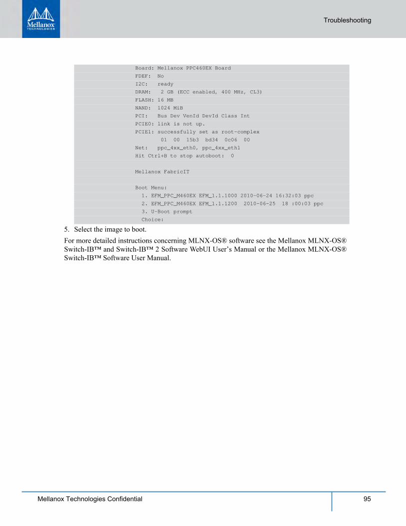
Board: Mellanox PPC460EX Board
FDEF: No
I2C: ready
DRAM: 2 GB (ECC enabled, 400 MHz, CL3)
FLASH: 16 MB
NAND: 1024 MiB
PCI: Bus Dev VenId DevId Class Int
PCIE0: link is not up.
PCIE1: successfully set as root-complex
01 00 15b3 bd34 0c06 00
Net: ppc_4xx_eth0, ppc_4xx_eth1
Hit Ctrl+B to stop autoboot: 0
Mellanox FabricIT
Boot Menu:
1. EFM_PPC_M460EX EFM_1.1.1000 2010-06-24 16:32:03 ppc
2. EFM_PPC_M460EX EFM_1.1.1200 2010-06-25 18 :00:03 ppc
3. U-Boot prompt
Choice:
Troubleshooting
95Mellanox Technologies Confidential
5. Select the image to boot.For more detailed instructions concerning MLNX-OS® software see the Mellanox MLNX-OS® Switch-IB™ and Switch-IB™ 2 Software WebUI User’s Manual or the Mellanox MLNX-OS® Switch-IB™ Software User Manual.
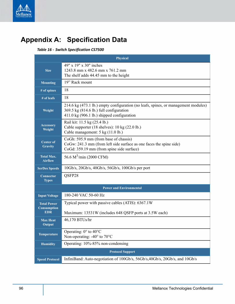
96 Mellanox Technologies Confidential
Appendix A: Specification Data Table 16 - Switch Specification CS7500
Physical
Size49" x 19" x 30" inches1243.8 mm x 482.6 mm x 761.2 mmThe shelf adds 44.45 mm to the height
Mounting 19” Rack mount
# of spines 18
# of leafs 18
Weight 214.6 kg (473.1 lb.) empty configuration (no leafs, spines, or management modules)369.5 kg (814.6 lb.) full configuration411.0 kg (906.1 lb.) shipped configuration
Accessory Weight
Rail kit: 11.5 kg (25.4 lb.)Cable supporter (18 shelves): 10 kg (22.0 lb.)Cable management: 5 kg (11.0 lb.)
Center of Gravity
CoGh: 595.9 mm (from base of chassis)CoGw: 241.3 mm (from left side surface as one faces the spine side)CoGd: 359.19 mm (from spine side surface)
Total Max. Airflow
56.6 M3/min (2000 CFM)
SerDes Speeds 10Gb/s, 20Gb/s, 40Gb/s, 56Gb/s, 100Gb/s per port
Connector Types
QSFP28
Power and Environmental
Input Voltage 180-240 VAC 50-60 Hz
Total Power Consumption
EDR
Typical power with passive cables (ATIS): 6367.1W
Maximum: 13531W (includes 648 QSFP ports at 3.5W each)
Max Heat Output
46,170 BTUs/hr
TemperatureOperating: 0° to 40°CNon-operating: -40° to 70°C
Humidity Operating: 10%-85% non-condensing
Protocol Support
Speed Protocol InfiniBand: Auto-negotiation of 100Gb/s, 56Gb/s,40Gb/s, 20Gb/s, and 10Gb/s
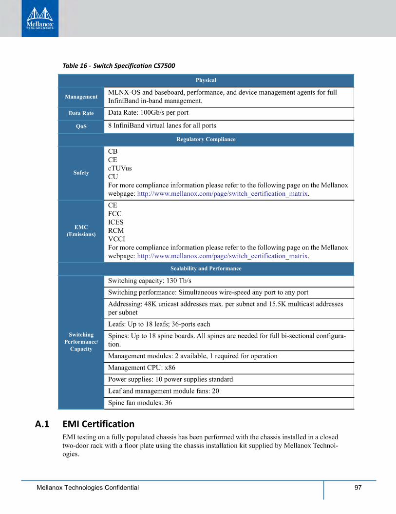
97Mellanox Technologies Confidential
A.1 EMI CertificationEMI testing on a fully populated chassis has been performed with the chassis installed in a closed two-door rack with a floor plate using the chassis installation kit supplied by Mellanox Technol-ogies.
ManagementMLNX-OS and baseboard, performance, and device management agents for full InfiniBand in-band management.
Data Rate Data Rate: 100Gb/s per port
QoS 8 InfiniBand virtual lanes for all ports
Regulatory Compliance
Safety
CBCEcTUVusCUFor more compliance information please refer to the following page on the Mellanox webpage: http://www.mellanox.com/page/switch_certification_matrix.
EMC (Emissions)
CEFCCICESRCMVCCIFor more compliance information please refer to the following page on the Mellanox webpage: http://www.mellanox.com/page/switch_certification_matrix.
Scalability and Performance
Switching Performance/
Capacity
Switching capacity: 130 Tb/sSwitching performance: Simultaneous wire-speed any port to any portAddressing: 48K unicast addresses max. per subnet and 15.5K multicast addresses per subnetLeafs: Up to 18 leafs; 36-ports eachSpines: Up to 18 spine boards. All spines are needed for full bi-sectional configura-tion.Management modules: 2 available, 1 required for operationManagement CPU: x86Power supplies: 10 power supplies standardLeaf and management module fans: 20Spine fan modules: 36
Table 16 - Switch Specification CS7500
Physical

98 Mellanox Technologies Confidential
A.2 Approved CablesFor a list of all approved cables please refer to: http://www.mellanox.com/page/cables?mtag=cable_overview
A.3 EMC CertificationsThe list of EMC certifications per chassis model type, for different markets in the world, is located on the Mellanox Website at:http://www.mellanox.com/page/environmental_compliance > Boards/Systems > Boards/Systems Certification Matrix

99Mellanox Technologies Confidential
Appendix B: Thermal Threshold DefinitionsThere are three thermal threshold definitions for Switch-IB™ and Switch-IB™ 2 switch device which impact the overall switch system operation state: Warning, Critical and Emergency.1. Warning – 100ºC
On managed systems only: When the Switch-IB™ or Switch-IB™ 2 device crosses the 100oC threshold, a Warning Threshold message will be issued by the MLNX-OS® management SW, indicating to system administration that the switch has crossed the Warning threshold.Note that this temperature threshold does not require nor lead to any action by hardware (such as switch shutdown).
2. Critical – 120ºCWhen the Switch-IB™ or Switch-IB™ 2 device crosses this temperature, the firmware will automatically shut down the device.
3. Emergency – 130ºCIn case the firmware fails to shut down the Switch-IB™ or Switch-IB™ 2 device upon crossing the Critical threshold, the Switch-IB™ or Switch-IB™ 2 device will auto-shutdown upon crossing the Emergency (130ºC) threshold.
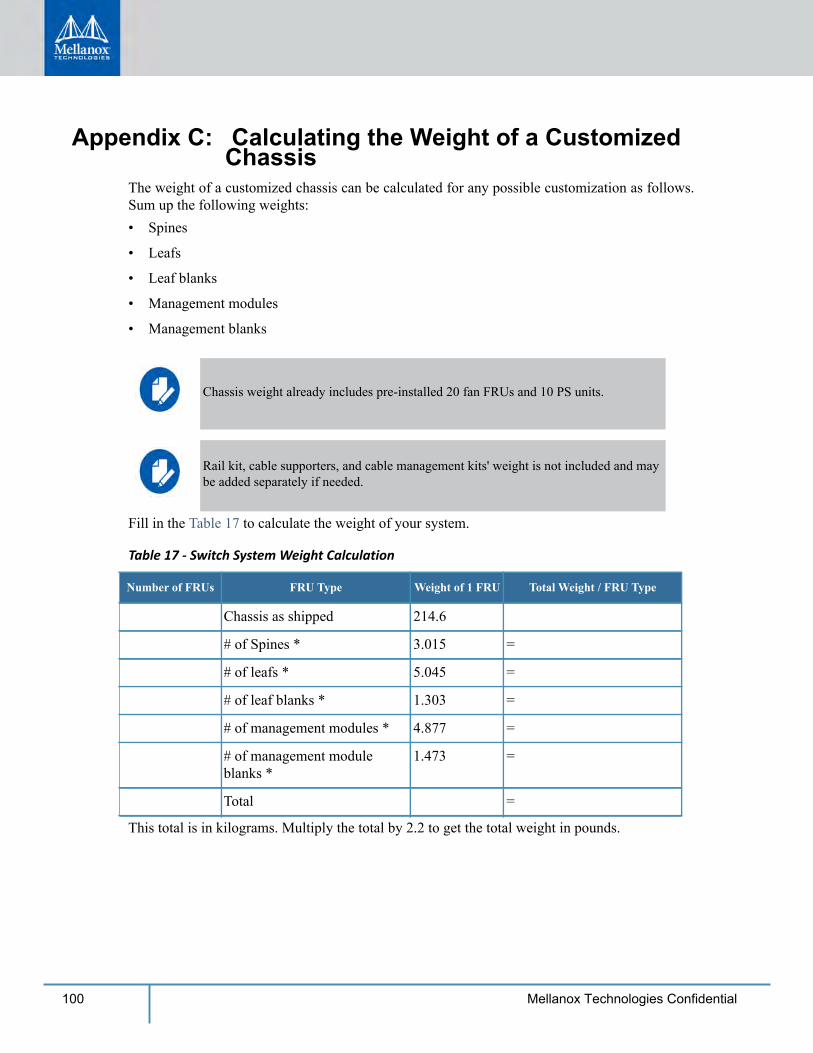
100 Mellanox Technologies Confidential
Appendix C: Calculating the Weight of a Customized Chassis
The weight of a customized chassis can be calculated for any possible customization as follows. Sum up the following weights:• Spines
• Leafs
• Leaf blanks
• Management modules
• Management blanks
Fill in the Table 17 to calculate the weight of your system.
Table 17 - Switch System Weight Calculation
Number of FRUs FRU Type Weight of 1 FRU Total Weight / FRU Type
Chassis as shipped 214.6
# of Spines * 3.015 =
# of leafs * 5.045 =
# of leaf blanks * 1.303 =
# of management modules * 4.877 =
# of management module blanks *
1.473 =
Total =
This total is in kilograms. Multiply the total by 2.2 to get the total weight in pounds.
Chassis weight already includes pre-installed 20 fan FRUs and 10 PS units.
Rail kit, cable supporters, and cable management kits' weight is not included and may be added separately if needed.
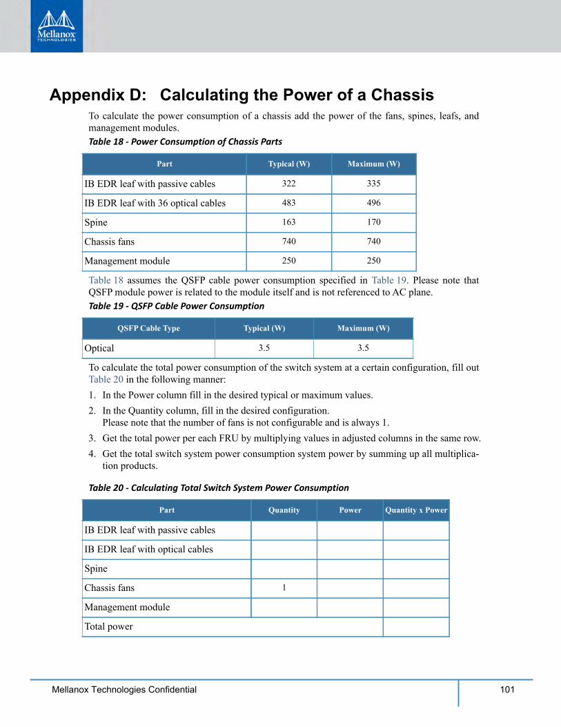
101Mellanox Technologies Confidential
Appendix D: Calculating the Power of a ChassisTo calculate the power consumption of a chassis add the power of the fans, spines, leafs, and management modules.Table 18 - Power Consumption of Chassis Parts
Part Typical (W) Maximum (W)
IB EDR leaf with passive cables 322 335
IB EDR leaf with 36 optical cables 483 496
Spine 163 170
Chassis fans 740 740
Management module 250 250
Table 18 assumes the QSFP cable power consumption specified in Table 19. Please note that QSFP module power is related to the module itself and is not referenced to AC plane.Table 19 - QSFP Cable Power Consumption
QSFP Cable Type Typical (W) Maximum (W)
Optical 3.5 3.5
To calculate the total power consumption of the switch system at a certain configuration, fill out Table 20 in the following manner:1. In the Power column fill in the desired typical or maximum values.2. In the Quantity column, fill in the desired configuration.
Please note that the number of fans is not configurable and is always 1.3. Get the total power per each FRU by multiplying values in adjusted columns in the same row.4. Get the total switch system power consumption system power by summing up all multiplica-
tion products.
Table 20 - Calculating Total Switch System Power Consumption
Part Quantity Power Quantity x Power
IB EDR leaf with passive cables
IB EDR leaf with optical cables
Spine
Chassis fans 1
Management module
Total power
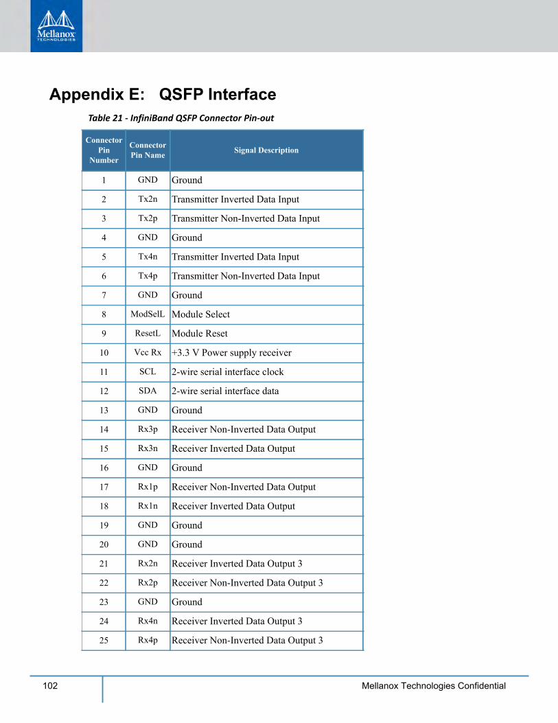
102 Mellanox Technologies Confidential
Appendix E: QSFP InterfaceTable 21 - InfiniBand QSFP Connector Pin-out
Connector Pin
Number
Connector Pin Name Signal Description
1 GND Ground
2 Tx2n Transmitter Inverted Data Input
3 Tx2p Transmitter Non-Inverted Data Input
4 GND Ground
5 Tx4n Transmitter Inverted Data Input
6 Tx4p Transmitter Non-Inverted Data Input
7 GND Ground
8 ModSelL Module Select
9 ResetL Module Reset
10 Vcc Rx +3.3 V Power supply receiver
11 SCL 2-wire serial interface clock
12 SDA 2-wire serial interface data
13 GND Ground
14 Rx3p Receiver Non-Inverted Data Output
15 Rx3n Receiver Inverted Data Output
16 GND Ground
17 Rx1p Receiver Non-Inverted Data Output
18 Rx1n Receiver Inverted Data Output
19 GND Ground
20 GND Ground
21 Rx2n Receiver Inverted Data Output 3
22 Rx2p Receiver Non-Inverted Data Output 3
23 GND Ground
24 Rx4n Receiver Inverted Data Output 3
25 Rx4p Receiver Non-Inverted Data Output 3
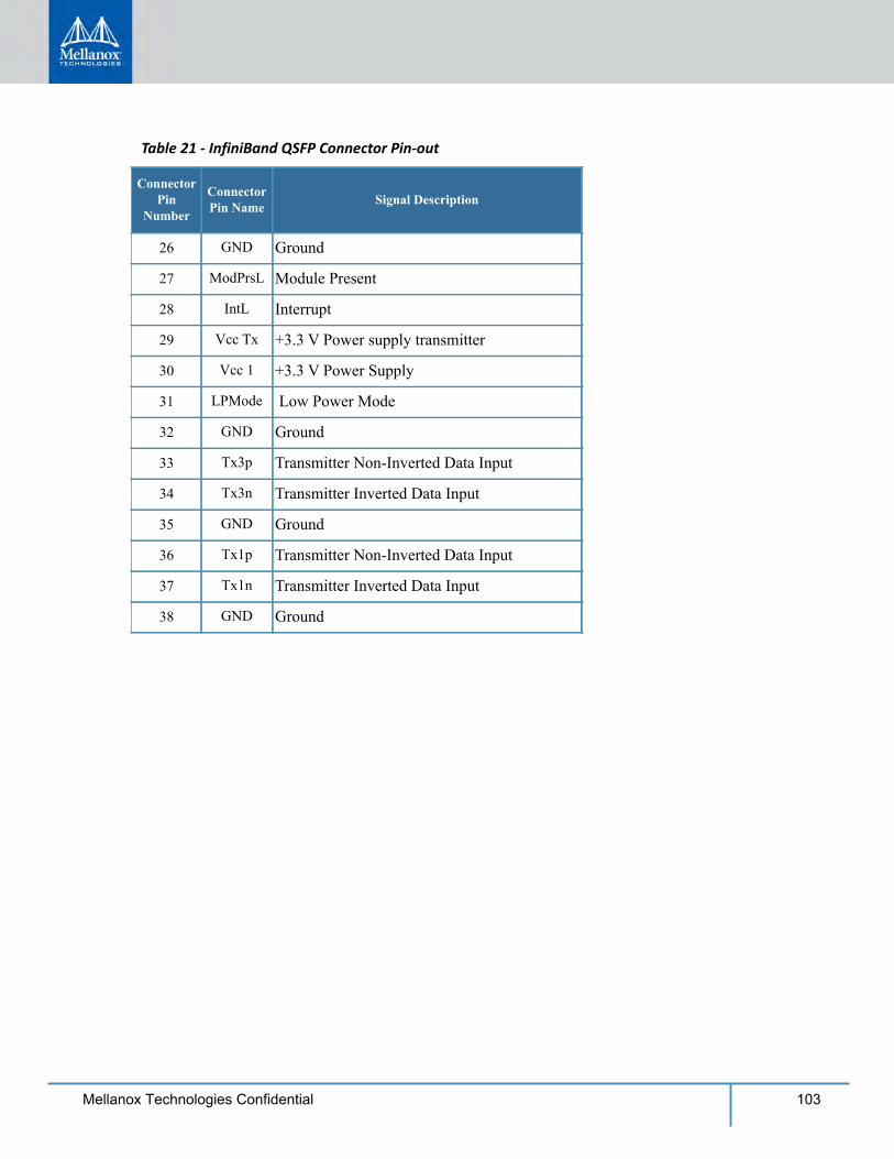
103Mellanox Technologies Confidential
26 GND Ground
27 ModPrsL Module Present
28 IntL Interrupt
29 Vcc Tx +3.3 V Power supply transmitter
30 Vcc 1 +3.3 V Power Supply
31 LPMode Low Power Mode
32 GND Ground
33 Tx3p Transmitter Non-Inverted Data Input
34 Tx3n Transmitter Inverted Data Input
35 GND Ground
36 Tx1p Transmitter Non-Inverted Data Input
37 Tx1n Transmitter Inverted Data Input
38 GND Ground
Table 21 - InfiniBand QSFP Connector Pin-out
Connector Pin
Number
Connector Pin Name Signal Description
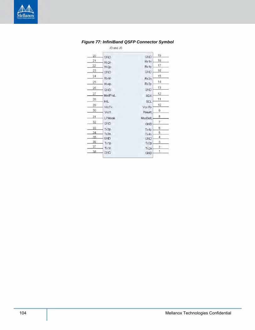
104 Mellanox Technologies Confidential
Figure 77: InfiniBand QSFP Connector Symbol
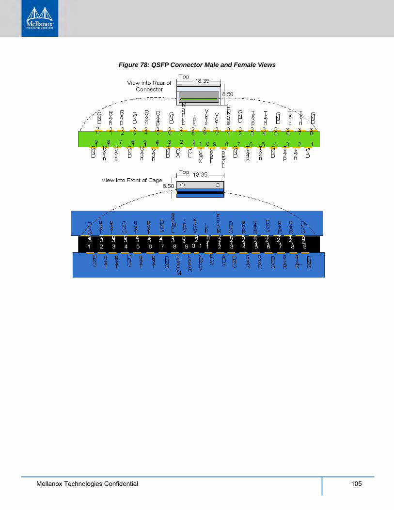
105Mellanox Technologies Confidential
Figure 78: QSFP Connector Male and Female Views
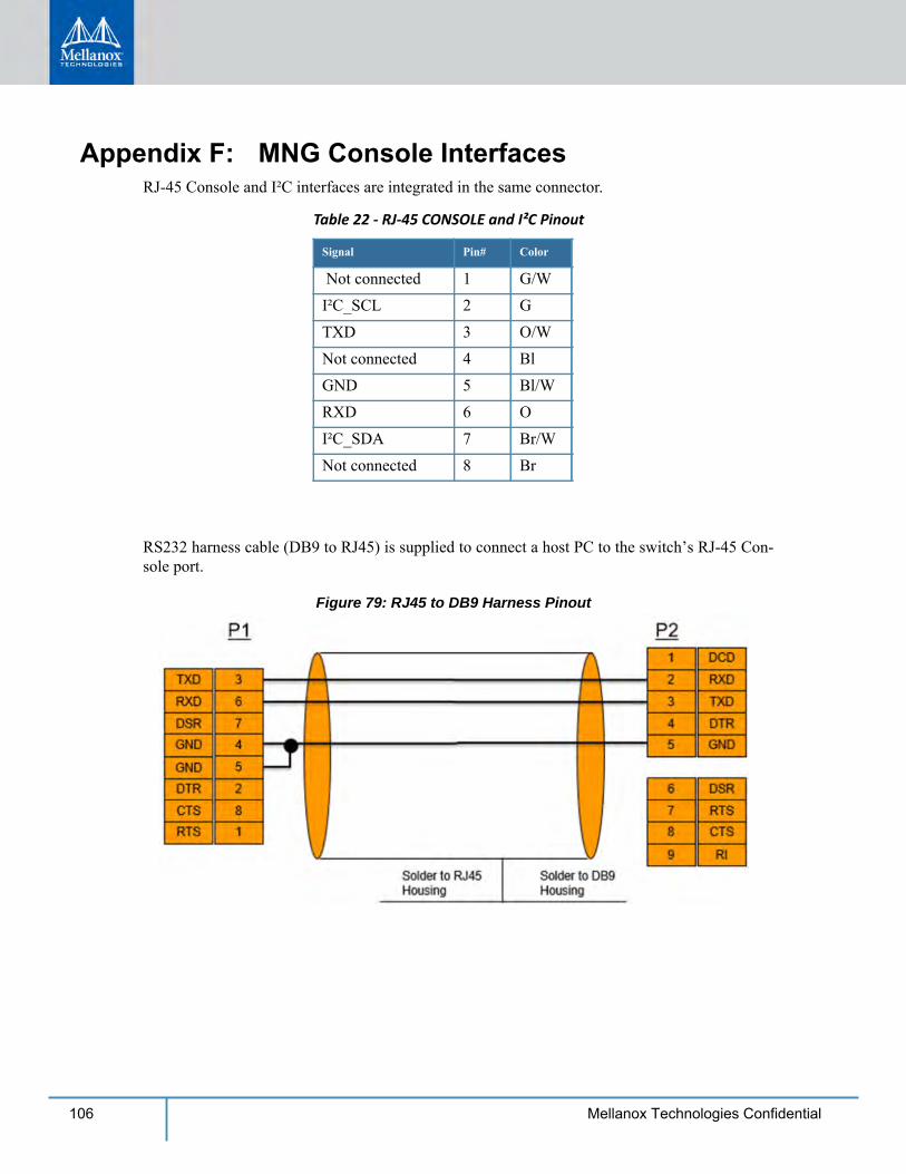
106 Mellanox Technologies Confidential
Appendix F: MNG Console InterfacesRJ-45 Console and I²C interfaces are integrated in the same connector.
Table 22 - RJ-45 CONSOLE and I²C Pinout
Signal Pin# Color
Not connected 1 G/WI²C_SCL 2 GTXD 3 O/WNot connected 4 BlGND 5 Bl/WRXD 6 OI²C_SDA 7 Br/WNot connected 8 Br
RS232 harness cable (DB9 to RJ45) is supplied to connect a host PC to the switch’s RJ-45 Con-sole port.
Figure 79: RJ45 to DB9 Harness Pinout
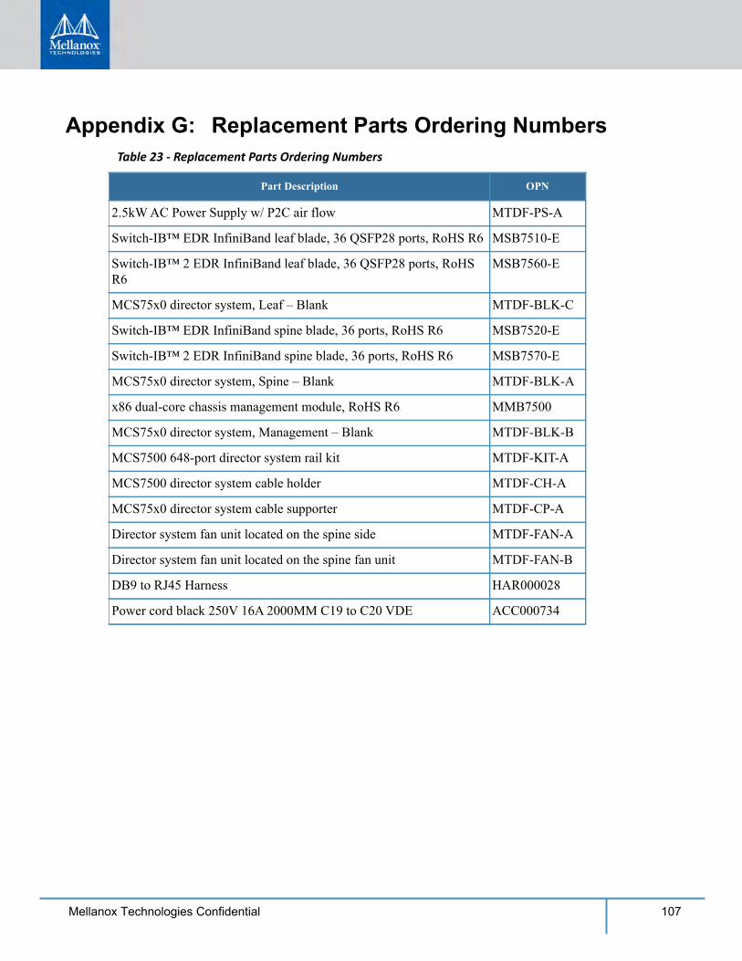
107Mellanox Technologies Confidential
Appendix G: Replacement Parts Ordering NumbersTable 23 - Replacement Parts Ordering Numbers
Part Description OPN
2.5kW AC Power Supply w/ P2C air flow MTDF-PS-A
Switch-IB™ EDR InfiniBand leaf blade, 36 QSFP28 ports, RoHS R6 MSB7510-E
Switch-IB™ 2 EDR InfiniBand leaf blade, 36 QSFP28 ports, RoHS R6
MSB7560-E
MCS75x0 director system, Leaf – Blank MTDF-BLK-C
Switch-IB™ EDR InfiniBand spine blade, 36 ports, RoHS R6 MSB7520-E
Switch-IB™ 2 EDR InfiniBand spine blade, 36 ports, RoHS R6 MSB7570-E
MCS75x0 director system, Spine – Blank MTDF-BLK-A
x86 dual-core chassis management module, RoHS R6 MMB7500
MCS75x0 director system, Management – Blank MTDF-BLK-B
MCS7500 648-port director system rail kit MTDF-KIT-A
MCS7500 director system cable holder MTDF-CH-A
MCS75x0 director system cable supporter MTDF-CP-A
Director system fan unit located on the spine side MTDF-FAN-A
Director system fan unit located on the spine fan unit MTDF-FAN-B
DB9 to RJ45 Harness HAR000028
Power cord black 250V 16A 2000MM C19 to C20 VDE ACC000734

108 Mellanox Technologies Confidential
Appendix H: Safety Warnings (Multiple Languages)H.1 Nordic Countries Notices
H.2 Installation Safety Warnings (English)1. Installation Instructions
2. Bodily Injury Due to Weight
3. Heavy Equipment
4. Risk of Electric Shock!
5. Over-temperature
6. Stacking the Chassis
Finland: “Laite on liitettävä suojakoskettimilla varustettuun pistorasiaan”Norway: “Apparatet må tilkoples jordet stikkontakt”Sweden: “Apparaten skall anslutas till jordat uttag”
Read all installation instructions before connecting the equipment to the power source.
Use enough people to safely lift this product.
This equipment is heavy and should be moved using a mechanical lift to avoid injuries.
Risk of Electric Shock!With the fan module removed power pins are accessible within the module cavity. DO NOT insert tools or body parts into the fan module cavity.
This equipment should not be operated in an area with an ambient temperature exceed-ing the maximum recommended: 45°C (113°F). Moreover, to guarantee proper , allow at least 8cm (3 inches) of clearance around the ventilation openings.
The chassis should not be stacked on any other equipment. If the chassis falls, it can cause bodily injury and equipment damage.
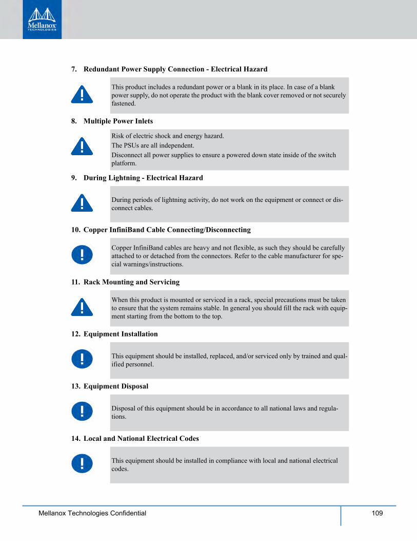
109Mellanox Technologies Confidential
7. Redundant Power Supply Connection - Electrical Hazard
8. Multiple Power Inlets
9. During Lightning - Electrical Hazard
10. Copper InfiniBand Cable Connecting/Disconnecting
11. Rack Mounting and Servicing
12. Equipment Installation
13. Equipment Disposal
14. Local and National Electrical Codes
This product includes a redundant power or a blank in its place. In case of a blank power supply, do not operate the product with the blank cover removed or not securely fastened.
Risk of electric shock and energy hazard.The PSUs are all independent.Disconnect all power supplies to ensure a powered down state inside of the switch platform.
During periods of lightning activity, do not work on the equipment or connect or dis-connect cables.
Copper InfiniBand cables are heavy and not flexible, as such they should be carefully attached to or detached from the connectors. Refer to the cable manufacturer for spe-cial warnings/instructions.
When this product is mounted or serviced in a rack, special precautions must be taken to ensure that the system remains stable. In general you should fill the rack with equip-ment starting from the bottom to the top.
This equipment should be installed, replaced, and/or serviced only by trained and qual-ified personnel.
Disposal of this equipment should be in accordance to all national laws and regula-tions.
This equipment should be installed in compliance with local and national electrical codes.

110 Mellanox Technologies Confidential
15. UL Listed and CSA Certified Power Supply Cord
16. Installation codes
17. Interconnection Of Units
18. Overcurrent Protection
19. Do Not Use the Switch as a Shelf or Work Space
20. WEEE Directive
For North American power connection, select a power supply cord that is UL Listed and CSA Certified, 3 - conductor, [16 AWG], terminated with a molded plug rated at 125 V, [13 A], with a minimum length of 1.5m [six feet] but no longer than 4.5m.For European connection, select a power supply cord that is internationally harmonized and marked “<HAR>”, 3 - conductor, minimum 1.0 mm2 wire, rated at 300 V, with a PVC insulated jacket. The cord must have a molded plug rated at 250 V, 10 A.
This device must be installed according to the latest version of the country national electrical codes. For North America, equipment must be installed in accordance to the applicable requirements in the US National Electrical Code and the Canadian Electri-cal Code.
Cables for connecting to the unit RS232 and Ethernet Interfaces must be UL certified type DP-1 or DP-2. (Note- when residing in non LPS circuit)
A readily accessible Listed branch circuit overcurrent protective device rated 20 A must be incorporated in the building wiring.
Caution: Slide/rail mounted equipment is not to be used as a shelf or a work space. The rails are not intended for sliding the unit away from the rack. It is for permanent instal-lation at final resting place only, not used for service and maintenance
According to the WEEE Directive 2002/96/EC, all waste electrical and electronic equipment (EEE) should be collected separately and not disposed of with regular household waste.Dispose of this product and all of its parts in a responsible and environmentally friendly way.
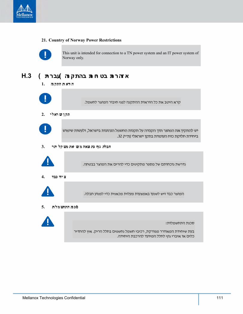
111Mellanox Technologies Confidential
21. Country of Norway Power Restrictions
H.3 ( תירבע) הנקתהב תוחיטב תורהזא1. הנקתה תוארוה
2. ילארשי ןקת
3. רתי לקשמ תאישנמ האצותכ ףוג תלבח
4. דבכ דויצ
5. תולמשחתה תנכס !
This unit is intended for connection to a TN power system and an IT power system of Norway only.
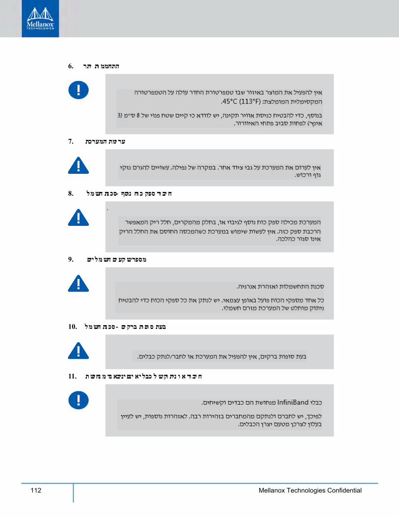
112 Mellanox Technologies Confidential
6. רתי תוממחתה
7. תכרעמה תמירע
8. למשח תנכס- ףסונ חוכ קפס רוביח
9. םיילמשח םיעקש רפסמ
10. למשח תנכס - םיקרב תופוס תעב
11. תשוחנמ דנאביניפניא ילבכ לש קותינ וא רוביח
.
113Mellanox Technologies Confidential
12. ןוראב ףדמ יבג לע הבכרה
13. רצומה תנקתה
14. תלוספ תכלשה
15. תוימואלו תוימוקמ למשח תונקת
16. למשח תקפסא לבכ
17. הנקתה תונקת
114 Mellanox Technologies Confidential
18. תוכרעמ ןיב רוביח
19. הובג חתמ ינפמ הנגה
20. הדובע חטש וא ףדמכ תכרעמב שמתשהל ןיא
21. WEEE תנקת
22. היגברונב תוילמשח תולבגמ
H.4 (Chinese)1.
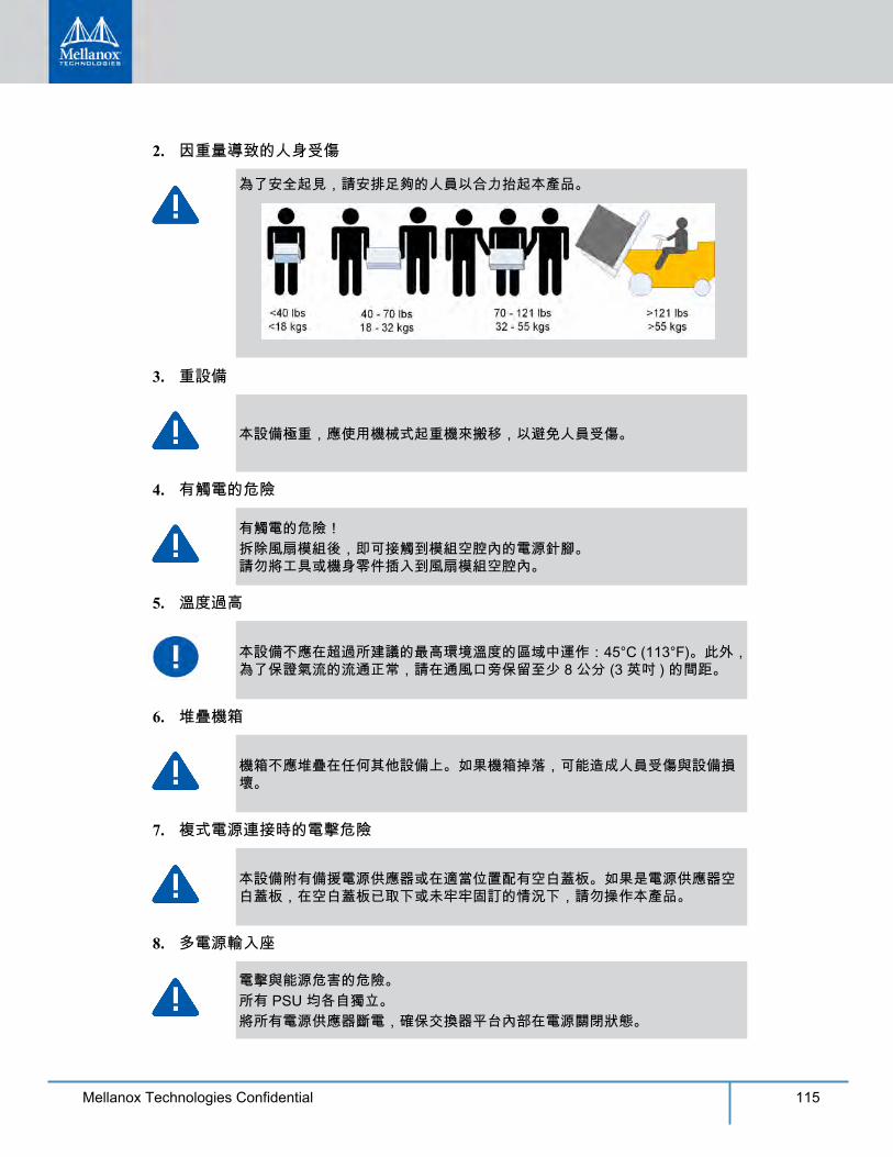
115Mellanox Technologies Confidential
2.
3.
4.
5.
6.
7.
8.
116 Mellanox Technologies Confidential
9.
10. InfiniBand
11.
12.
13.
14.
15. UL CSA
16.
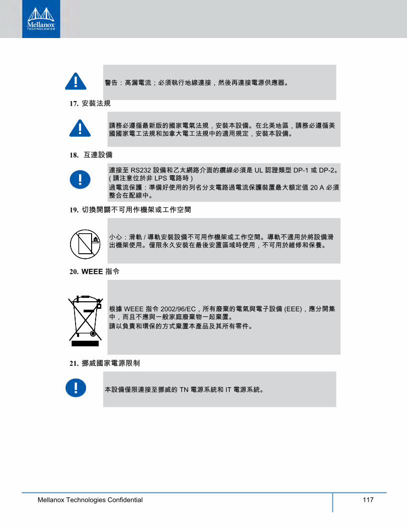
117Mellanox Technologies Confidential
17.
18.
19.
20. WEEE
21.
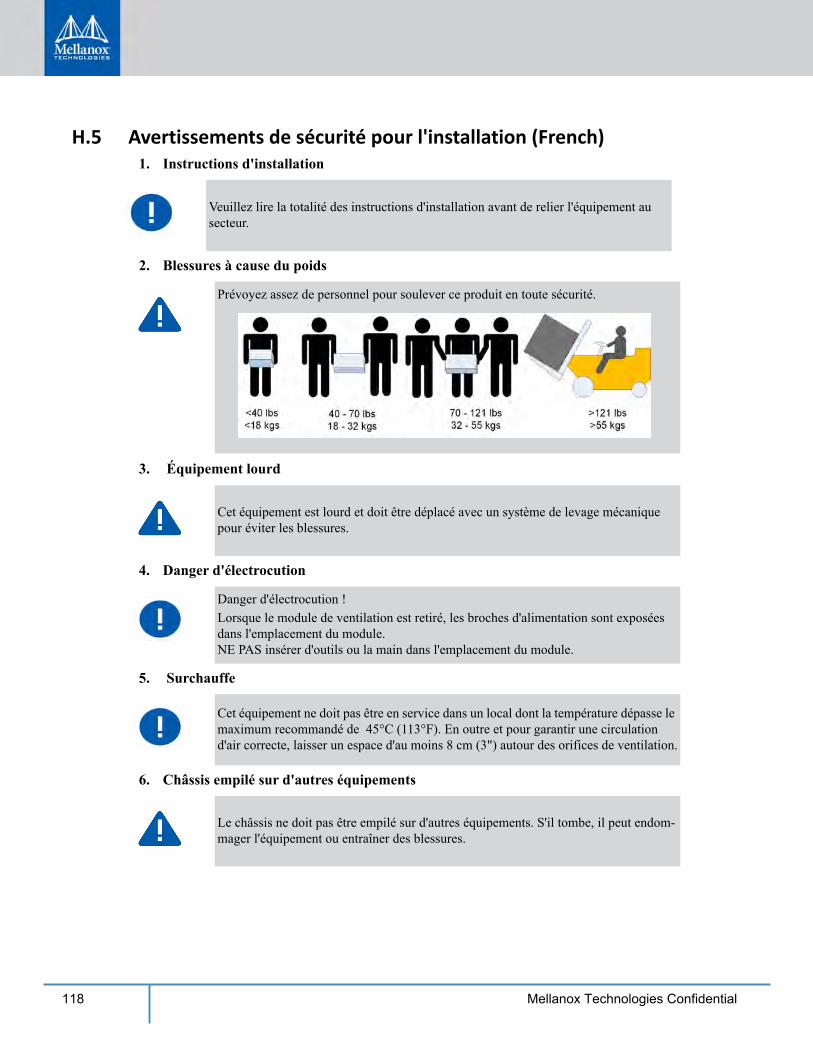
118 Mellanox Technologies Confidential
H.5 Avertissements de sécurité pour l'installation (French)1. Instructions d'installation
2. Blessures à cause du poids
3. Équipement lourd
4. Danger d'électrocution
5. Surchauffe
6. Châssis empilé sur d'autres équipements
Veuillez lire la totalité des instructions d'installation avant de relier l'équipement au secteur.
Prévoyez assez de personnel pour soulever ce produit en toute sécurité.
Cet équipement est lourd et doit être déplacé avec un système de levage mécanique pour éviter les blessures.
Danger d'électrocution !Lorsque le module de ventilation est retiré, les broches d'alimentation sont exposées dans l'emplacement du module. NE PAS insérer d'outils ou la main dans l'emplacement du module.
Cet équipement ne doit pas être en service dans un local dont la température dépasse le maximum recommandé de 45°C (113°F). En outre et pour garantir une circulation d'air correcte, laisser un espace d'au moins 8 cm (3") autour des orifices de ventilation.
Le châssis ne doit pas être empilé sur d'autres équipements. S'il tombe, il peut endom-mager l'équipement ou entraîner des blessures.
119Mellanox Technologies Confidential
7. Connexion de l'alimentation redondante : danger d'électrocution
8. Plusieurs prises d'alimentation
9. En cas d'orage, danger d'électrocution
10. Connexion et déconnexion du câble InfiniBand en cuivre
11. Montage en rack et maintenance
12. Installation de l'équipement
13. Mise au rebut de l'équipement
14. Codes électriques locaux et nationaux
Ce produit est équipé d'une alimentation redondante ou d'un cache si elle est absente. Dans ce dernier cas, ne pas faire fonctionner le produit si le cache est retiré ou mal fixé.
Risque et danger d'électrocution.Les alimentations sont toutes indépendantes.Pour s'assurer que le commutateur est bien hors tension, débranchez toutes les alimen-tations.
Pendant un orage, ne pas travailler sur l'équipement ni brancher ou débrancher des câbles.
Les câbles InfiniBand en cuivre sont lourds et peu flexibles. Par conséquent, il faut procéder avec soin pour les brancher ou les débrancher des connecteurs. Consulter le fabricant du câble pour obtenir des instructions ou des avertissements spécifiques.
Lors du montage ou de la maintenance de ce produit dans un rack, il faut faire spéciale-ment attention pour s'assurer que l'ensemble reste stable. En règle générale, le rack doit être rempli en commençant par le bas.
Cet équipement ne doit être installé, remplacé et maintenu que par un personnel formé et qualifié.
La mise au rebut de cet équipement doit se faire conformément à toutes les lois et réglementations nationales.
Cet équipement doit être installé conformément aux codes électriques locaux et nation-aux.
120 Mellanox Technologies Confidential
15. Codes d'installation
16. Cordon d'alimentation UL Listed et certifié CSA
17. Courant de fuite élevé
18. Interconnexion des unités
19. Ne pas utiliser comme étagère ou plan de travail
20. Directive DEEE
Cet appareil doit être installé conformément à la version la plus récente des codes élec-trique nationaux. En Amérique du Nord, l'équipement doit être installé en respectant les exigences de l'US National Electrical Code et du Code canadien de l'électricité.
Pour le branchement électrique en Amérique du Nord, utiliser un cordon d'alimenta-tion UL Listed et CSA Certified, à 3 conducteurs [calibre 16 AWG], avec une prise moulée 125 V [13 A], faisant au moins 1,5 m de long [six pieds] et au plus 4,5 m.Pour le branchement électrique en Europe, utiliser un cordon d'alimentation au format international harmonisé (marqué <HAR>), à 3 conducteurs d'au moins 1 mm2 de sec-tion, 300 V, avec une gaine isolante en PVC. Le cordon doit avoir une prise moulée 250 V 10 A.
Avertissement : courant de fuite élevé, une connexion à la terre est indispensable avant de brancher l'alimentation.
Les câbles de connexion aux interfaces RS232 et Ethernet de l'appareil doivent être certifié UL de type DP-1 ou DP-2. (Note : en cas d'installation sur un circuit dont la puissance n'est pas limitée)Protection contre les surintensités : le câblage de l'immeuble doit intégrer un dispositif certifié de protection contre les surintensités, calibré à 20 A et aisément accessible.
Attention : un équipement coulissant ou monté sur rail ne doit pas servir d'étagère ni de plan de travail. Les rails ne sont pas destinés à faire coulisser l'unité hors du rack. Ils sont destinés à une installation permanente à l'emplacement final, pas pour l'entretien ni la maintenance.
Selon la Directive 2002/96/CE (DEEE), tous les déchets d'équipements électriques et électroniques (EEE) doivent être collectés séparément et ne pas être mis au rebut avec les déchets ménagers habituels.Ce produit et toutes ses pièces doivent être mis au rebut d'une manière responsable, respectant l'environnement.
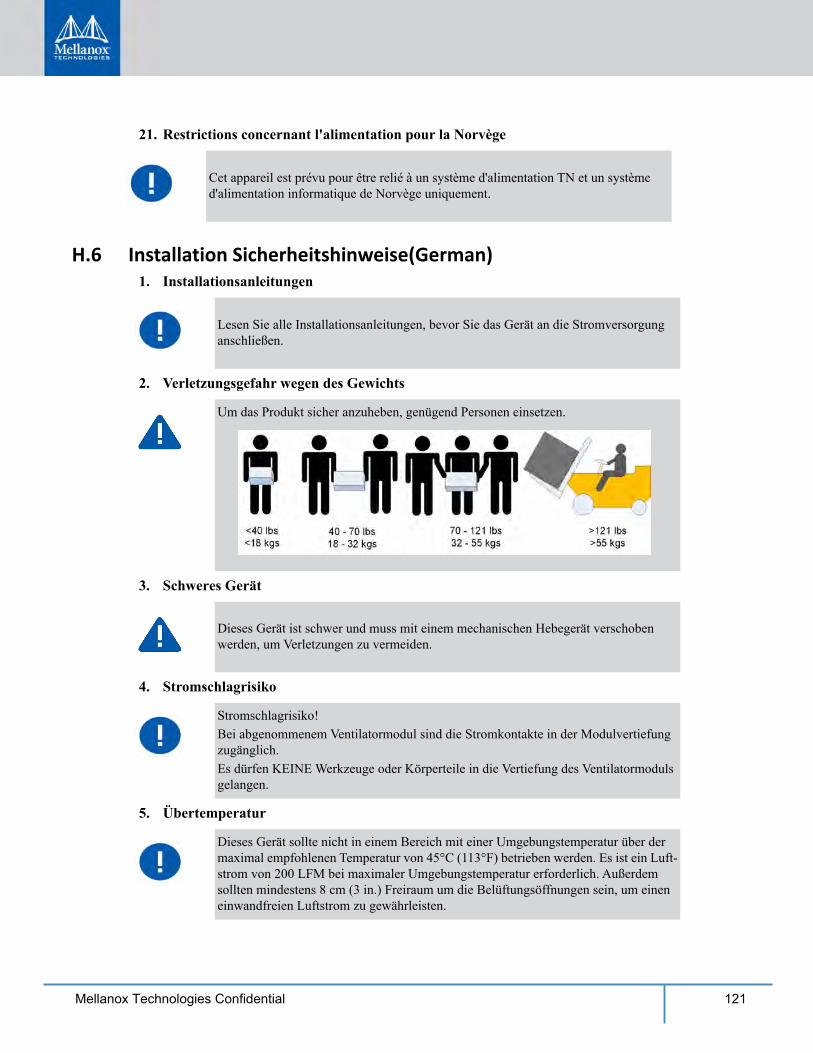
121Mellanox Technologies Confidential
21. Restrictions concernant l'alimentation pour la Norvège
H.6 Installation Sicherheitshinweise(German)1. Installationsanleitungen
2. Verletzungsgefahr wegen des Gewichts
3. Schweres Gerät
4. Stromschlagrisiko
5. Übertemperatur
Cet appareil est prévu pour être relié à un système d'alimentation TN et un système d'alimentation informatique de Norvège uniquement.
Lesen Sie alle Installationsanleitungen, bevor Sie das Gerät an die Stromversorgung anschließen.
Um das Produkt sicher anzuheben, genügend Personen einsetzen.
Dieses Gerät ist schwer und muss mit einem mechanischen Hebegerät verschoben werden, um Verletzungen zu vermeiden.
Stromschlagrisiko!Bei abgenommenem Ventilatormodul sind die Stromkontakte in der Modulvertiefung zugänglich. Es dürfen KEINE Werkzeuge oder Körperteile in die Vertiefung des Ventilatormoduls gelangen.
Dieses Gerät sollte nicht in einem Bereich mit einer Umgebungstemperatur über der maximal empfohlenen Temperatur von 45°C (113°F) betrieben werden. Es ist ein Luft-strom von 200 LFM bei maximaler Umgebungstemperatur erforderlich. Außerdem sollten mindestens 8 cm (3 in.) Freiraum um die Belüftungsöffnungen sein, um einen einwandfreien Luftstrom zu gewährleisten.
122 Mellanox Technologies Confidential
6. Stapeln des Chassis
7. Mehrere Stromeingänge
8. Bei Gewitter - Elektrische Gefahr
9. Anschließen/Trennen von InfiniBand-Kupferkabel
10. Rack-Montage und Wartung
11. Geräteinstallation
12. Geräteentsorgung
13. Regionale und nationale elektrische Bestimmungen
Das Chassis sollte nicht auf andere Geräte gestapelt werden. Wenn das Chassis herunt-erfällt, kann es zu Verletzungen und Beschädigungen an Geräten führen.
Risiko eines Stromschlags und Stomgefahr.Alle Stromversorgungseinheiten sind unabhängig.Trennen Sie alle Stomversorgungen, um einen abgeschalteten Zustand im Inneren der Switch-Plattform sicherzustellen.
Arbeiten Sie während eines Gewitters und Blitzschlag nicht am Gerät, schließen Sie keine Kabel an oder ab.
InfiniBand-Kupferkabel sind schwer und nicht flexible. Deshalb müssen sie vorsichtig an die Anschlüsse angebracht bzw. davon getrennt werden. Lesen Sie die speziellen Warnungen und Anleitungen des Kabelherstellers.
Wenn dieses Produkt in einem Rack montiert oder gewartet wird, sind besondere Vor-sichtsmaßnahmen zu ergreifen, um die Stabilität des Systems zu gewährleisten. Im Allgemeinen sollten Sie das Gestell von unten nach oben mit Geräten füllen.
Diese Gerät sollte nur von geschultem und qualifiziertem Personal installiert, aus-getauscht oder gewartet werden.
Die Entsorgung dieses Geräts sollte unter Beachtung aller nationalen Gesetze Bestim-mungen erfolgen.
Dieses Gerät sollte unter Beachtung der regionalen und nationalen elektrischen Bes-timmungen installiert werden.
123Mellanox Technologies Confidential
14. Installationscodes
15. UL- und CSA-zertifiziertes Netzkabel
16. Hoher Ableitstrom
17. Installationscodes
18. Verbindung der Geräte untereinander
19. Switch nicht als Regal oder Arbeitsplatz nutzen
Dieses Gerät muss entsprechend der aktuellsten Version des National Electrical Code installiert weden. In Nodamerika muss das Gerät gemäß den geltenden Anforderungen des US National Electrical Code und des Canadian Electrical Code installiert werden.
Für Nordamerika Stromanschluss, wählen Sie ein Netzkabel, das UL-und CSA Certi-fied 3 - Leiter, [18 AWG], mit einem angespritztem Stecker bewertet bei 125 V, [15], mit einer Mindestlänge von 1,5 m [Six Feet] aber nicht mehr als 4,5 m.Für die europäischen Zusammenhang, wählen Sie ein Netzkabel, das international harmonisiert und der Aufschrift "<HAR>", 3 - Leiter, mindestens 0,75 mm2 Draht, bewertet mit 300 V, mit einem PVC-Mantel isoliert. Das Kabel muss eine angespritztem Stecker bewertet bei 250 V, 10 A. "
WARNUNG: Hohe Ableitstrom; Earth Verbindung, bevor Sie die Verbindung von wesentlicher Bedeutung werden.
Dieses Gerät muss installiert sein, entsprechend auf die neueste Version des Landes National Electrical Code. Für Nordamerika, müssen in Übereinstimmung mit den gel-tenden Vorschriften in der US-amerikanischen National Electrical Code und dem Canadian Electrical Code.
Kabel für den Anschluss an das Gerät RS232-und Ethernet-Schnittstellen müssen UL zertifiziert Typ DP-1 oder DP-2. (Hinweis-, wenn nicht mit Wohnsitz in LPS-Schal-tung)
Überstromschutz: Eine leicht zugängliche Auflistung Abzweigleitung Überstrom-Schutzeinrichtung 20 A bewertet werden müssen in dem Gebäude Verkabelung.
Achtung: Auf Schieber/Schienen montiertes Gerät ist nicht als Regal oder Arbeitsbere-ich zu nutzen. Die Schienen sind nicht dafür bestimmt, die Einheit aus dem Gestell weg zu ziehen. Sie sind nur für die permanente Installation an einem endgültigen Stan-dort gedacht, nicht für Instandhaltung und Wartung.
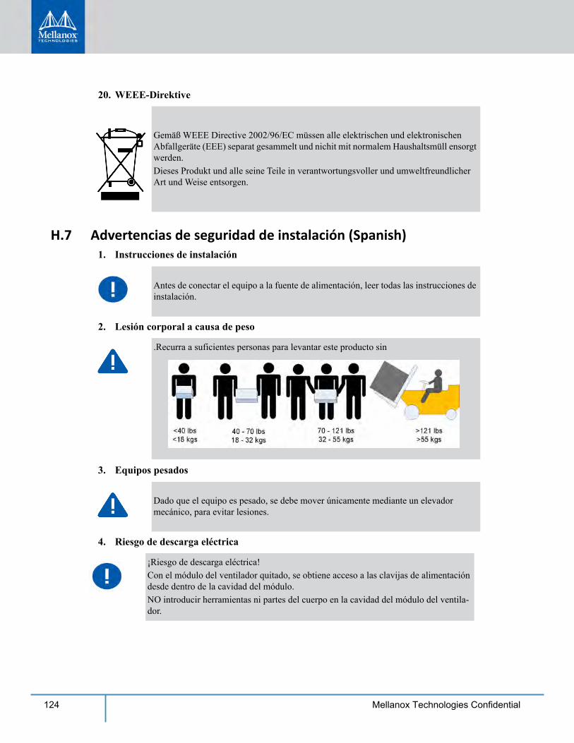
124 Mellanox Technologies Confidential
20. WEEE-Direktive
H.7 Advertencias de seguridad de instalación (Spanish) 1. Instrucciones de instalación
2. Lesión corporal a causa de peso
3. Equipos pesados
4. Riesgo de descarga eléctrica
Gemäß WEEE Directive 2002/96/EC müssen alle elektrischen und elektronischen Abfallgeräte (EEE) separat gesammelt und nichit mit normalem Haushaltsmüll ensorgt werden.Dieses Produkt und alle seine Teile in verantwortungsvoller und umweltfreundlicher Art und Weise entsorgen.
Antes de conectar el equipo a la fuente de alimentación, leer todas las instrucciones de instalación.
.Recurra a suficientes personas para levantar este producto sin
Dado que el equipo es pesado, se debe mover únicamente mediante un elevador mecánico, para evitar lesiones.
¡Riesgo de descarga eléctrica!Con el módulo del ventilador quitado, se obtiene acceso a las clavijas de alimentación desde dentro de la cavidad del módulo. NO introducir herramientas ni partes del cuerpo en la cavidad del módulo del ventila-dor.
125Mellanox Technologies Confidential
5. Sobretemperatura
6. Apilamiento del chasis
7. Conexión redundante de fuente de alimentación: peligro de descarga
8. Tomas de alimentación múltiples
9. Al haber rayos: peligro de descarga
10. Cable de conexión y desconexión InfiniBand de cobre
11. Montaje y mantenimiento del bastidor
No se debe utilizar el equipo en un área con una temperatura ambiente superior a la máxima recomendada: 45°C. Además, para garantizar una circulación de aire adec-uada, se debe dejar como mínimo un espacio de 8 cm (3 pulgadas) alrededor de las aberturas de ventilación.
Los chasis no se deben apilar sobre otros equipos. La caída del chasis podría causar lesiones corporales, así como daños al equipo.
Este producto incluye una fuente de alimentación redundante o, en su lugar, una vacía. Si se dispone de una fuente de alimentación vacía, no utilizar el producto si su tapa está quitada o no está bien cerrada.
Riesgo de descarga eléctrica y peligro de corriente.Todas las fuentes de alimentación son independientes.Desconecte todas las fuentes de alimentación, para asegurar que no haya corriente alguna dentro de la plataforma de conmutación.
No utilizar el equipo ni conectar o desconectar cables durante períodos de actividad de rayos.
Dado que los cables de cobre InfiniBand son pesados y no son flexibles, su conexión a los conectores y su desconexión se deben efectuar con mucho cuidado. Para ver adver-tencias o instrucciones especiales, consultar al fabricante del cable.
Al instalar o realizar el mantenimiento de este aparato en un bastidor, es preciso adoptar precauciones especiales para garantizar que el sistema se mantenga estable. En general, en un bastidor, los equipos se deben instalar comenzando desde abajo hacia arriba.
126 Mellanox Technologies Confidential
12. Instalación del equipo
13. Eliminación del equipo
14. Códigos eléctricos locales y nacionales
Este equipo se debe instalar conforme a los códigos eléctricos locales y nacio-nales.
15. Códigos de instalación
16. Cable de alimentación homologado por UL y con certificación CSA
17. Alta corriente de fuga
18. Códigos de instalación
La instalación, el reemplazo y el mantenimiento de este equipo estarán a cargo única-mente de personal capacitado y competente.
La eliminación definitiva de este equipo se debe efectuar conforme a todas las leyes y reglamentaciones nacionales.
Este dispositivo se debe instalar conforme a la versión más reciente de los códigos eléctricos nacionales del país en cuestión. En América del Norte, el equipo se debe instalar de acuerdo con las disposiciones vigentes del Código Eléctrico Nacional de los EE.UU. y del Código Eléctrico de Canadá.
En conexiones de América del Norte, seleccionar un cable de alimentación homologado por UL y con certificación CSA de tres conductores, [16 AWG], termi-nado en un enchufe moldeado con capuchón de 125 voltios nominal, [13 A], con una longitud mínima de 1,5 metros, pero no más de 4,5 metros.En conexiones europeas, seleccionar un cable de alimentación armonizado internacionalmente y marcado "<HAR>", de tres conductores, hilo de 1,0 mm2 como mínimo, 300 voltios nominal, con cobertura protectora aislante de PVC. El cable debe tener un enchufe moldeado con capuchón de 250 voltios nominal, 10 A.
ADVERTENCIA: Alta corriente de fuga. Es esencial efectuar la conexión a tierra antes de conectar la alimentación.
Este dispositivo se debe instalar conforme a la versión más reciente de los códigos eléctricos nacionales del país en cuestión. En América del Norte, el equipo se debe instalar de acuerdo con las disposiciones vigentes del Código Eléctrico Nacional de los EE.UU. y del Código Eléctrico de Canadá.
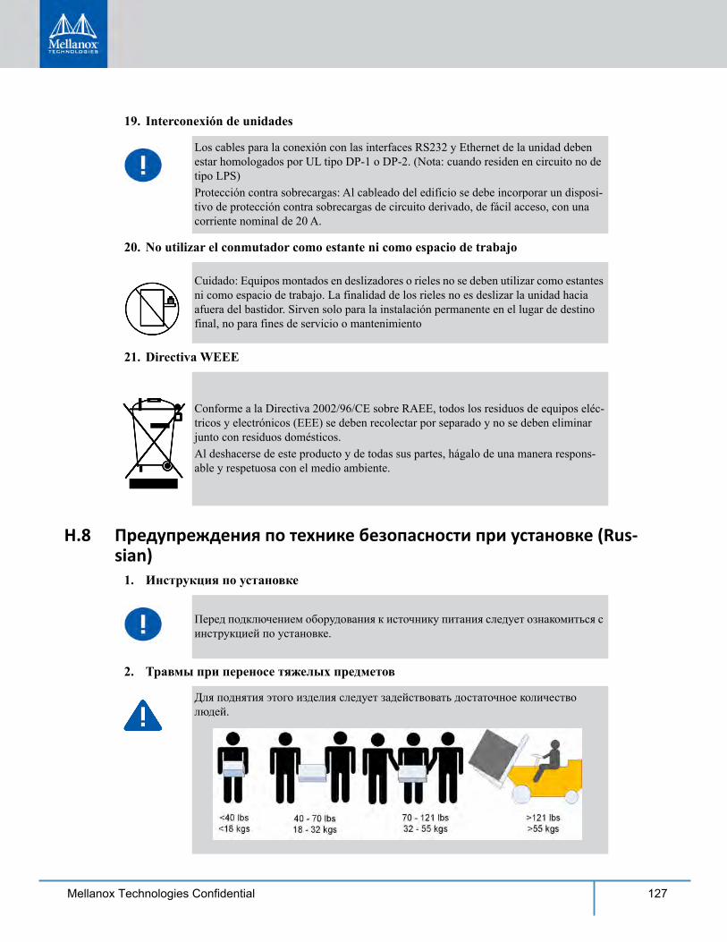
127Mellanox Technologies Confidential
19. Interconexión de unidades
20. No utilizar el conmutador como estante ni como espacio de trabajo
21. Directiva WEEE
H.8 Предупреждения по технике безопасности при установке (Rus-sian)
1. Инструкция по установке
2. Травмы при переносе тяжелых предметов
Los cables para la conexión con las interfaces RS232 y Ethernet de la unidad deben estar homologados por UL tipo DP-1 o DP-2. (Nota: cuando residen en circuito no de tipo LPS)Protección contra sobrecargas: Al cableado del edificio se debe incorporar un disposi-tivo de protección contra sobrecargas de circuito derivado, de fácil acceso, con una corriente nominal de 20 A.
Cuidado: Equipos montados en deslizadores o rieles no se deben utilizar como estantes ni como espacio de trabajo. La finalidad de los rieles no es deslizar la unidad hacia afuera del bastidor. Sirven solo para la instalación permanente en el lugar de destino final, no para fines de servicio o mantenimiento
Conforme a la Directiva 2002/96/CE sobre RAEE, todos los residuos de equipos eléc-tricos y electrónicos (EEE) se deben recolectar por separado y no se deben eliminar junto con residuos domésticos.Al deshacerse de este producto y de todas sus partes, hágalo de una manera respons-able y respetuosa con el medio ambiente.
Перед подключением оборудования к источнику питания следует ознакомиться с инструкцией по установке.
Для поднятия этого изделия следует задействовать достаточное количество людей.
128 Mellanox Technologies Confidential
3. Тяжелое оборудование
4. Опасность поражения электрическим током
5. Перегрев
6. Установка шасси поверх другого оборудования
7. Опасность поражения электрическим током резервного источника питания
8. Несколько источников питания
9. Опасность поражения электрическим током во время грозы
Это тяжелое оборудование, поэтому его следует перемещать с помощью механического подъемника во избежание травм.
Опасность поражения электрическим током!Когда снят вентиляторный модуль, существует возможность повреждения контактов питания в его углублении. НЕ вставлять инструменты или части тела в углубление вентиляторного модуля.
Не эксплуатировать это оборудование в помещении с температурой окружающей среды, превышающей максимально рекомендуемое значение: 45 °C (113 °F). Более того, для надлежащей вентиляции следует обеспечить зазор вокруг вентиляционных отверстий не менее 8 см (3 дюйма).
Не устанавливать шасси поверх другого оборудования. Падение шасси может привести к травмам и повреждению оборудования.
В этом изделии установлен резервный источник питания или модуль-заглушка. Если установлен модуль-заглушка, не эксплуатировать изделие со снятой или ненадежно закрепленной крышкой модуля-заглушки.
Опасность поражения электрическим током и опасные энергетические воздействия.Блоки питания независимы друг от друга.Чтобы обесточить все компоненты внутри платформы коммутации, следует отсоединить все блоки питания.
Во время грозы запрещается использовать оборудование и подключать или отключать кабели.
129Mellanox Technologies Confidential
10. Подсоединение и отсоединение медных кабелей InfiniBand
11. Установка или обслуживание в стойке
12. Установка оборудования
13. Утилизация оборудования
14. Местные и национальные правила установки электрооборудования
15. Правила установки электрооборудования
16. Шнур питания, включенный в номенклатуру UL и сертифицированный Канадской ассоциацией стандартизации (CSA)
Медные кабели InfiniBand тяжелые и негибкие, поэтому следует осторожно их подсоединять и отсоединять. За особыми предупреждениями и указаниями следует обратиться к производителю кабеля.
При установке или обслуживании этого изделия в стойке следует обеспечить устойчивость системы. Как правило, стойка заполняется оборудованием снизу вверх.
Устанавливать, заменять и/или обслуживать это оборудование должен только подготовленный и квалифицированный персонал.
Это оборудование утилизируется в соответствии с национальными законами и постановлениями.
Это оборудование устанавливается в соответствии с местными и национальными правилами установки электрооборудования.
Это устройство устанавливается в соответствии с последним изданием национальных правил установки электрооборудования. В Северной Америке оборудование устанавливается в соответствии с действующими требованиями Национальных правил эксплуатации и обслуживания электрических установок США и Канады.
Подключение к электропитанию в Северной Америке выполняется с помощью шнура питания, включенного в номенклатуру UL и сертифицированного Канадской ассоциацией стандартизации (CSA), 3-жильного, [16 AWG], длиной от 1,5 м [6 футов] до 4,5 м, с литой вилкой, рассчитанной на 125 В [13 А]. Подключение к электропитанию в Европе выполняется с помощью гармонизированного шнура питания с маркировкой <HAR>, 3-жильного, с сечением жилы не менее 1,0 мм², рассчитанного на номинальное напряжение 300 В, с ПВХ оболочкой. Шнур должен иметь литую вилку, рассчитанную на 250 В, 10 А.
130 Mellanox Technologies Confidential
17. Высокий ток утечки
18. Подсоединение устройств
19. Не использовать коммутатор как полку или рабочую
20. Директива WEEE
H.9 Avertismente privind siguranţa la instalare (Romanian)1. Instrucţiuni de instalare
Осторожно! Высокий ток утечки. Заземлить перед подключением к электропитанию.
Для подключения к разъемам RS232 и Ethernet используются кабели типа DP-1 или DP-2, сертифицированные организацией UL. (Примечание. При подключении к сети без ограниченного источника электропитания)Максимальная токовая защита. В проводку здания в легкодоступном месте следует включить устройство защиты от перегрузки по току номиналом 20 А.
Внимание! Оборудование, установленное на направляющих, не должно использоваться как полка или рабочая поверхность. Направляющие не предназначены для удерживания устройства, выдвинутого из стойки. Они предназначены для стационарной установки только в конечном положении и не используются для обслуживания устройства.
В соответствии с Директивой 2002/96/EC (WEEE) отходы электрического и электронного оборудования должны собираться и утилизироваться отдельно от обычных бытовых отходов.Следует утилизировать это изделие и все его части ответственным и экологически безопасным способом.
Citiţi toate instrucţiunile de instalare înainte de a conecta
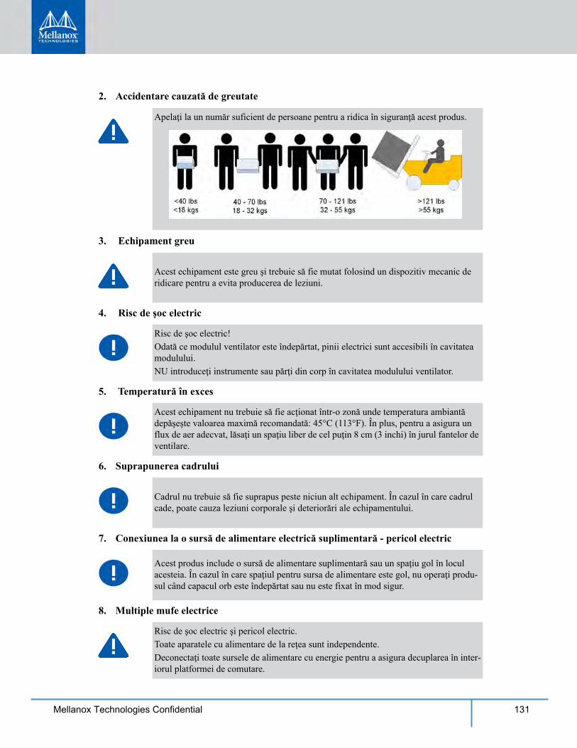
131Mellanox Technologies Confidential
2. Accidentare cauzată de greutate
3. Echipament greu
4. Risc de şoc electric
5. Temperatură în exces
6. Suprapunerea cadrului
7. Conexiunea la o sursă de alimentare electrică suplimentară - pericol electric
8. Multiple mufe electrice
Apelaţi la un număr suficient de persoane pentru a ridica în siguranţă acest produs.
Acest echipament este greu şi trebuie să fie mutat folosind un dispozitiv mecanic de ridicare pentru a evita producerea de leziuni.
Risc de şoc electric!Odată ce modulul ventilator este îndepărtat, pinii electrici sunt accesibili în cavitatea modulului. NU introduceţi instrumente sau părţi din corp în cavitatea modulului ventilator.
Acest echipament nu trebuie să fie acţionat într-o zonă unde temperatura ambiantă depăşeşte valoarea maximă recomandată: 45°C (113°F). În plus, pentru a asigura un flux de aer adecvat, lăsaţi un spaţiu liber de cel puţin 8 cm (3 inchi) în jurul fantelor de ventilare.
Cadrul nu trebuie să fie suprapus peste niciun alt echipament. În cazul în care cadrul cade, poate cauza leziuni corporale şi deteriorări ale echipamentului.
Acest produs include o sursă de alimentare suplimentară sau un spaţiu gol în locul acesteia. În cazul în care spaţiul pentru sursa de alimentare este gol, nu operaţi produ-sul când capacul orb este îndepărtat sau nu este fixat în mod sigur.
Risc de şoc electric şi pericol electric.Toate aparatele cu alimentare de la reţea sunt independente.Deconectaţi toate sursele de alimentare cu energie pentru a asigura decuplarea în inter-iorul platformei de comutare.
132 Mellanox Technologies Confidential
9. În timpul descărcărilor electrice - pericol electric
10. Conectarea/deconectarea cablului din cupru InfiniBand
11. Montarea sau depanarea într-un rack
12. Instalarea echipamentului
13. Eliminarea echipamentului
14. Codurile electrice locale şi naţionale
15. Codurile ed instalare
În timpul perioadelor cu descărcări electrice luminoase, nu lucraţi cu echipamentul sau nu conectaţi sau deconectaţi cablurile.
Cablurile InfiniBand din cupru sunt grele şi inflexibile, de aceea trebuie să fie ataşate sau detaşate de conectori cu grijă. Consultaţi producătorul de cabluri pentru avertis-mente/instrucţiuni speciale.
Când acest produs este montat sau depanat într-un rack, trebuie să fie luate măsuri de precauţie speciale pentru a se asigura că sistemul rămâne stabil. În general, trebuie să umpleţi rack-ul cu echipamente începând de jos în sus.
Acest echipament trebuie să fie instalat, înlocuit şi/sau depanat numai de către personal instruit şi calificat.
Eliminarea acestui echipament trebuie să se realizeze în conformitate cu toate legile şi regulamentele naţionale.
Acest echipament trebuie să fie instalat conform codurilor electrice locale şi naţionale.
Acest dispozitiv trebuie să fie instalat în conformitate cu ultima versiune a codurilor electrice naţionale ale ţării în cauză. Pentru America de Nord, echipamentul trebuie să fie instalat conform cerințelor aplicabile din Codul electric naţional al SUA şi Codul electric canadian.
133Mellanox Technologies Confidential
16. Cordon de alimentare electrică înregistrat UL şi certificat CSA
17. Curent de scurgere de înaltă frecvenţă
18. Interconectarea unităţilor
19. Nu utilizaţi comutatorul ca raft sau spaţiu de lucru
20. Directiva DEEE
Pentru conectarea la o sursă de alimentare pentru America de Nord, selectaţi un cordon de alimentare care este înregistrat UL şi certificat CSA, cu 3 conductoare, [16 AWG], terminat cu o fişă turnată, cu putere nominală egală cu 125 V, [13 A], cu o lungime de minimum 1,5 m [şase picioare], dar nu mai lung de 4,5 m.Pentru conectarea la o sursă de alimentare în Europa, selectaţi un cordon de alimentare care este armonizat la nivel internaţional şi marcat „<HAR>”, cu 3 conductoare, cu minimum 2 fire de 1,0 mm, cu putere nominală egală cu 300 V şi cu o manta izolantă din PVC. Cordonul de alimentare trebuie să fie prevăzut cu o fişă turnată cu putere nominală egală cu 250 V, 10 A.
Avertisment: Curent de scurgere de înaltă frecvenţă; Împământarea este esenţială înainte de a conecta sursa de alimentare.
Cablurile pentru conectarea la unitatea RS232 şi la interfeţele Ethernet trebuie să fie de tipul DP-1 sau DP-2 certificate UL. (Notă- când se regăsesc într-un circuit non-LPS)Protecţie la supracurent: Un dispozitiv de protecţie la supracurent, înregistrat în cir-cuitul de ramificare, uşor accesibil şi cu o putere nominală egală cu 20 A trebuie să fie integrat în cablajul clădirii.
Atenţie: Echipamentul montat pe o linie de alunecare/şină nu va fi utilizat ca raft sau spaţiu de lucru. Scopul şinelor nu este de a glisa unitatea de pe rack. Acestea sunt des-tinate instalării permanente numai la punctul final de oprire şi nu vor fi folosite pentru depanare şi întreţinere
În conformitate cu Directiva DEEE 2002/96/CE, toate deşeurile de echipamente elec-trice şi electronice (EEE) trebuie colectate separat şi nu trebuie eliminate împreună cu deşeurile menajere obişnuite.Eliminaţi acest produs şi toate componentele sale în mod responsabil şi ecologic.
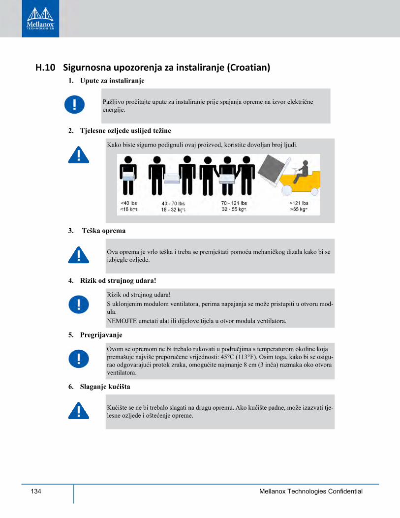
134 Mellanox Technologies Confidential
H.10 Sigurnosna upozorenja za instaliranje (Croatian)1. Upute za instaliranje
2. Tjelesne ozljede uslijed težine
3. Teška oprema
4. Rizik od strujnog udara!
5. Pregrijavanje
6. Slaganje kućišta
Pažljivo pročitajte upute za instaliranje prije spajanja opreme na izvor električne energije.
Kako biste sigurno podignuli ovaj proizvod, koristite dovoljan broj ljudi.
Ova oprema je vrlo teška i treba se premještati pomoću mehaničkog dizala kako bi se izbjegle ozljede.
Rizik od strujnog udara!S uklonjenim modulom ventilatora, perima napajanja se može pristupiti u otvoru mod-ula. NEMOJTE umetati alat ili dijelove tijela u otvor modula ventilatora.
Ovom se opremom ne bi trebalo rukovati u područjima s temperaturom okoline koja premašuje najviše preporučene vrijednosti: 45°C (113°F). Osim toga, kako bi se osigu-rao odgovarajući protok zraka, omogućite najmanje 8 cm (3 inča) razmaka oko otvora ventilatora.
Kućište se ne bi trebalo slagati na drugu opremu. Ako kućište padne, može izazvati tje-lesne ozljede i oštećenje opreme.
135Mellanox Technologies Confidential
7. Redundantno napajanje - Opasnost od električne energije
8. Višestruki ulazi za napajanje
9. Tijekom udara munje - Opasnost od električne energije
10. Spajanje/Odspajanje bakrenog kabela InfiniBand
11. Montaža ormarića i servisiranje
12. Instaliranje opreme
13. Odlaganje opreme
14. Lokalni i nacionalni električni kodovi
Ovaj proizvod uključuje redundantno napajanje ili prazan prostor na njegovu mjestu. U slučaju praznog prostora za napajanje, nemojte rukovati proizvodom ako je pok-lopac uklonjen ili ako nije dobro pričvršćen.
Rizik od strujnog udara i opasnost od električne energije.PSU jedinice su neovisne.Odspojite sva napajanja kako biste osigurali stanje bez napajanja unutar platforme preklopnika.
Tijekom djelovanja munja, nemojte raditi na opremi ili spajati ili odspajati kabele.
Bakreni kabeli InfiniBand su teški i nesavitljivi i kao takvi se moraju pažljivo prikl-jučiti na ili isključiti iz konektora. Obratite se proizvođaču kabela za posebna upo-zorenja/upute.
Kad se proizvod montira ili se servisira u ormariću, moraju se poduzeti posebne mjere opreza kako bi se osiguralo da sustav ostane stabilan. Općenito, trebali biste ispunja-vati ormarić s opremom počevši od dna prema vrhu.
Ovu bi opremu trebalo instalirati, zamjenjivati i/ili servisirati samo obučeno i kvalifici-rano osoblje.
Odlaganje opreme trebalo bi se vršiti sukladno nacionalnim zakonima i propisima.
Ova oprema trebala bi se instalirati u skladu s lokalnim i nacionalnim električnim kodovima.
136 Mellanox Technologies Confidential
15. Instalacijski kodovi
16. UL CSA kabel napajanja
17. Veliko curenje struje
18. Interkonekcija uređaja
19. Nemojte koristiti preklopnik kao policu ili radnu površinu
Ovaj se uređaj mora instalirati sukladno najnovijoj verziji nacionalnih elek-tričnih kodova države. U Sjevernoj Americi oprema se mora instalirati suk-ladno važećim zahtjevima navedenim u US National Electrical Code i Canadian Electrical Code.
Za sjevernoameričku mrežu odaberite kabel napajanja koji je na UL listi i sa CSA certifikatom, 3 - žilni, [16 AWG] (16 AWG) koji završava lijevanim uti-kačem nazivnog napona od 125 V, [13 A], minimalne duljine od 1,5 m [six feet] (šest stopa), ali ne dulji od 4,5 m.Za europsku mrežu odaberite kabel napajanja koji je međunarodno usklađen i označen “<HAR>”, 3 - žilni, s najmanje 1,0 mm2 žice, nazivnog napona od 300 V, s PVC izolacijom. Kabel mora imati lijevani utikač nazivnog napona od 250 V, nazivne struje od 10 A.
Upozorenje: Veliko curenje struje; Prije spajanja napajanja nužno je spojiti uzeml-jenje.
Kabeli za spajanje na jedinicu RS232 i Ethernet sučelja moraju biti s UL cer-tifikatom vrste DP-1 ili DP-2. (Napomena - kad se nalazi u krugu bez LPS vodiča)Zaštita od strujnog preopterećenja: Uvijek dostupni odobreni zaštitni uređaji od strujnog preopterećenja nazivne struje od 20 A moraju se ugraditi u ožičenje zgrade.
Pozor: Oprema montirana na klizače/vodilice ne bi se trebala koristiti kao polica ili radna površina. Vodilice nisu namijenjene za povlačenje uređaja iz ormarića. Služe samo za trajnu instalaciju na konačnom položaju, a ne za servisiranje i održavanje.
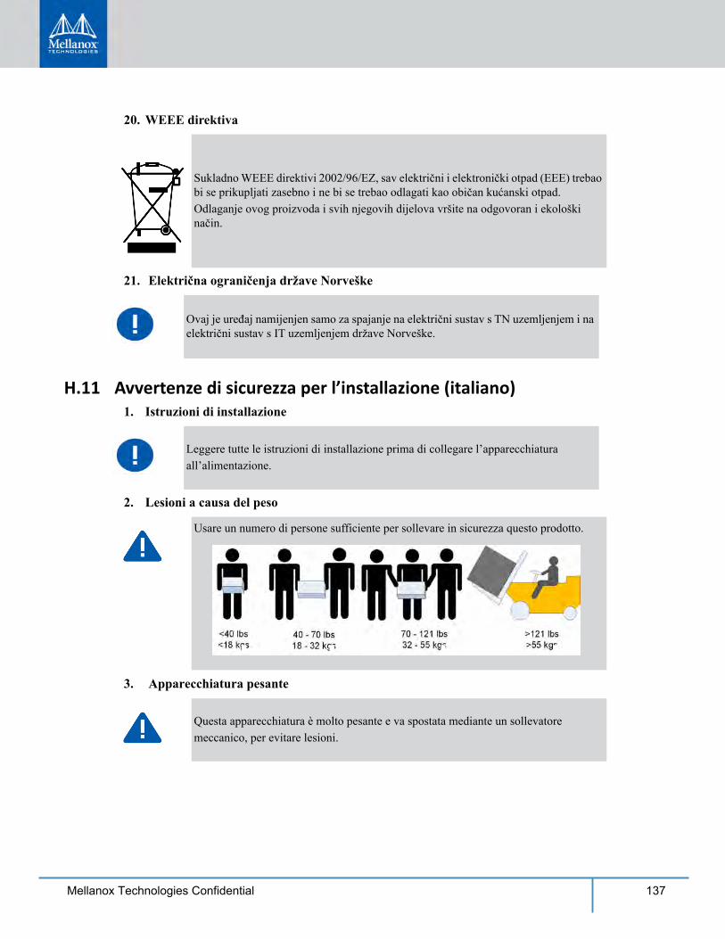
137Mellanox Technologies Confidential
20. WEEE direktiva
21. Električna ograničenja države Norveške
H.11 Avvertenze di sicurezza per l’installazione (italiano)1. Istruzioni di installazione
2. Lesioni a causa del peso
3. Apparecchiatura pesante
Sukladno WEEE direktivi 2002/96/EZ, sav električni i elektronički otpad (EEE) trebao bi se prikupljati zasebno i ne bi se trebao odlagati kao običan kućanski otpad.Odlaganje ovog proizvoda i svih njegovih dijelova vršite na odgovoran i ekološki način.
Ovaj je uređaj namijenjen samo za spajanje na električni sustav s TN uzemljenjem i na električni sustav s IT uzemljenjem države Norveške.
Leggere tutte le istruzioni di installazione prima di collegare l’apparecchiaturaall’alimentazione.
Usare un numero di persone sufficiente per sollevare in sicurezza questo prodotto.
Questa apparecchiatura è molto pesante e va spostata mediante un sollevatoremeccanico, per evitare lesioni.
138 Mellanox Technologies Confidential
4. Rischio di scosse elettriche!
5. Temperatura eccessiva
6. Impilare lo chassis
7. Collegamento di alimentazione ridondante - Pericoli elettrici
8. Prese di alimentazione multiple
9. Durante i temporali, pericolo di scosse elettriche
10. Collegamento/scollegamento del cavo di rame InfiniBand
Rischio di scosse elettriche!Con il modulo ventola rimosso, i pin di alimentazione sono accessibili all’interno dellacavità del modulo.NON inserire strumenti o parti del corpo nella cavità del modulo della ventola.
Questa apparecchiatura non va utilizzata in un’area con una temperatura ambientesuperiore a quella massima consigliata: 45 °C (113 °F). Inoltre, per assicurare unflusso d’aria adeguato, lasciare almeno 8 cm (3 pollici) di spazio attorno alle aperturedi ventilazione.
Kućište se ne bi trebalo slagati na drugu opremu. Ako kućište padne, može izazvati tje-lesne ozljede i oštećenje opreme.
Questo prodotto è dotato di un alimentatore ridondante o, qualora esso non siainstallato, di uno spazio vuoto. Qualora l’alimentatore non sia installato, non utilizzareil prodotto con il coperchio rimosso o non fissato correttamente.
Rischio e pericolo di scosse elettriche.Gli alimentatori sono tutti indipendenti.Scollegare tutti gli alimentatori per assicurarsi che il commutatore non sia sottotensione
Durante i temporali, non effettuare interventi sull’apparecchiatura e non collegare oscollegare i cavi.
I cavi di rame InfiniBand sono pesanti e non flessibili. Di conseguenza, vannocollegati o scollegati con cura dai connettori. Per avvertenze/istruzioni speciali,rivolgersi al produttore di cavi.
139Mellanox Technologies Confidential
11. Montaggio su rack e manutenzione
12. Installazione dell’apparecchiatura
13. Smaltimento dell’apparecchiatura
14. Codici elettrici locali e nazionali
15. Codici di installazione
Questo dispositivo va installato in conformità con l’ultima versione dei codici elettrici nazionali del Paese. Per il Nord America, l’apparecchiatura va installata in conformità con i requisiti applicabili del “codice elettrico nazionale USA” e del “codice elettrico canadese”.
16. Cavo di alimentazione UL e munito di certificazione CSA
Per una connessione di alimentazione nordamericana, selezionare un cavo dialimentazione di tipo UL e munito di certificazione CSA, a 3 conduttori, [16 AWG], terminato con una spina stampata con tensione nominale pari a 125 V, [13 A], di lunghezza minima pari a 1,5 m [sei piedi] ma non più lunga di 4,5 m.Per una connessione europea, selezionare un cavo di alimentazione armonizzato a livello internazionale e contrassegnato da “<HAR>”, a 3 conduttori, minimo 1,0 mm2 fili, con guaina isolante in PVC. Il cavo deve disporre di una spina stampata di potenza nominale pari a 250 V, 10 A.
17. Corrente di dispersione elevata
Quando questo prodotto viene montato o sottoposto a manutenzione su un rack, ènecessario adottare delle precauzioni speciali per assicurarsi che il sistema resti stabile.In generale, il rack va riempito con apparecchiature, procedendo dal basso verso l’alto.
Questa apparecchiatura va installata, sostituita e/o sottoposta a manutenzione solo dapersonale addestrato e qualificato.
Lo smaltimento di questa apparecchiatura va effettuato in conformità con tutte le leggie le normative nazionali.
Questa apparecchiatura va installata in conformità con le norme elettriche locali enazionali.
Avvertenza: corrente di dispersione elevata; il collegamento a terra è essenziale prima di collegare l’alimentazione.
140 Mellanox Technologies Confidential
18. Interconnessione delle unità
I cavi per il collegamento all’unità RS232 e alle interfacce Ethernet devonodisporre della certificazione UL ed essere del tipo DP-1 o DP-2. (Nota: in casodi installazione su un circuito la cui potenza non è limitata)Protezione contro le sovracorrenti: la cablatura dell’edificio deve integrare undispositivo di protezione contro le sovracorrenti di potenza nominale pari a 20.
19. Non utilizzare lo switch come scaffale o piano di lavorol
20. Direttiva RAEE
21. Limitazioni relative all’alimentazione per la Norvegia
Attenzione: un’apparecchiatura scorrevole o montata su binari non va utilizzata comescaffale o piano di lavoro. I binari non sono progettati per far scorrere e allontanarel’unità dal rack. Essi sono destinati all’installazione permanente solo nel luogo dilavoro e non vengono utilizzati per assistenza e manutenzione
Secondo la direttiva RAEE 2002/96/EC, tutti i rifiuti da apparecchiature elettriche edelettroniche (RAEE) vanno raccolti separatamente e non smaltiti nei normali rifiutidomestici.Smaltire questo prodotto e tutte le sue parti in modo responsabile e rispettosodell’ambiente
Questa apparecchiatura è progettata esclusivamente per il collegamento a un sistema dialimentazione TN e a un sistema di alimentazione IT.
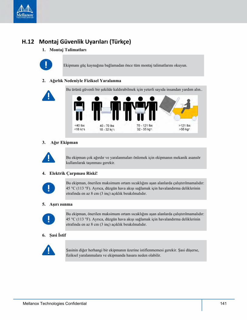
141Mellanox Technologies Confidential
H.12 Montaj Güvenlik Uyarıları (Türkçe)1. Montaj Talimatları
2. Ağırlık Nedeniyle Fiziksel Yaralanma
3. Ağır Ekipman
Bu ekipman çok ağırdır ve yaralanmaları önlemek için ekipmanın mekanik asansör
4. Elektrik Çarpması Riski!
Bu ekipman, önerilen maksimum ortam sıcaklığını aşan alanlarda çalıştırılmamalıdır:45 °C (113 °F). Ayrıca, düzgün hava akışı sağlamak için havalandırma deliklerinin
5. Aşırı ısınma
Bu ekipman, önerilen maksimum ortam sıcaklığını aşan alanlarda çalıştırılmamalıdır:45 °C (113 °F). Ayrıca, düzgün hava akışı sağlamak için havalandırma deliklerinin
6. Şasi İstif
Şasinin diğer herhangi bir ekipmanın üzerine istiflenmemesi gerekir. Şasi düşerse,
Ekipmanı güç kaynağına bağlamadan önce tüm montaj talimatlarını okuyun.
Bu ürünü güvenli bir şekilde kaldırabilmek için yeterli sayıda insandan yardım alın..
kullanılarak taşınması gerekir.
etrafında en az 8 cm (3 inç) açıklık bırakılmalıdır.
etrafında en az 8 cm (3 inç) açıklık bırakılmalıdır.
fiziksel yaralanmalara ve ekipmanda hasara neden olabilir.
142 Mellanox Technologies Confidential
7. Yedekli Güç Kaynaðý Baðlantýsý -Elektrik Çarpma Tehlikesi
Bu ürün, yedekli güç kaynağı veya onun yerine boş elektrik kutusu içerir. Güç kaynağıiçin boş elektrik kutusu varsa, kutunun kapağı açıkken veya tam olarak
8. Çoklu Güç Girişleri
Elektrik çarpması riski ve enerji tehlikesi.Bütün PSU'lar (Güç Kaynağı Üniteleri) ayrıdır.Anahtar platformundaki gücü kapatmak için tüm güç kaynaklarının bağlantılarını
9. Şimşek - Elektrik Çarpma Tehlikesi
Gökyüzünde şimşek çaktığı zamanlarda, ekipman üzerinde çalışmayın veya kablo
10. Bakır İnfiniband Kablo Bağlama/Bağlantıyı Kesme
Bakır İnfiniband kablolar ağırdır ve esnemezler. Bu nedenle, bağlantılara çok dikkatlibir şekilde takılmaları veya çıkarılmaları gerekir. Özel uyarılar/talimatlar için kablo
11. İskele Montajı ve Bakım
Bu ürün bir iskelede monte edildiyse veya bir iskele ile sunulduysa, sistemin sabitkalması için özel önlemler alınmalıdır. Genelde, ekipmanları iskeleye aşağıdan yukarı
12. Ekipman Montajı
Ekipmanın yalnızca eğitimli ve nitelikli personel tarafından monte edilmesi,
13. Ekipmanın Atılması
14. Yerel ve Ulusal Elektrik Kodları
kapatılmamışken ürünü çalıştırmayın.
kesin.
bağlamayın ya da kablo bağlantısı kesmeyin.
üreticinize başvurun.
doğru doldurmanız gerekir.
değiştirilmesi ve/veya bakımının yapılması gerekir.
Bu ekipmanın imhasında tüm ulusal yasalara ve düzenlemelere uyulması gerekir.
Bu ekipmanın montajında yerel ve ulusal elektrik kodlarına uyulması gerekir.
143Mellanox Technologies Confidential
15. Montaj Kodları
16. UL Kayıtlı ve CSA Onaylı Güç Kaynağı Kablosu
Kuzey Amerika'da güç bağlantısı için, UL Kayıtlı ve CSA Onaylı bir güç kaynağıkablosu seçin, 3 - iletken, [16 AWG], 125 V değerinde, kalıplanmış bir fişle biten,[13 A], en az 1,5 m (altı fit) uzunluğunda fakat 4,5 m'den uzun olmayan bir kablo.Avrupa'da güç bağlantısı için, uluslararası uyumlu ve “<HAR>” işaretli,3 - iletken, en az 1,0 mm2 tel, 300 V değerinde ve PVC yalıtımlı bir güçkaynağı kablosu seçin. Kablonun 250 V, 10 A değerinde bir kalıplanmış fişiolması gerekmektedir.
17. Yüksek Kaçak Akım
18. Ünitelerin Ara Bağlantısı
RS232 ünitesini ve Ethernet Arabirimlerini bağlayacak olan kabloların ULonaylı DP-1 veya DP-2 tipi olması gerekir. (Not- LPS olmayan devreye aitse)Aşırı Akım Koruması: Kolayca erişilebilecek 20 V Kayıtlı devre parçası aşırıakım koruma cihazının bina elektrik şebekesinde kurulu olması gerekir.
19. Anahtarı Raf veya Çalışma Alanı olarak kullanmayınl
Dikkat: Sürgülü/raylı ekipman raf veya çalışma alanı olarak kullanılamaz. Raylarüniteyi iskeleden uzağa kaydırmak için yapılmamıştır. Sadece, ekipmanın son olarak
20. WEEE Yönergesi
WEEE Yönergesi 2002/96/EC uyarınca, tüm elektrikli ve elektronik ekipman atıkları(EEE) ayrı olarak toplanmalı ve evsel atıklarla birlikte çöpe atılmamalıdır.
Bu cihazın, ülke ulusal elektrik kodlarının son sürümüne göre monte edilmesigerekir. Kuzey Amerika için, ekipmanın ABD Ulusal Elektrik Kodu veKanada Elektrik Kodu'nun uygulama koşullarına göre monte edilmesi gerekir.
Uyarý: Yüksek kaçak akım varsa; güç kaynağına bağlanmadan önce mutlaka toprak-lama bağlantısı yapılmalıdır.
duracağı yerdeki kalıcı montaj içindir, servis veya bakım için kullanılamaz.
Bu ürün ve tüm parçaları çevreye dost ve sorumlu bir şekilde imha edilmelidir.
144 Mellanox Technologies Confidential
21. Norveç Güç Kısıtlamaları
Bu ünite, bir TN güç sistemine ve sadece Norveç'in IT güç sistemine bağlanmak
H.13 Japan VCCI Class A Statement
H.141.
2.
3.
4.
içindir.
.
.
.
.
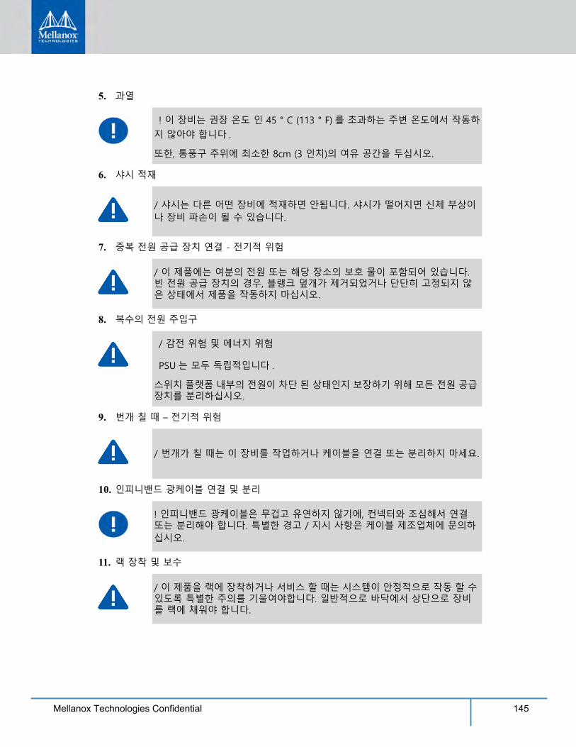
145Mellanox Technologies Confidential
5.
6.
7.
8.
9.
10.
11.
.
..
.
.
.
..
.
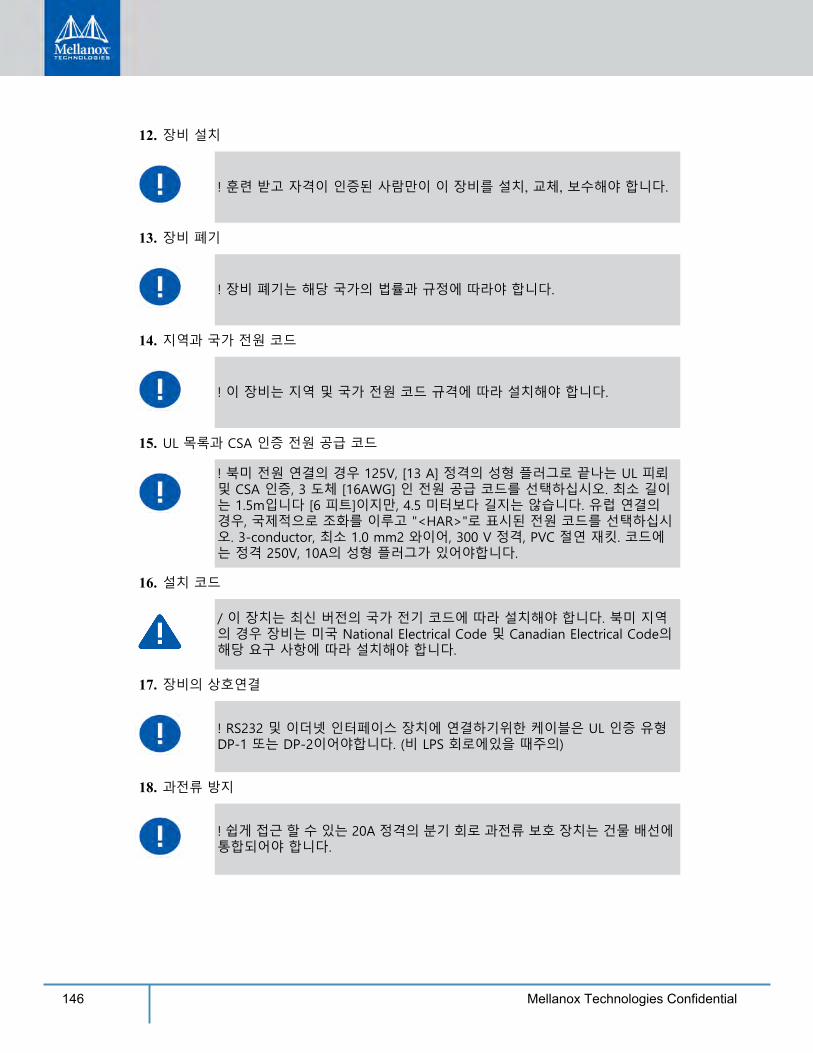
146 Mellanox Technologies Confidential
12.
13.
14.
15.
16.
17.
18.
, , .
.
.
.
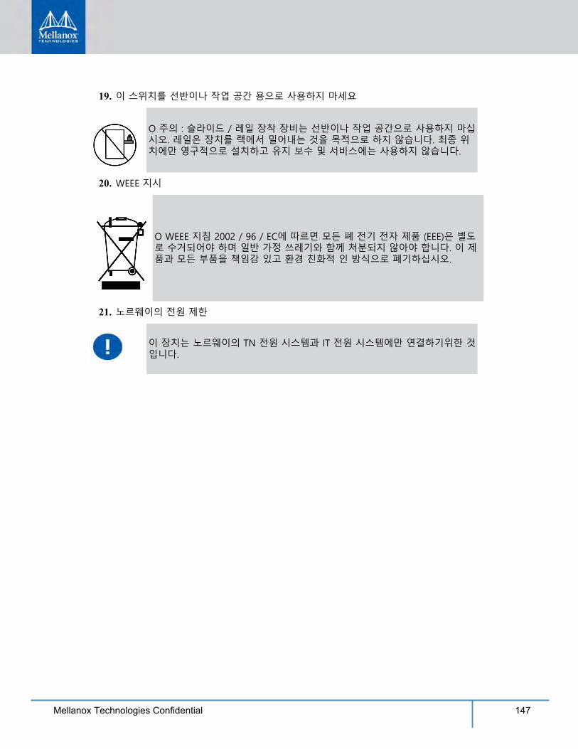
147Mellanox Technologies Confidential
19.
20.
21.
.
.
.