Embed Size (px)
Citation preview
Document Number: EDS 08-5010
Version: 2.0
Date: 14/12/2017
TH
IS IS
AN
UN
CO
NT
RO
LL
ED
DO
CU
ME
NT
, T
HE
RE
AD
ER
MU
ST
CO
NF
IRM
IT
S V
AL
IDIT
Y B
EF
OR
E U
SE
ENGINEERING DESIGN STANDARD
EDS 08-5010
ENERGY STORAGE
Network(s): EPN, LPN, SPN
Summary: This standard provides guidance on the application of energy storage
Author: Jose Barros Date: 14/12/2017
Approver: Sotiris Georgiopoulos Date: 27/12/2017
This document forms part of the Company’s Integrated Business System and its requirements are mandatory throughout UK Power Networks. Departure from these requirements may only be taken with the written approval of the Director of Asset Management. If you have any queries about this document please contact the author or owner of the current issue.
Applicable To
UK Power Networks External
☒ Asset Management ☒ G81 Website
☒ Capital Programme ☐ UK Power Networks Services
☒ Connections ☐ Contractors
☐ Health & Safety ☒ ICPs/IDNOs
☐ Legal ☐ Meter Operators
☒ Network Operations
☐ Procurement
☐ Strategy & Regulation
☐ Technical Training
Energy Storage Document Number: EDS 08-5010
Version: 2.0
Date: 14/12/2017
© UK Power Networks 2018 All rights reserved 2 of 23
Revision Record
Version 2.0 Review Date 27/12/2022
Date 14/12/2017 Author Jose Barros
Reason for update: Periodic review
What has changed: Footnote links updated, Section 4.2 (Different Purposes of Installations) ‘Peak shaving’ updated, ‘System Capacity Services’ added, Section 5.2.1 ‘New Standalone Storage’ updated, Section 5.2.4 ‘Storage in Locations suggested by UKPN’ updated, Section 5.2.5 ‘Storage in Flexible DG Areas’ updated, Section 5.2.6 ‘Notes on LV Connected Storage’ updated.
Appendices removed.
Version 1.0 Review Date 01/09/2017
Date 12/08/2016 Author Jose Barros
New document
Energy Storage Document Number: EDS 08-5010
Version: 2.0
Date: 14/12/2017
© UK Power Networks 2018 All rights reserved 3 of 23
Contents
1 Introduction ............................................................................................................. 5
2 Scope ....................................................................................................................... 5
3 Glossary and Abbreviations ................................................................................... 5
4 Key Concepts .......................................................................................................... 6
4.1 Energy Storage Fundamentals and Technologies ..................................................... 6
4.1.1 Power Rating (MVA or MW) ...................................................................................... 6
4.1.2 Energy Rating (MWh) ................................................................................................ 6
4.2 Different Purposes of Installations ............................................................................. 8
5 Applications ........................................................................................................... 10
5.1 Identifying a Suitable Location for an Application ..................................................... 10
5.2 How Applications are assessed by UK Power Networks .......................................... 11
5.2.1 New Standalone Storage ......................................................................................... 11
5.2.2 New Storage + Generation Proposed at a Known Site ............................................ 12
5.2.3 Storage Additions .................................................................................................... 12
5.2.4 Storage in Locations suggested by UK Power Networks ......................................... 13
5.2.5 Storage in Flexible DG Areas .................................................................................. 13
5.2.6 Notes on LV Connected Storage ............................................................................. 13
6 Specific Network Design and Operation Requirements ..................................... 16
6.1 Thermal Rating of Equipment .................................................................................. 16
6.2 Voltage Regulation .................................................................................................. 16
6.2.1 Steady State Voltage ............................................................................................... 16
6.2.2 Step Voltage Change .............................................................................................. 17
6.3 Power Factor of the Installation ............................................................................... 20
6.4 Security of Supply Regulations (EREC P2/6 Compliance) ....................................... 21
6.5 Power Quality .......................................................................................................... 21
6.6 Additional Requirements for Applications above 50MW and Below 100MW ............ 22
6.7 European Network Codes – Requirements for Generators (RfG) ............................ 22
7 References ............................................................................................................. 23
7.1 UK Power Networks Standards ............................................................................... 23
7.2 National Standards .................................................................................................. 23
8 Dependent Documents.......................................................................................... 23
Table 4-1 – General Response Time of each Energy Storage System by Technology .......... 7
Table 4-2 - Different Routes for Applications including Energy Storage ................................ 9
Table 5-1 - Power quality requirements for equipment connected to public low-voltage mains electricity supply systems .................................................................................. 15
Energy Storage Document Number: EDS 08-5010
Version: 2.0
Date: 14/12/2017
© UK Power Networks 2018 All rights reserved 4 of 23
Table 6-1 - Steady State Voltage Limits According to ESQCR 2002 ................................... 16
Table 6-2 - Typical Network Equivalent Parameters and the Impact on Voltage of 6MVA swings (X/R=4) .................................................................................................. 20
Table 6-3 - Revised wording in Connection Agreements regarding power factor of installations ........................................................................................................ 20
Figure 4-1 – Power Duration Curves for Two Different Energy Ratings ................................. 7
Figure 4-2 – Power Characteristics of the SNS Energy Storage System ............................... 8
Figure 5-1 - Example import/export Limits and "Base Case" Power Flow ............................ 12
Figure 6-1 - Recommended Limit for the Size of Step Voltage Changes with Respect to the Time .................................................................................................................. 18
Figure 6-2 - Multiplication factor for Deriving the Minimum Time between Ramp-type Voltage Changes from the Step Change Limit of Figure 4 (source: EREC P28) ............. 18
Figure 6-3 - Reduced Model for Step Voltage Change Calculations .................................... 19
Energy Storage Document Number: EDS 08-5010
Version: 2.0
Date: 14/12/2017
© UK Power Networks 2018 All rights reserved 5 of 23
1 Introduction
This standard provides guidance on the application of energy storage. Energy Storage has been highlighted as a key technology in the development of smart grids and covers a broad range of technologies, scales and operating models.
In 2012 UK Power Networks launched the Smarter Network Storage (SNS) project, an innovation project to trial the operation of large-scale battery energy storage and novel commercial arrangements in order to explore and resolve some of the non-technical, commercial and economic challenges around storage adoption under different business models.
Over the duration of the project, the energy storage market has been rapidly maturing, and there is now significant interest from developers and investors looking to take advantage of growing opportunities in the deployment and operation of storage, under similar models to that developed and trialled in SNS.
The purpose of this document is to:
Provide sufficient background and guidance to assist customers with their application requests involving energy storage;
Propose “good connection practices” for applications involving energy storage in order to guarantee compliance with License Conditions and relevant Engineering Recommendations.
2 Scope
This standard applies to the connection of energy storage devices to all operating voltages on UK Power Networks distribution networks.
3 Glossary and Abbreviations
Term Definition
PCC Point of Common Coupling
SNS Smarter Network Storage
TSO Transmission System Operator
UK Power Networks UK Power Networks (Operations) Ltd consists of three electricity distribution networks:
• Eastern Power Networks plc (EPN). • London Power Network plc (LPN). • South Eastern Power Networks plc (SPN).
Energy Storage Document Number: EDS 08-5010
Version: 2.0
Date: 14/12/2017
© UK Power Networks 2018 All rights reserved 6 of 23
4 Key Concepts
4.1 Energy Storage Fundamentals and Technologies
Energy storage can come in a wide variety of forms, ranging from the large-scale pumped hydro schemes that provide national balancing, to the very small-scale electro-chemical storage which is typically used in laptops and mobiles. The storage medium can be either in the form of electricity, such as in supercapacitors, electrochemical form, such as in batteries, or even heat or gas.
All of these technologies have different operating characteristics, response times, and advantages/disadvantages, which make them more or less effective for different applications and at different scales. However, most can be simply characterised by their fundamental ability to deliver power and energy to the network. There are two key ratings that determine the overall characteristics of storage:
4.1.1 Power Rating (MVA or MW)
This describes the maximum power at which the storage can push (or pull) power onto (or from) the network, and drives the maximum import and export capacity required at the connection point to operate at full power, (an analogy being the size of the engine of a car, or how fast it can go).
Most storage control systems allow for the import and export to be controlled at any rate up to the maximum power rating. Hence, if the storage has a 3MW rating it can both charge and discharge at any power level up to a maximum of 3MW.
4.1.2 Energy Rating (MWh)
This describes the energy duration or energy capacity of the storage device, and can be used to determine how long the storage could import (or export) for at a given power (the analogy being the size of the petrol tank, or how long it can run for until empty).
Different storage technologies scale differently in terms of power and energy rating, with some being expensive to add additional energy duration, whereas others may be more costly to add additional power capability.
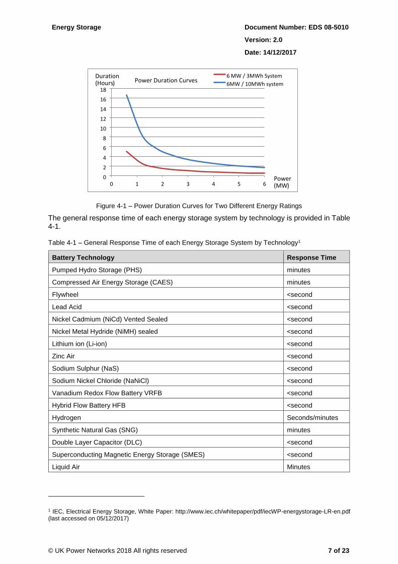
The duration for which a storage system can sustain export (or import) to (or from) the network at maximum power, can be determined by dividing energy rating by power rating. For example, the SNS system, which is rated at 6MW / 10MWh, can provide 10/6 = 1.67 hours or around 100 minutes of import (or export) at maximum power of 6MW. This is illustrated further in the example power duration curves of Figure 4-1, which show the duration for which a response can be provided (import or export), at a given power level for two different example rated systems.
An “Energy to Power” ratio of 1 or below (i.e. energy rating similar or lower than rated power) means the energy storage device will be more suited for power delivery of one hour or less with full power, due to limited capacity availability. Conversely, an “Energy to Power” ratio above 1 means the delivery of power may be sustained for longer periods.
Energy Storage Document Number: EDS 08-5010
Version: 2.0
Date: 14/12/2017
© UK Power Networks 2018 All rights reserved 7 of 23
Figure 4-1 – Power Duration Curves for Two Different Energy Ratings
The general response time of each energy storage system by technology is provided in Table 4-1.
Table 4-1 – General Response Time of each Energy Storage System by Technology1
Battery Technology Response Time
Pumped Hydro Storage (PHS) minutes
Compressed Air Energy Storage (CAES) minutes
Flywheel <second
Lead Acid <second
Nickel Cadmium (NiCd) Vented Sealed <second
Nickel Metal Hydride (NiMH) sealed <second
Lithium ion (Li-ion) <second
Zinc Air <second
Sodium Sulphur (NaS) <second
Sodium Nickel Chloride (NaNiCl) <second
Vanadium Redox Flow Battery VRFB <second
Hybrid Flow Battery HFB <second
Hydrogen Seconds/minutes
Synthetic Natural Gas (SNG) minutes
Double Layer Capacitor (DLC) <second
Superconducting Magnetic Energy Storage (SMES) <second
Liquid Air Minutes
1 IEC, Electrical Energy Storage, White Paper: http://www.iec.ch/whitepaper/pdf/iecWP-energystorage-LR-en.pdf (last accessed on 05/12/2017)
0
2
4
6
8
10
12
14
16
18
0 1 2 3 4 5 6
6 MW / 3MWh System 6 MW / 10MWh system
Duration ) ( Hours
Power ( MW )
Power Duration Curves
Energy Storage Document Number: EDS 08-5010
Version: 2.0
Date: 14/12/2017
© UK Power Networks 2018 All rights reserved 8 of 23
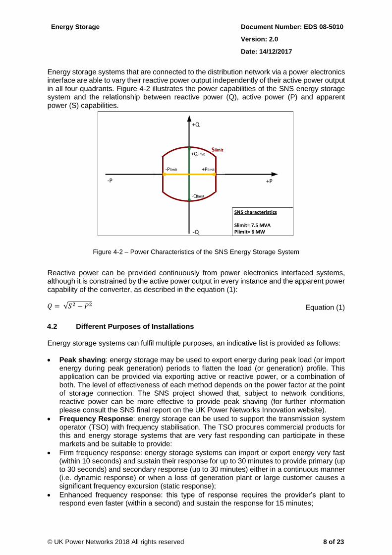
Energy storage systems that are connected to the distribution network via a power electronics interface are able to vary their reactive power output independently of their active power output in all four quadrants. Figure 4-2 illustrates the power capabilities of the SNS energy storage system and the relationship between reactive power (Q), active power (P) and apparent power (S) capabilities.
Figure 4-2 – Power Characteristics of the SNS Energy Storage System
Reactive power can be provided continuously from power electronics interfaced systems, although it is constrained by the active power output in every instance and the apparent power capability of the converter, as described in the equation (1):
Equation (1)
4.2 Different Purposes of Installations
Energy storage systems can fulfil multiple purposes, an indicative list is provided as follows:
Peak shaving: energy storage may be used to export energy during peak load (or import energy during peak generation) periods to flatten the load (or generation) profile. This application can be provided via exporting active or reactive power, or a combination of both. The level of effectiveness of each method depends on the power factor at the point of storage connection. The SNS project showed that, subject to network conditions, reactive power can be more effective to provide peak shaving (for further information please consult the SNS final report on the UK Power Networks Innovation website).
Frequency Response: energy storage can be used to support the transmission system operator (TSO) with frequency stabilisation. The TSO procures commercial products for this and energy storage systems that are very fast responding can participate in these markets and be suitable to provide:
Firm frequency response: energy storage systems can import or export energy very fast (within 10 seconds) and sustain their response for up to 30 minutes to provide primary (up to 30 seconds) and secondary response (up to 30 minutes) either in a continuous manner (i.e. dynamic response) or when a loss of generation plant or large customer causes a significant frequency excursion (static response);
Enhanced frequency response: this type of response requires the provider’s plant to respond even faster (within a second) and sustain the response for 15 minutes;
-Q
+Q
-P +P
+Qlimit
-Qlimit
+Plimit-Plimit
SNS characteristics
Slimit= 7.5 MVAPlimit= 6 MW
Slimit
Energy Storage Document Number: EDS 08-5010
Version: 2.0
Date: 14/12/2017
© UK Power Networks 2018 All rights reserved 9 of 23
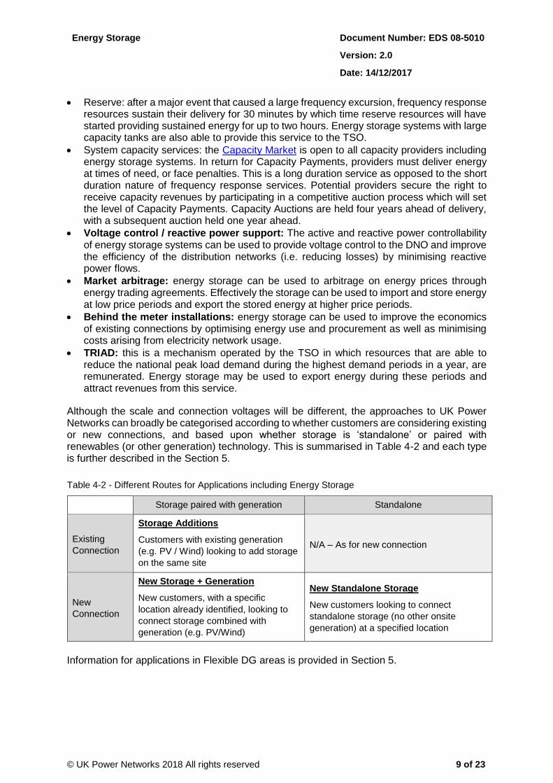
Reserve: after a major event that caused a large frequency excursion, frequency response resources sustain their delivery for 30 minutes by which time reserve resources will have started providing sustained energy for up to two hours. Energy storage systems with large capacity tanks are also able to provide this service to the TSO.
System capacity services: the Capacity Market is open to all capacity providers including energy storage systems. In return for Capacity Payments, providers must deliver energy at times of need, or face penalties. This is a long duration service as opposed to the short duration nature of frequency response services. Potential providers secure the right to receive capacity revenues by participating in a competitive auction process which will set the level of Capacity Payments. Capacity Auctions are held four years ahead of delivery, with a subsequent auction held one year ahead.
Voltage control / reactive power support: The active and reactive power controllability of energy storage systems can be used to provide voltage control to the DNO and improve the efficiency of the distribution networks (i.e. reducing losses) by minimising reactive power flows.
Market arbitrage: energy storage can be used to arbitrage on energy prices through energy trading agreements. Effectively the storage can be used to import and store energy at low price periods and export the stored energy at higher price periods.
Behind the meter installations: energy storage can be used to improve the economics of existing connections by optimising energy use and procurement as well as minimising costs arising from electricity network usage.
TRIAD: this is a mechanism operated by the TSO in which resources that are able to reduce the national peak load demand during the highest demand periods in a year, are remunerated. Energy storage may be used to export energy during these periods and attract revenues from this service.
Although the scale and connection voltages will be different, the approaches to UK Power Networks can broadly be categorised according to whether customers are considering existing or new connections, and based upon whether storage is ‘standalone’ or paired with renewables (or other generation) technology. This is summarised in Table 4-2 and each type is further described in the Section 5.
Table 4-2 - Different Routes for Applications including Energy Storage
Storage paired with generation Standalone
Existing
Connection
Storage Additions
Customers with existing generation
(e.g. PV / Wind) looking to add storage
on the same site
N/A – As for new connection
New
Connection
New Storage + Generation
New customers, with a specific
location already identified, looking to
connect storage combined with
generation (e.g. PV/Wind)
New Standalone Storage
New customers looking to connect
standalone storage (no other onsite
generation) at a specified location
Information for applications in Flexible DG areas is provided in Section 5.

Energy Storage Document Number: EDS 08-5010
Version: 2.0
Date: 14/12/2017
© UK Power Networks 2018 All rights reserved 10 of 23
5 Applications
5.1 Identifying a Suitable Location for an Application
Customers have the following means at present to identify suitable locations for their power requirements ahead of an application:
Generation and demand interactive heat map, available at http://dgmap.ukpowernetworks.co.uk (registration required).
Long Term Development Statement (LTDS) - registration required.
Distributed Generation Surgeries (running on a monthly basis on both EPN and LPN/SPN, pre-registration required.
The generation and demand interactive heat maps provides an understanding of the level of export and import constraint throughout the network.
The Long Term Development Statement provides a rough indication of the level of import constraint on individual substations. This is available on tab “Table 3 – Load Data” of the spreadsheet that accompanies the network single line diagrams. In “Table 3 – Load Data”, the customer can estimate the import headroom by subtracting from column “Firm Capacity MW” the “Forecast (Maximum Demand) MW” for the year he is looking to energise. It must be reiterated that this provides only an indicative view, as:
Tables only show recorded and forecasted values. They do not include unused contracted capacity and accepted but not yet connected capacity;
Interaction between sites needs to be taken into account (e.g. existing capacity at a given primary site is dominated by the lack of capacity of the upstream grid site);
Potential restrictions introduced by security of supply regulations (P2/6) are not included. These would be identified by UK Power Networks following an application.
The load information included in the Long Term Development Statement and other reports UK Power Networks is obliged to provide (e.g. Load Index report to Ofgem) serves as a basis for the demand interactive heat map. However, the information provided is is subject to the same caveats mentioned above for the Long Term Development Statement.
Distributed Generation surgeries provide customers with the opportunity to discuss (face to face or via web/teleconference) project viability in advance of an application.
Energy Storage Document Number: EDS 08-5010
Version: 2.0
Date: 14/12/2017
© UK Power Networks 2018 All rights reserved 11 of 23
5.2 How Applications are assessed by UK Power Networks
The assessment of applications including energy storage requires information in addition to that supplied by the existing generation application form (commonly known as “ENA form”). This is due to the varying operational regimes of energy storage (as described in Section 4.2), which will correspond to different power output profiles. Therefore, UK Power Networks created in September 2015 a “supplementary information form” specific to energy storage applicants. The aim was to identify the customer’s specific requirements to ensure an accurate engineering assessment and offer the most efficient connection solution. This supplementary information form was superseded in April 2016 by the “Further Information Request” form produced by the ENA.
Guidelines for assessing applications including energy storage are provided in Sections 4.2.1 to 4.2.6. Note that Sections 5.2.1 to 5.2.5 are more directed to EREC G59 applications and Section 5.2.6 is typically targeted to EREC G83 applications.
5.2.1 New Standalone Storage
The following high-level planning guidelines are in place to assess a new standalone energy storage application in all License Areas of UK Power Networks:
1. Analyse customer requirements, per ENA form and “Further Information Request” form.
2. Identify the least costly overall connection solution that satisfies the following checks, both
on import (demand) and export (generation):
Capacity limits on circuits/switchgear/transformers on intact and contingent operation scenarios. Seasonal limits to be considered where applicable. Ratings of circuits as defined in EREC P17 and EREC P27 are considered.
Protection limits (e.g., directional overcurrent, overvoltage).
Voltage regulation, particularly voltage step change. Compliance with EREC P28 and statutory limits, as stipulated by ESQCR 2002, to be guaranteed at all times.
Consideration of network complexity regulations, as defined on EREC P18.
Consideration of unused contracted capacity of existing customers.
Consideration of capacity reserved for accepted and not yet connected generators/demand customers.
Compliance with Security of Supply regulations (EREC P2/6).
Interaction with planned network interventions / reinforcements.
Consideration of forecasted load growth.
Consideration of forecasted microgeneration growth.
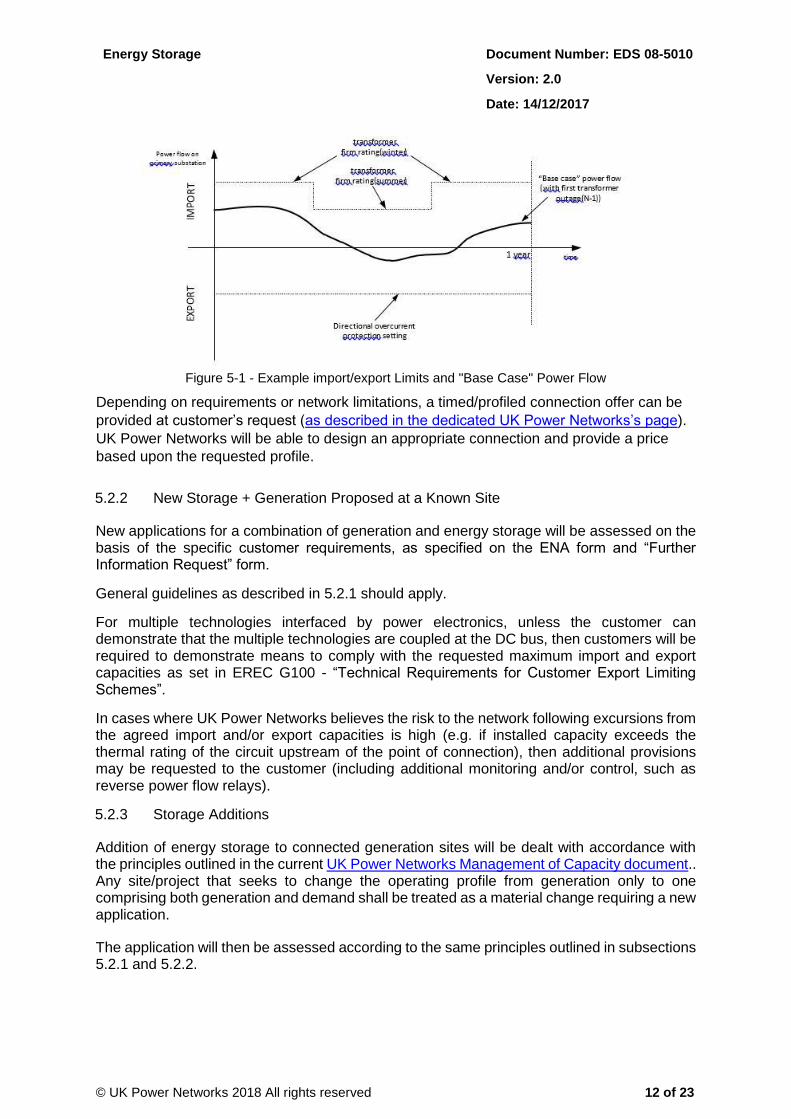
An example of a planning scenario for the connection of energy storage to a primary substation is presented in Figure 5-1. The import is limited by the firm capacity of the substation. The export is limited by the directional overcurrent protection settings.
Energy Storage Document Number: EDS 08-5010
Version: 2.0
Date: 14/12/2017
© UK Power Networks 2018 All rights reserved 12 of 23
Figure 5-1 - Example import/export Limits and "Base Case" Power Flow
Depending on requirements or network limitations, a timed/profiled connection offer can be
provided at customer’s request (as described in the dedicated UK Power Networks’s page).
UK Power Networks will be able to design an appropriate connection and provide a price
based upon the requested profile.
5.2.2 New Storage + Generation Proposed at a Known Site
New applications for a combination of generation and energy storage will be assessed on the basis of the specific customer requirements, as specified on the ENA form and “Further Information Request” form.
General guidelines as described in 5.2.1 should apply.
For multiple technologies interfaced by power electronics, unless the customer can demonstrate that the multiple technologies are coupled at the DC bus, then customers will be required to demonstrate means to comply with the requested maximum import and export capacities as set in EREC G100 - “Technical Requirements for Customer Export Limiting Schemes”.
In cases where UK Power Networks believes the risk to the network following excursions from the agreed import and/or export capacities is high (e.g. if installed capacity exceeds the thermal rating of the circuit upstream of the point of connection), then additional provisions may be requested to the customer (including additional monitoring and/or control, such as reverse power flow relays).
5.2.3 Storage Additions
Addition of energy storage to connected generation sites will be dealt with accordance with the principles outlined in the current UK Power Networks Management of Capacity document.. Any site/project that seeks to change the operating profile from generation only to one comprising both generation and demand shall be treated as a material change requiring a new application.
The application will then be assessed according to the same principles outlined in subsections 5.2.1 and 5.2.2.
Energy Storage Document Number: EDS 08-5010
Version: 2.0
Date: 14/12/2017
© UK Power Networks 2018 All rights reserved 13 of 23
5.2.4 Storage in Locations suggested by UK Power Networks
UK Power Networks has started to procure flexibility response in areas where it is required to support its network operation (e.g. post-fault demand side response). These needs are identified and procured through tender events, as described in a dedicated page on UK Power Networks’s website.
5.2.5 Storage in Flexible DG Areas
Active network management (ANM) systems used to date in Flexible DG areas monitor selected network locations. Upon inadequate capacity conditions, generators are asked to reduce their output to bring the network to acceptable operation. Generators have been assigned to date on the basis of a priority list (“last-in, first-off”) or a shared effort (“pro rata” or “quota”). Generators are brought to normal operation when a reset threshold (typically a fraction of the constraint trigger) is reached.
In order to produce curtailment estimates, a unique operation profile for energy storage (import/export profile) needs to be defined. This import/export profile has been constructed in ANM deployments to date as follows:
Analyse customer requirements, as per ENA form and “Further Information Request” form.
Where a specific import/export profile could not be determined from the customer’s information, a conservative profile for a standalone energy storage system is set as follows:
Import not considered (if no load-related constraints have been identified, as constraints in Flexible DG areas are predominantly export dominated);
0.5 p.u. “flat” export all year round, with the exception of November to February. Between November and February, Monday to Friday between 16.00 and 18.30 hours, 1 p.u. flat export is assumed. This is to capture interest in targeting TRIAD periods.
This conservative profile is intended to represent an “allowance” to cater for the various operating regimes of energy storage (generally export-related), whilst trying to minimise impact on curtailment estimates for other customers. An indication of the level of constraint and time of constraint suffered by the customer is provided in the feasibility reports issued to customers.
5.2.6 Notes on LV Connected Storage
According to Part VI of the “Electricity Safety, Quality and Continuity Regulations (ESQCR) 2002”, no person shall install or operate a source of energy which may be connected in parallel with a distributor’s network unless certain criteria are met. These criteria are covered off in EREC G83 and EREC G59.
A charged domestic storage system is a source of energy. If it is connected in parallel with a distribution network then it shall comply with either EREC G83 or EREC G59 (the only exception would be if it is used as an alternative source of energy and is never paralleled with the network). To comply with EREC G83, the aggregated capacity of all sources of energy within a single customer premises should be 16A per phase or below and use type tested equipment. Where the aggregated capacity is greater than 16A per phase or the equipment is not type tested then it falls under EREC G59. EREC G59 differentiates between <50kW type tested systems and >50kW or non-type tested systems. EREC G59 allows for either EREC G59 or EREC G83 type tested inverters to be used for the interface.
Energy Storage Document Number: EDS 08-5010
Version: 2.0
Date: 14/12/2017
© UK Power Networks 2018 All rights reserved 14 of 23
If the network is not capable of accepting an EREC G59 installation without reinforcement, then it will be necessary to ensure export is limited per the requirements set by EREC G100..
UK Power Networks is keen to work with manufacturers and installers to ensure equipment is designed and installed at minimum cost, whilst balancing the requirements of existing customers and ensuring compliance with our Licence Conditions. EREC G100 states that witnessing of sub-50 kW Export Limitation Schemes would be at the discretion of the DNO. Once customers are able to demonstrate that export limitation schemes are fail-safe, the requirement to witness these small sites should significantly reduce.
UK Power Networks has an online “fast track” tool2 to deal with small scale storage applications. Applications are evaluated online and permission to connect through the fast track process is granted when set technical criteria are met and a supply upgrade is not required.
5.2.6.1 Multiple Energy Sources within a Single Installation
Where the total aggregated capacity of an installation with multiple energy sources within a single installation (including energy storage) is less than 16A per phase, no prior approval is required and the installation would be treated as a normal EREC G83 application. In line with EREC G83, the installed capacity when an inverter is used is deemed to be the inverters steady state rating and not the capacity of the generation connected to the DC side. Below is an example:
If 4kW PV and 2kW energy storage devices are both connected to the DC side of one 3.68kW G83 type tested inverter, then the site complies with G83.
If the same 4kW PV and 2kW energy storage devices are each connected through individual 3.68kW and 2kW inverters respectively, and connected together on the AC side of the installation, then the total installed capacity is assessed as 3.68 + 2 = 5.68kW and must therefore be treated as an EREC G59 application (noting that this could fall under the fast track or simplified G59 application processes). This should be the case even if it is not intended to operate both energy sources at the same time. If the engineering assessment concluded that the local LV network could not support 5.68kW of export then an approved export limiting scheme (as per EREC G100) would need to be installed.
5.2.6.2 Multiple G83 Applications in a Close Geographic Area
For multiple G83 applications in a close geographic area, an engineering assessment in accordance with EREC G83-2 section 5.2.1 is required to make sure the local LV connection can support them. This may also drive the need for export limiting schemes per EREC G100.
5.2.6.3 Standalone Energy Storage Applications
For import/export less than 16A per phase, standalone energy storage devices do not require prior approval and the installation would be treated as a normal EREC G83 application, with notification of installation provided to UK Power Networks within 28 days of the installation.
Should import/export requirements exceed 16A per phase, the installation would be treated as a normal EREC G59 application.
2 can be found at http://www.ukpowernetworks.co.uk/internet/en/our-services/list-of-services/small-scale-storage/
Energy Storage Document Number: EDS 08-5010
Version: 2.0
Date: 14/12/2017
© UK Power Networks 2018 All rights reserved 15 of 23
5.2.6.4 Power Quality Requirements
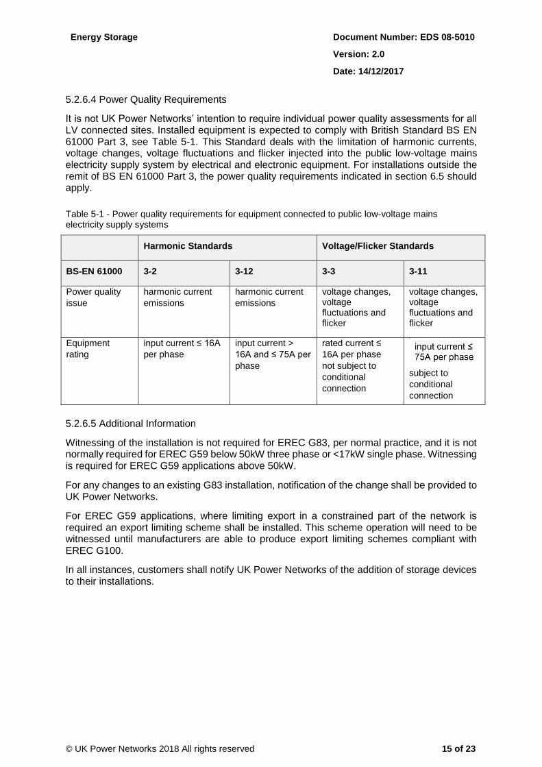
It is not UK Power Networks’ intention to require individual power quality assessments for all LV connected sites. Installed equipment is expected to comply with British Standard BS EN 61000 Part 3, see Table 5-1. This Standard deals with the limitation of harmonic currents, voltage changes, voltage fluctuations and flicker injected into the public low-voltage mains electricity supply system by electrical and electronic equipment. For installations outside the remit of BS EN 61000 Part 3, the power quality requirements indicated in section 6.5 should apply.
Table 5-1 - Power quality requirements for equipment connected to public low-voltage mains electricity supply systems
Harmonic Standards Voltage/Flicker Standards
BS-EN 61000 3-2 3-12 3-3 3-11
Power quality
issue harmonic current
emissions harmonic current
emissions voltage changes, voltage fluctuations and flicker
voltage changes, voltage fluctuations and flicker
Equipment rating
input current ≤ 16A
per phase input current >
16A and ≤ 75A per
phase
rated current ≤
16A per phase
not subject to
conditional
connection
subject to
conditional
connection
5.2.6.5 Additional Information
Witnessing of the installation is not required for EREC G83, per normal practice, and it is not normally required for EREC G59 below 50kW three phase or <17kW single phase. Witnessing is required for EREC G59 applications above 50kW.
For any changes to an existing G83 installation, notification of the change shall be provided to UK Power Networks.
For EREC G59 applications, where limiting export in a constrained part of the network is required an export limiting scheme shall be installed. This scheme operation will need to be witnessed until manufacturers are able to produce export limiting schemes compliant with EREC G100.
In all instances, customers shall notify UK Power Networks of the addition of storage devices to their installations.
Energy Storage Document Number: EDS 08-5010
Version: 2.0
Date: 14/12/2017
© UK Power Networks 2018 All rights reserved 16 of 23
6 Specific Network Design and Operation Requirements
A number of technical considerations are taken into account when assessing new energy storage applications to ensure that safe and reliable network operation will be maintained.
Network design and operation requirements are more likely to be satisfied when connections are made directly at primary/grid substations, depending on power requirements, and at higher voltage levels. Also, consideration of different import and export power requirements (depending of the intended purpose(s) for the energy storage device) may facilitate the connection, particularly on the point of view of thermal rating of equipment, voltage regulation and security of supply.
Information on the most relevant technical aspects for an energy storage application assessment is covered in sections 6.1 to 6.7.
6.1 Thermal Rating of Equipment
Distribution network equipment is designed to be operated within specified loading limits. The loading limits of each asset, e.g. cable, transformer, etc, are a function of the heat that equipment may withstand. These limits vary with installation conditions. UK Power Networks operates its assets as recommended in relevant Engineering Recommendations, such as EREC P17 (underground cables) and EREC P27 (overhead lines), and as set in internal operating standards as EOS 04-1020 for transformer ratings3.
If a customer only wishes to utilise the network beyond a defined power for limited periods of time (e.g. up to a few minutes per hour) and risk to network operation is perceived to be acceptable, then appropriate commercial agreements and monitoring/control solutions (such as export limiting schemes and timers) may be implemented to accommodate this. Another option currently being trialled is the use of profiled connections (see Appendices).
6.2 Voltage Regulation
6.2.1 Steady State Voltage
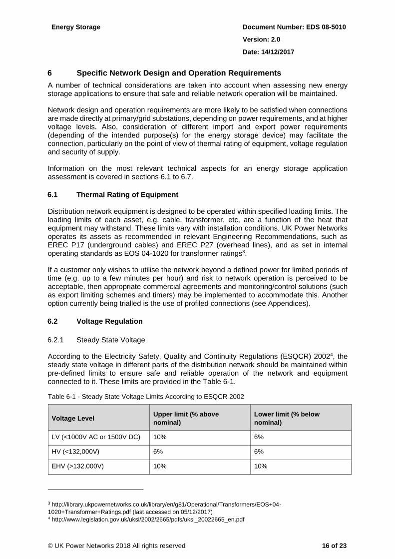
According to the Electricity Safety, Quality and Continuity Regulations (ESQCR) 20024, the steady state voltage in different parts of the distribution network should be maintained within pre-defined limits to ensure safe and reliable operation of the network and equipment connected to it. These limits are provided in the Table 6-1.
Table 6-1 - Steady State Voltage Limits According to ESQCR 2002
Voltage Level Upper limit (% above
nominal) Lower limit (% below
nominal)
LV (<1000V AC or 1500V DC) 10% 6%
HV (<132,000V) 6% 6%
EHV (>132,000V) 10% 10%
3 http://library.ukpowernetworks.co.uk/library/en/g81/Operational/Transformers/EOS+04-
1020+Transformer+Ratings.pdf (last accessed on 05/12/2017) 4 http://www.legislation.gov.uk/uksi/2002/2665/pdfs/uksi_20022665_en.pdf
Energy Storage Document Number: EDS 08-5010
Version: 2.0
Date: 14/12/2017
© UK Power Networks 2018 All rights reserved 17 of 23
Voltage is affected by the load/generation balance in every instant. When energy storage devices export electricity, the voltage at their terminals is increased. The opposite occurs when energy storage devices import electricity. Specific studies using load flow software are conducted to evaluate whether the operation of the energy storage device will impact the steady state voltage of the distribution network.
6.2.2 Step Voltage Change
Single variations of the rms value or peak value of the supply voltage are called step changes. The step changes in voltage are dependent on sudden changes in the demand/supply balance. Step changes caused by a customer are measured at the point of common coupling.
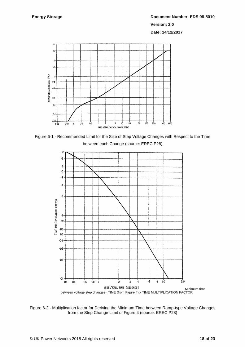
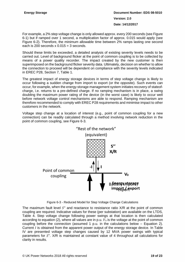
EREC 28 prescribes limits for step and ramp voltage changes with respect to the time between each change, as shown in Figure 6-1 and Figure 6-2. The 3% limit illustrated in Figure 6-1 is flexed to 10% only for unplanned events, such as faults, that are not expected to occur more frequently than once a year.
Energy Storage Document Number: EDS 08-5010
Version: 2.0
Date: 14/12/2017
© UK Power Networks 2018 All rights reserved 18 of 23
Figure 6-1 - Recommended Limit for the Size of Step Voltage Changes with Respect to the Time
between each Change (source: EREC P28)
Minimum time between voltage step changes= TIME (from Figure 4) x TIME MULTIPLICATION FACTOR
Figure 6-2 - Multiplication factor for Deriving the Minimum Time between Ramp-type Voltage Changes from the Step Change Limit of Figure 4 (source: EREC P28)
Energy Storage Document Number: EDS 08-5010
Version: 2.0
Date: 14/12/2017
© UK Power Networks 2018 All rights reserved 19 of 23
For example, a 2% step voltage change is only allowed approx. every 200 seconds (see Figure 6-1) but if ramped over 1 second, a multiplication factor of approx. 0.015 would apply (see Figure 6-2). Therefore, the minimum allowable time between 2% ramps lasting one second each is 200 seconds x 0.015 = 3 seconds.
Should these limits be exceeded, a detailed analysis of existing severity levels needs to be carried out. Level of background flicker at the point of common coupling is to be collected by means of a power quality recorder. The impact created by the new customer is then superimposed on the background flicker severity data. Ultimately, decision on whether to allow the connection to proceed will be dependent on compliance with the severity levels indicated in EREC P28, Section 7, Table 1.
The greatest impact of energy storage devices in terms of step voltage change is likely to occur following a sudden change from import to export (or the opposite). Such events can occur, for example, when the energy storage management system initiates recovery of stateof-charge, i.e. returns to a pre-defined charge. If no ramping mechanism is in place, a swing doubling the maximum power rating of the device (in the worst case) is likely to occur well before network voltage control mechanisms are able to respond. Ramping mechanism are therefore recommended to comply with EREC P28 requirements and minimise impact to other customers in the network.
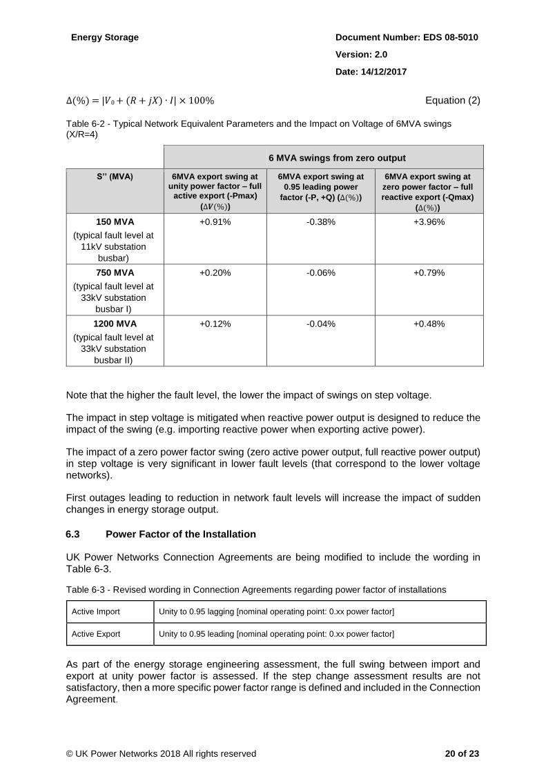
Voltage step change at a location of interest (e.g., point of common coupling for a new connection) can be readily calculated through a method involving network reduction in the point of common coupling, see Figure 6-3.
“Rest of the network”
Figure 6-3 - Reduced Model for Step Voltage Change Calculations
The maximum fault level 𝑆’’ and reactance to resistance ratio X/R at the point of common coupling are required. Indicative values for these (per substation) are available on the LTDS, Table 4. Step voltage change following power swings at that location is then calculated
according to equation (2), where all values are in p.u. 𝑉0 is the voltage at the point of common coupling before the connection (assumed 1 p.u. in the calculations below – Equation 2).
Current 𝐼 is obtained from the apparent power output of the energy storage device. In Table IV are presented voltage step changes caused by 12 MVA power swings with typical parameters for 𝑆’’. X/R is maintained at constant value of 4 throughout all calculations for clarity in results.
( equivalent )
Point of common coupling
Battery import / export
Energy Storage Document Number: EDS 08-5010
Version: 2.0
Date: 14/12/2017
© UK Power Networks 2018 All rights reserved 20 of 23
∆(%) = |𝑉0 + (𝑅 + 𝑗𝑋) ∙ 𝐼| × 100% Equation (2)
Table 6-2 - Typical Network Equivalent Parameters and the Impact on Voltage of 6MVA swings (X/R=4)
6 MVA swings from zero output
S’’ (MVA) 6MVA export swing at unity power factor – full
active export (-Pmax)
(∆𝑽(%))
6MVA export swing at
0.95 leading power
factor (-P, +Q) (∆(%))
6MVA export swing at
zero power factor – full
reactive export (-Qmax)
(∆(%))
150 MVA
(typical fault level at
11kV substation
busbar)
+0.91% -0.38% +3.96%
750 MVA
(typical fault level at
33kV substation
busbar I)
+0.20% -0.06% +0.79%
1200 MVA
(typical fault level at
33kV substation
busbar II)
+0.12% -0.04% +0.48%
Note that the higher the fault level, the lower the impact of swings on step voltage.
The impact in step voltage is mitigated when reactive power output is designed to reduce the impact of the swing (e.g. importing reactive power when exporting active power).
The impact of a zero power factor swing (zero active power output, full reactive power output) in step voltage is very significant in lower fault levels (that correspond to the lower voltage networks).
First outages leading to reduction in network fault levels will increase the impact of sudden changes in energy storage output.
6.3 Power Factor of the Installation
UK Power Networks Connection Agreements are being modified to include the wording in Table 6-3.
Table 6-3 - Revised wording in Connection Agreements regarding power factor of installations
Active Import Unity to 0.95 lagging [nominal operating point: 0.xx power factor]
Active Export Unity to 0.95 leading [nominal operating point: 0.xx power factor]
As part of the energy storage engineering assessment, the full swing between import and export at unity power factor is assessed. If the step change assessment results are not satisfactory, then a more specific power factor range is defined and included in the Connection Agreement.
Energy Storage Document Number: EDS 08-5010
Version: 2.0
Date: 14/12/2017
© UK Power Networks 2018 All rights reserved 21 of 23
UK Power Networks is currently developing an operational P / Q envelope to specify the range the developer needs to comply with and demonstrate during the initial operational notice period. This will provide flexibility to reactive power output once the active power drops below a fraction of the apparent power.
6.4 Security of Supply Regulations (EREC P2/6 Compliance)
UK Power Networks has an obligation to satisfy security of supply standards as set on EREC P2/6. DPC 4.2.1 of the Distribution Code states that 'DNOs shall plan and develop their DNOs Distribution Systems to a standard not less than that set out in DGD Annex 1 Item 5, Engineering Recommendation P2/6 – ‘Security of Supply’ or such other standard of planning as DNO’s may, with the approval of the Authority, adopt from time to time'.
Normal levels of security of supply requirements for different ranges of group demand are indicated in EREC P2/6, Table 1. Consideration of first and second outages is made for selected ranges of group demand.
Whilst a single customer does not constitute a “group” for the purposes of EREC P2/6, the impact of a customer connected to a demand group requiring e.g. second circuit outage capability could be material in determining compliance. This applies also for energy storage applications when assessing import requirements. Each application needs individual consideration in relation to how the customer’s contractual security arrangements impact on the P2/6 assessment. Contractual security arrangements may include automatic demand transfers, operational tripping or utilisation of generation embedded in the customer’s network (export capability, in the case of energy storage) in operating scenarios to be agreed with UK Power Networks.
6.5 Power Quality
UK Power Networks has license obligation to maintain levels of quality of supply to all its customers. A comprehensive background on power quality considerations is provided in UK Power Networks’ planning guidance for disturbing loads5.
All installations must comply with the power quality requirements defined in:
EREC P28 (Planning Limits for Voltage Fluctuations Caused by Industrial, Commercial and Domestic Equipment in the United Kingdom);
EREC P29 (Planning Limits for Voltage Unbalance in the United Kingdom);
EREC G5 (Planning Levels for Harmonic Voltage Distortion and the Connection of NonLinear Equipment to Transmission Systems and Distribution Networks in the United Kingdom).
Upon acceptance of their offer, customers will be expected to demonstrate compliance with the aforementioned Engineering Recommendations before their connection can energise. Data is available via UK Power Networks’ Long Term Development Statement (LTDS) to enable the customer to construct their harmonic impedance model. Also included in the LTDS is maximum demand information and fault levels for network intact conditions. Further to these the Network Parameters report will include an indication of minimum and maximum fault level at the Point of Common Coupling (PCC).
5 http://library.ukpowernetworks.co.uk/library/en/g81/Design_and_Planning/General/EDS+08-
1901+Guidance+for+the+Connection+of+Customer%27s+Disturbing+Loads.pdf (last accessed on 05/12/2017)
Energy Storage Document Number: EDS 08-5010
Version: 2.0
Date: 14/12/2017
© UK Power Networks 2018 All rights reserved 22 of 23
Background harmonic data will be provided at the nearest available measurement point within an agreed timescale. Upon receipt of this the customer will be expected to provide a G5/4-1 compliance report in a timescale that enables its validation, and amendment as required, prior to their energisation date. If the report indicates that planning levels are likely to be exceeded then it may be necessary to include suitable mitigation within their design. Where compatibility limits are exceeded this will certainly be the case. Similarly a P28/P29 compliance report will also be required.
6.6 Additional Requirements for Applications above 50MW and Below 100MW
Energy storage has not yet been classified in the Grid Code. UK Power Networks takes the view that, until further notice, the notes made in this section about generation should also apply for energy storage.
Where a generation site has a registered capacity of 50 MW or more but less than 100MW and is not subject to a Bilateral Agreement with National Grid, then in addition to the Distribution Code, further Grid Code requirements will also apply. These sites are classified as Licence Exempt Embedded Medium Power Stations or LEEMPS.
Customers wishing to connect a generation site to the DNO network within this range of powers should make themselves aware of their obligations under the Grid Code in terms of:
Data provision requirements;
Technical, design and operational criteria;
Compliance, testing and monitoring requirements that the generation site must fulfil before being allowed to connect and generate.
Note that Grid (and Distribution) Code requirements are to be updated shortly to incorporate the changes set by the European Regulation for Requirements for Generators. For more detail refer to Section 6.7.
6.7 European Network Codes – Requirements for Generators (RfG)
A series of European Network Codes are being produced to provide harmonisation across products and markets in Europe. There are 11 Codes in total in three areas – Grid Connections, System Operation and Market Operation. One of these Codes is the Requirements for Generators (RfG).
RfG entered into force on 17 May 2016 and will apply technical requirements to new generators who procure their main plant items after a two year transitional period of implementation at member state level (17 May 2018). RfG uses four incremental type bands (‘A’ to ‘D’) which set a sliding scale of generator technical capabilities to support System Operation. Some of the new technical capabilities were not normally requested at distribution network level in Great Britain (e.g. fault-ride through capability for generation above 1MW of installed capacity).
At the moment only pump-storage is included in the legislation, but other forms of energy storage are expected to be incorporated soon. Customers are advised to make themselves aware of advances in the implementation of RfG into the GB system.
Energy Storage Document Number: EDS 08-5010
Version: 2.0
Date: 14/12/2017
© UK Power Networks 2018 All rights reserved 23 of 23
7 References
7.1 UK Power Networks Standards
EDS 08-0132 Planning Guidance for Disturbing Loads
EDS 08-1901 Guidance for the Connection of Customer's Disturbing Loads
EDS 08-4000 EHV Network Design
EOS 04-1020 Transformer Ratings
7.2 National Standards
ESQCR (2002) Electricity Safety, Quality and Continuity Regulations (2002)
ENA EREC P17 Current Rating Guide for Distribution Cables
ENA EREC P18 Complexity of 132kV Circuits
ENA EREC P2/6 Security of Supply
ENA EREC P27 Current Rating Guide for High Voltage Overhead Lines Operating in the
UK Distribution System
ENA EREC P28 Planning limits for voltage fluctuations caused by industrial, commercial
and domestic equipment
ENA EREC G83
Recommendations for the Connection of Type Tested Small-scale
Embedded Generators (Up to 16A per Phase) in Parallel with Low-Voltage
Distribution Systems
ENA EREC G59 Recommendations for the Connection of Generating Plant to the
Distribution Systems of Licensed Distribution Network Operators
ENA EREC G5/4-1 Planning Levels for Harmonic Voltage Distortion and the Connection of
Non-Linear Equipment to Transmission Systems and Distribution Networks
ENA EREC G100 Technical Requirements for Customer Export Limiting Schemes
The Distribution Code (http://www.dcode.org.uk/)
8 Dependent Documents
This document is referenced in the following documents, any of which may be affected by updates.
EDS 08-5023 Guidelines for Assessing Flexible Distributed Generation Connections
EDS 08-4000 EHV Network Design