Embed Size (px)
Citation preview

The New Zealand Green Building Council
July 2009
Education and Industrial Energy
Calculation Guide
July 2009
This document was prepared on behalf of the NZGBC by Beca with funding from the Energy Efficiency Conservation Authority (EECA).

The New Zealand Green Building Council
July 2009
Acknowledgement
The New Zealand Green Building Council thanks everyone who contributed content, time and effort in the development of the Green Star NZ – Education and Industrial Calculation Guide.
In particular, the New Zealand Green Building Council acknowledges the extraordinary input by members of the Technical Working Group:
Alan Barbour, Beca
Quentin Jackson, Ecubed
Ben Masters, Beca
Mark Ogilvie, Norman Disney Young
Neil Purdie, Aurecon
Scott Smith, Aecom
The New Zealand Green Building Council would also like to acknowledge the patience, time and effort given by all pilot projects using this calculation guide. A special thank you is extended to pilot project team members from Lincolne Scott, Ecubed and Aecom who assisted with the testing and verification of the calculation guide.
The New Zealand Green Building Council also wishes to thank the Energy Efficiency Conservation Authority (EECA) for their generous funding contribution to this project.

The New Zealand Green Building Council
July 2009
Table of Contents
1 Executive Summary ............................................................................................................. 4
2 Energy Calculation Methodology ....................................................................................... 5
2.1 ‘Two-model’ Approach ................................................................................................. 5
2.2 ‘Schedule Method’ Approach ...................................................................................... 5
3 Two-Model Energy Calculation Approach ......................................................................... 7
3.1 Assessable Area .......................................................................................................... 7
3.2 Actual Building Model HVAC and lighting energy use ................................................ 7
3.3 Actual Building Model energy use for other building services ..................................... 7
3.4 Actual Building Model energy benchmark ................................................................... 7
3.5 Reference Building Model HVAC and lighting energy use .......................................... 7
3.6 Reference Building Model energy use for other building services .............................. 8
3.7 Reference Building Model energy benchmark ............................................................ 8
3.8 ENE-1 Compliance ...................................................................................................... 8
3.9 ENE-1 Points allocation ............................................................................................... 8
3.10 On-site energy generation and on-site renewable energy generation ........................ 8
3.11 ENE-2 Points allocation ............................................................................................... 9
4 Actual and Reference Building Model Description ........................................................ 10
5 Schedule Method Approach ............................................................................................. 27
5.1 Performance Benchmarks ......................................................................................... 27
6 Manual calculations for services other than HVAC and lighting .................................. 34
6.1 Actual Building Model ................................................................................................ 34
6.2 Reference Building Model ......................................................................................... 35
7 Example Energy Calculation ............................................................................................ 37
7.1 Actual Building Model energy benchmark ................................................................. 43
7.2 Reference Building Model energy benchmark .......................................................... 43
7.3 ENE-1 Compliance .................................................................................................... 44
7.4 ENE-1 Points allocation ............................................................................................. 44
7.5 Actual Building Model on-site energy generation and on-site renewable energy
generation .................................................................................................................. 44
7.6 ENE-2 Points allocation ............................................................................................. 44
Appendix A – Example Project Registration Proforma ......................................................... 47
Appendix B – Reference Building Model Construction Definition ....................................... 49
Appendix C – Reference Building Model HVAC System Definition ..................................... 51
Appendix D – HVAC Modelling Requirements ........................................................................ 55
Appendix E – Lift Energy Use Calculation .............................................................................. 58
References ................................................................................................................................. 59

Green Star NZ Education & Industrial Energy Calculation Guide
© New Zealand Green Building Council
3 August 2009 // Page 4
1 Executive Summary
This document has been prepared to provide guidance on the energy calculation approach for projects
seeking to be assessed under the Green Star NZ – Education or Industrial rating tools.
Under the Green Star ENE-1 Credit, there are two options with which projects can demonstrate
compliance:
� a ‘Two-model’ energy calculation
OR
� a ‘Schedule Method’ option
Using the Two-model energy calculation approach there are two aspects awarded points under the
ENE-1 and ENE-2 Credits:
� ENE-1 Energy improvement
� ENE-2 Greenhouse gas emissions improvement
The process of carrying out both the two model calculation and the schedule method calculation are
described in this guide.

Green Star NZ Education & Industrial Energy Calculation Guide
© New Zealand Green Building Council
3 August 2009 // Page 5
2 Energy Calculation Methodology
There are two options under ENE-1 of the Green Star NZ – Education and Industrial Tools for the
purposes of benchmarking the energy performance of a building’s design. These are summarised as
follows:
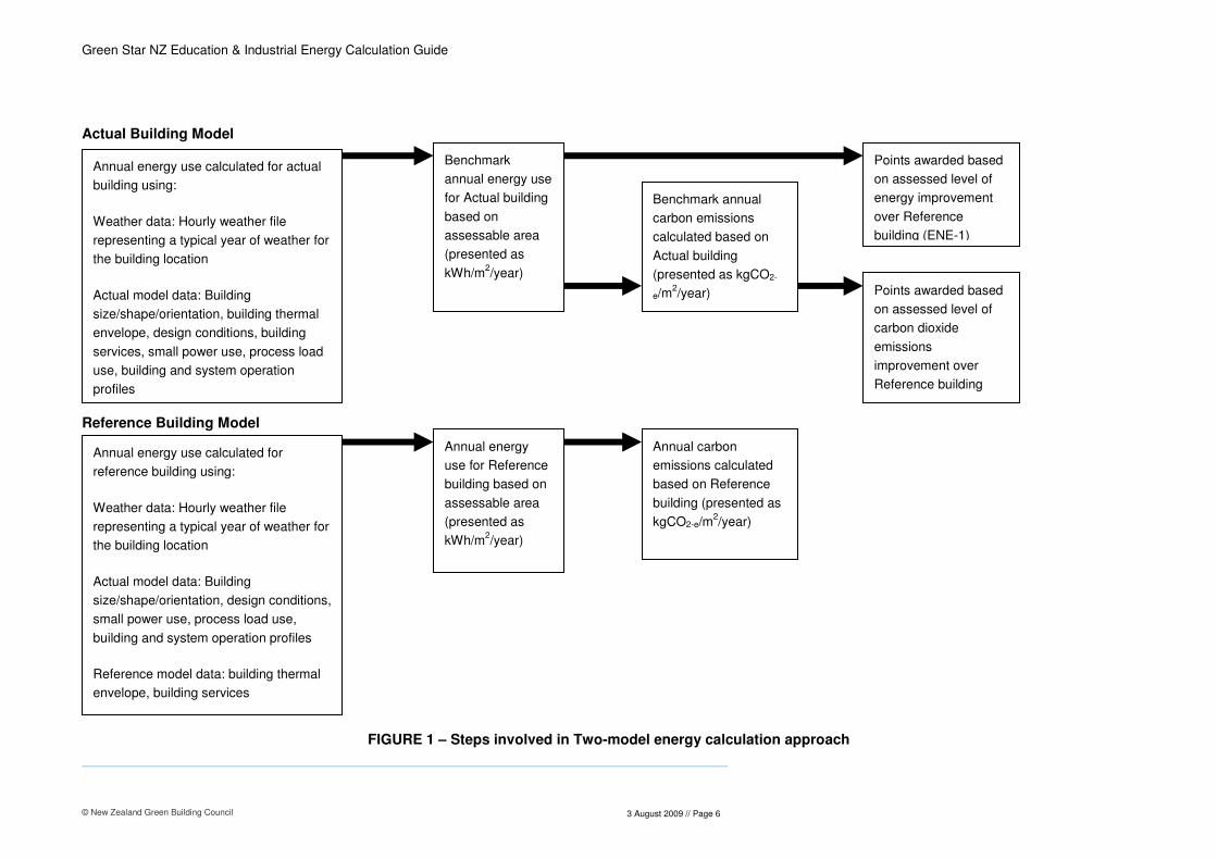
2.1 ‘Two-model’ Approach
The Two-model energy calculation approach compares the improvement between the computer
simulated annual energy target of the Actual (specified) building design over the simulated annual
energy target of a Reference building design. The Reference building generally reflects the project
building’s physical parameters although the building envelope performance and building services
efficiencies are intended to represent current industry ‘Typical Practice’. The flowchart in Figure 1
(over page) outlines the steps involved in carrying out the Two-model calculation.
Using the Two-model energy calculation approach there are two aspects awarded points under the
ENE-1 and ENE-2 Credits:
� ENE-1 Energy improvement
� ENE-2 Greenhouse gas emissions improvement
It is has been the intention of the energy calculation guide to promote the following:
� Building designs that are energy efficient compared to current industry ‘Typical’ Practice
� Building designs and the use of building energy sources that result in low carbon dioxide equivalent
emissions
The guidelines for carrying out the Two-model energy calculation are described in Section 3 of this
guide.
The definition of the Actual and Reference Building Model inputs are described in Section 4 of this
guide.
2.2 ‘Schedule Method’ Approach
For Green Star NZ – Education and Industrial there is also the option of a ‘Schedule Method’ approach
for selected project types that do not wish to undertake energy simulation modelling.
This method can only be used where the project type is able to meet the schedule method
requirements and the installed process power load for the building does not exceed 30W/m2.
Guidelines for carrying out the Schedule Method approach are described in Section 5 of this guide.
The limit for internal design power load is 30W/m2. This includes the sum of tenant small
power and installed process power load in any individual space in the building.
5 points are available under ENE-1 using the ‘Schedule Method’ option.
Green Star NZ Education & Industrial Energy Calculation Guide
© New Zealand Green Building Council
3 August 2009 // Page 6
Actual Building Model
Reference Building Model
FIGURE 1 – Steps involved in Two-model energy calculation approach
Annual energy use calculated for actual
building using:
Weather data: Hourly weather file
representing a typical year of weather for
the building location
Actual model data: Building
size/shape/orientation, building thermal
envelope, design conditions, building
services, small power use, process load
use, building and system operation
profiles
Benchmark
annual energy use
for Actual building
based on
assessable area
(presented as
kWh/m2/year)
Annual energy use calculated for
reference building using:
Weather data: Hourly weather file
representing a typical year of weather for
the building location
Actual model data: Building
size/shape/orientation, design conditions,
small power use, process load use,
building and system operation profiles
Reference model data: building thermal
envelope, building services
Annual energy
use for Reference
building based on
assessable area
(presented as
kWh/m2/year)
Benchmark annual
carbon emissions
calculated based on
Actual building
(presented as kgCO2-
e/m2/year)
Annual carbon
emissions calculated
based on Reference
building (presented as
kgCO2-e/m2/year)
Points awarded based
on assessed level of
carbon dioxide
emissions
improvement over
Reference building
Points awarded based
on assessed level of
energy improvement
over Reference
building (ENE-1)

Green Star NZ Education & Industrial Energy Calculation Guide
© New Zealand Green Building Council
3 August 2009 // Page 7
3 Two-Model Energy Calculation Approach
The steps involved in the Two-model energy calculation approach are as follows:
3.1 Assessable Area
� Input the Usable Floor Area1 (UFA) for Education projects and Gross Floor Area2 (GFA) for
Industrial projects into the Green Star Building Input Sheet of the Green Star spreadsheet
3.2 Actual Building Model HVAC3 and lighting energy use
Calculate the annual HVAC and lighting energy use for the specified building design:
� Use Actual building model input data described in Section 4
� Apply the appropriate operation and usage schedules to all different space types4 within the
building described in Section 4
� Calculate the annual HVAC and lighting energy use (annual small power usage and process load
usage is to be included in the HVAC energy calculation)
� Input annual HVAC and annual lighting energy use into Green Star Energy and GHG Emissions
Calculator – separated for each different energy source e.g. Electricity, natural gas, biomass, coal
etc
3.3 Actual Building Model energy use for other building services
Calculate the annual energy use for building services other than HVAC and lighting:
� Use manual calculation procedures to calculate energy use for other building services in the Actual
building described in Section 6
� Input annual energy use for other building services into Green Star Energy and GHG Emissions
Calculator – separated for each different energy source
3.4 Actual Building Model energy benchmark
� The Green Star spreadsheet will sum together the annual HVAC, lighting and other services annual
energy use to form the Actual Building Model energy benchmark in kWh/m2/year based on the
assessable area
3.5 Reference Building Model HVAC and lighting energy use
Calculate the annual HVAC and lighting energy use for the Reference Building Model:
� Use Reference Building Model input data described in Section 4
� Apply the same operation and usage schedules as used in the Actual Building Model to each
different modelled space types within the building
� Calculate the annual HVAC and lighting energy use (annual small power usage and process load
usage is to be included in the HVAC energy calculation)
1 UFA is defined in the Introduction section to the Education Technical Manual
2 GFA is defined in the Introduction section to the Industrial Technical Manual
3 Heating ventilating and air conditoning designed to control environmental conditions in an internal space
4 Space type in this document refers to internal spaces intended for a different type of use e.g. warehouse,
manufacturing, office, circulation etc
Green Star NZ Education & Industrial Energy Calculation Guide
© New Zealand Green Building Council
3 August 2009 // Page 8
� Input annual HVAC and lighting energy use into Green Star Energy and GHG Emissions Calculator
– Separated into electrical and combustible heating energy demands (combustible heating
demands are given a CO2-e factor of 0.25 kg CO2-e/kWh)
3.6 Reference Building Model energy use for other building services
Calculate the annual energy use for building services other than HVAC and lighting:
� Use manual calculation procedures to calculate energy use for other building services in the
Reference Building Model described in Section 6
� Input annual energy use for other building services into Green Star Energy and GHG Emissions
Calculator – separated for each different energy source
3.7 Reference Building Model energy benchmark
� The Green Star spreadsheet will sum together the annual HVAC, lighting and other services annual
energy use to form the Reference Building Model energy benchmark in kWh/m2/year based on the
assessable area
3.8 ENE-1 Compliance
� In order to comply with ENE-1 the energy benchmark of the Actual Building Model must be less
than the energy benchmark of the Reference Building Model
� The Green Star spreadsheet will indicate whether ENE-1 compliance has been achieved or not
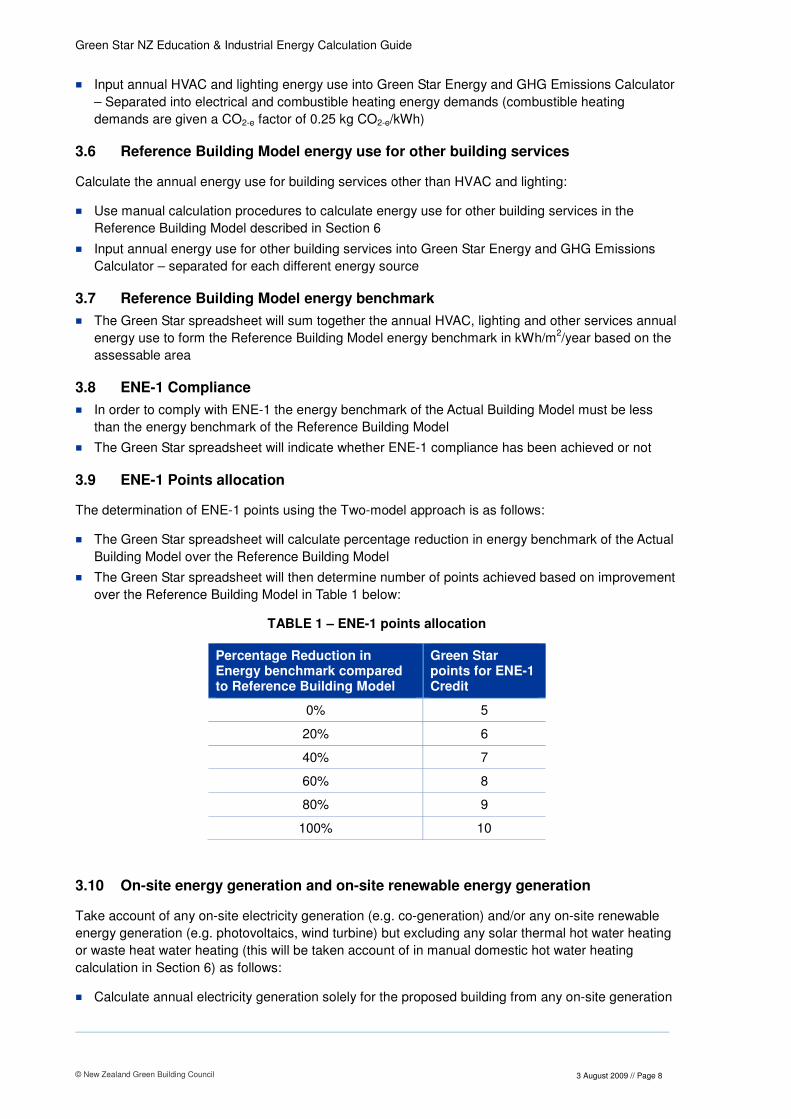
3.9 ENE-1 Points allocation
The determination of ENE-1 points using the Two-model approach is as follows:
� The Green Star spreadsheet will calculate percentage reduction in energy benchmark of the Actual
Building Model over the Reference Building Model
� The Green Star spreadsheet will then determine number of points achieved based on improvement
over the Reference Building Model in Table 1 below:
TABLE 1 – ENE-1 points allocation
Percentage Reduction in Energy benchmark compared to Reference Building Model
Green Star points for ENE-1 Credit
0% 5
20% 6
40% 7
60% 8
80% 9
100% 10
3.10 On-site energy generation and on-site renewable energy generation
Take account of any on-site electricity generation (e.g. co-generation) and/or any on-site renewable
energy generation (e.g. photovoltaics, wind turbine) but excluding any solar thermal hot water heating
or waste heat water heating (this will be taken account of in manual domestic hot water heating
calculation in Section 6) as follows:
� Calculate annual electricity generation solely for the proposed building from any on-site generation

Green Star NZ Education & Industrial Energy Calculation Guide
© New Zealand Green Building Council
3 August 2009 // Page 9
� Calculate annual electricity generation solely for the proposed building from any renewable on-site
generation
� Provide documentation to accompany the energy calculations including at a minimum:
– On-site/on-site renewable energy installed capacity
– On-site/on-site renewable annual energy calculation methodology including all assumptions
� Input annual on-site energy generation into the Green Star spreadsheet energy calculator based on
energy source and separate into combustible and non-combustible generation
� Input annual on-site renewable energy generation into Green Star energy and GHG emissions
calculator
3.11 ENE-2 Points allocation
The determination of ENE-2 points using the Two-model approach is as follows, the Green Star
Spreadsheet will:
� Subtract any contribution from on-site renewable energy generation from the Actual Building Model
energy benchmark
� Then convert the adjusted Actual Building Model energy benchmark to annual carbon dioxide
emissions based on annual kWh/m2 for each energy source and associated emission factor
� Then convert any on-site energy generation to annual carbon dioxide emissions based on annual
kWh/m2 for each energy source and associated emission factor
� Then sum together annual carbon dioxide emissions and any carbon dioxide emissions from on-
site energy generation
� Convert the Reference Building Model energy benchmark to annual carbon dioxide emissions
based on annual kWh/m2 for each energy source
� Then calculate the percentage reduction in carbon dioxide emissions of the Actual Building Model
over the Reference Building Model
� Then determine number of points achieved based on improvement over the Reference Building
Model in Table 2 below:
TABLE 2 – ENE-2 GHG emissions reductions points allocation
Percentage Reduction in CO2-e emissions compared to Reference Building Model
Green Star points for ENE-2 Credit
0% 0
10% 1
20% 2
30% 3
40% 4
50% 5
60% 6
70% 7
80% 8
90% 9
100% 10
Green Star NZ Education & Industrial Energy Calculation Guide
© New Zealand Green Building Council
3 August 2009 // Page 10
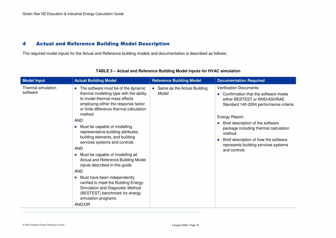
4 Actual and Reference Building Model Description
The required model inputs for the Actual and Reference building models and documentation is described as follows:
TABLE 3 – Actual and Reference Building Model inputs for HVAC simulation
Model Input Actual Building Model Reference Building Model Documentation Required
Thermal simulation software
� The software must be of the dynamic
thermal modelling type with the ability
to model thermal mass effects
employing either the response factor
or finite difference thermal calculation
method
AND
� Must be capable of modelling
representative building attributes,
building elements, and building
services systems and controls
AND
� Must be capable of modelling all
Actual and Reference Building Model
inputs described in this guide
AND
� Must have been independently
verified to meet the Building Energy
Simulation and Diagnostic Method
(BESTEST) benchmark for energy
simulation programs
AND/OR
� Same as the Actual Building
Model Verification Documents:
� Confirmation that the software meets
either BESTEST or ANSI/ASHRAE
Standard 140-2004 performance criteria
Energy Report:
� Brief description of the software
package including thermal calculation
method
� Brief description of how the software
represents building services systems
and controls

Green Star NZ Education & Industrial Energy Calculation Guide
© New Zealand Green Building Council
3 August 2009 // Page 11
Model Input Actual Building Model Reference Building Model Documentation Required
� Must have been independently
verified to meet ANSI/ASHRAE
Standard 140-2004 (Building Thermal
Envelope and Fabric Test Loads)
Weather file � Must be hourly weather data for the
site based on either IWEC source
data created by ASHRAE or NIWA
source data in TMY format (or other
file sanctioned by NZGBC) and
represent an average year’s
conditions for a weather station.
� In the absence of actual weather data
for the site a weather file for a climate
representative of the local climate to
the building must be used.
� Same as the Actual Building
Model
Verification Documents:
� N/A
Energy Report:
� Hourly weather file used
� Weather station location
� If weather station is not site location
justification as to how the weather file
used is representative of the local
climate for the building (to be checked
by NZGBC during registration of the
project for Green Star)
Site orientation � As building design
� Same as the Actual Building
Model
Verification Documents:
� Design or as-installed (where
appropriate) relevant drawings showing
building orientation
Energy Report:
� Details of how the orientation has been
defined within the model
Building overshadowing � Include the affect of overshadowing
from the surrounding environment for
annual energy simulation
� Same as the Actual Building
Model
Verification Documents:
� Design or as-installed (where
appropriate) relevant drawings showing
elements of the surrounding
environment causing overshadowing
Green Star NZ Education & Industrial Energy Calculation Guide
© New Zealand Green Building Council
3 August 2009 // Page 12
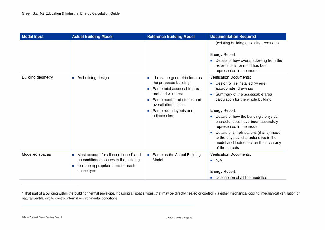
Model Input Actual Building Model Reference Building Model Documentation Required
(existing buildings, existing trees etc)
Energy Report:
� Details of how overshadowing from the
external environment has been
represented in the model
Building geometry � As building design
� The same geometric form as
the proposed building
� Same total assessable area,
roof and wall area
� Same number of stories and
overall dimensions
� Same room layouts and
adjacencies
Verification Documents:
� Design or as-installed (where
appropriate) drawings
� Summary of the assessable area
calculation for the whole building
Energy Report:
� Details of how the building’s physical
characteristics have been accurately
represented in the model
� Details of simplifications (if any) made
to the physical characteristics in the
model and their effect on the accuracy
of the outputs
Modelled spaces � Must account for all conditioned5 and
unconditioned spaces in the building
� Use the appropriate area for each
space type
� Same as the Actual Building
Model
Verification Documents:
� N/A
Energy Report:
� Description of all the modelled
5 That part of a building within the building thermal envelope, including all space types, that may be directly heated or cooled (via either mechanical cooling, mechanical ventilation or
natural ventilation) to control internal environmental conditions

Green Star NZ Education & Industrial Energy Calculation Guide
© New Zealand Green Building Council
3 August 2009 // Page 13
Model Input Actual Building Model Reference Building Model Documentation Required
conditioned and unconditioned spaces
� Description of the modelled usable
area for each modelled space type and
a description of the variance between
the actual measured usable area
Thermal zoning � All conditioned spaces must be zoned
to reflect the system design
performance and layout with regard to
solar orientation
� Same as the Actual Building
Model
Verification Documents:
� N/A
Energy Report:
� Description of design zoning and how
thermal zoning has been defined within
the model
Building thermal envelope � As specified
� Building thermal envelope to
meet equivalent NZBC
minimum thermal requirements
for large buildings1 for all
conditioned spaces only
� Use the NZS:4243 schedule
method to determine R-values
for each associated building
element in the Reference
Building Model
� Where reference glazing R-
value is not listed use 0.18
m2.K/W to represent single
glazing
Verification Documents:
� Design or as-built (where appropriate)
drawings showing building thermal
envelope materials
� Materials schedule or specification
extracts listing material properties or
limits for all thermal envelope materials
� Materials schedule or specification
extracts listing R-values for each
building thermal envelope element
Energy Report:
� Details of how the Actual and
Reference Building Model building
thermal envelope have been modelled
� Description of R-values modelled for

Green Star NZ Education & Industrial Energy Calculation Guide
© New Zealand Green Building Council
3 August 2009 // Page 14
Model Input Actual Building Model Reference Building Model Documentation Required
the Reference Building Model thermal
envelope in line with the NZS:4243
schedule
Building Construction � As specified � Fast thermal response or
‘Lightweight’ construction. See
Appendix B for definition of
each lightweight construction
element
Verification Documents:
� Design or as-built (where appropriate)
drawings showing building structure
materials
Energy Report:
� Details of how the Actual and
Reference Building Model Building
structure has been modelled
External surface Solar Reflectance
� As specified or if unknown use the
same as the Reference Building
Model
� Solar Reflectance = 0.3
(ASHRAE)
� To be assigned to all external
surfaces
Verification Documents:
� Design or as-built Solar Reflectance for
applicable external surfaces
Energy Report:
� Details of how the Actual and
Reference Building Model building solar
reflectance has been modelled
Area of glazing � As building design
� Low height space types (e.g.
offices, circulation): Glazing
window to wall ratio (WWR)
shall equal 50% of the above
grade perimeter external wall
area of conditioned spaces,
and shall be distributed
uniformly across each external
wall where glazing is present
in the Actual Building Model
Verification Documents:
� Design or as-built (where appropriate)
relevant drawings showing all glazing to
the above grade perimeter external wall
area
Energy Report:
� Calculation of the glazing WWR for the
Actual Building Model

Green Star NZ Education & Industrial Energy Calculation Guide
© New Zealand Green Building Council
3 August 2009 // Page 15
Model Input Actual Building Model Reference Building Model Documentation Required
OR
� Tall space types (e.g.
Warehouse, manufacturing
space): Glazing WWR shall
equal that of the Actual
Building Model or 50% of the
above grade perimeter
external wall area of
conditioned spaces, whichever
is smaller, and shall be
distributed uniformly across
each external wall where
glazing is present in the Actual
Building Model
AND
� The WWR calculation should
be based on external wall area
adjacent only to conditioned
spaces
� Details of the glazing WWR modelled in
the Reference Building Model
� Details of the areas of glazing on each
façade for both the Actual and
Reference Building Model

Green Star NZ Education & Industrial Energy Calculation Guide
© New Zealand Green Building Council
3 August 2009 // Page 16
Model Input Actual Building Model Reference Building Model Documentation Required
Glazing G-value6 � As specified � 0.87 Verification Documents:
� Materials schedule or specification
extracts listing glazing G-value
OR
� Materials schedule or specification
extracts listing glazing Shading
Coefficient, Solar Heat Gain Coefficient
or Solar Factor and the resulting glazing
G-value
Energy Report:
� Details of how the glazing G-value has
been represented in the model
Area of skylight � As building design
� Skylight area shall equal that
of the proposed building or 5%
of the gross roof area,
whichever is smaller
(ASHRAE)
Verification Documents:
� Design or as-built (where appropriate)
relevant drawings showing total area of
skylight
Energy Report:
� Calculation of the skylight area as a
percentage of the gross roof area for
the Actual Building Model
� Details of the skylight area modelled in
the Reference Building Model
Skylight G-value � As specified � 0.87 Verification Documents:
6 The G-value is defined as the sum of the direct solar transmittance and the heat transferred by radiation and convection into the space (CIBSE). This is also known as the solar factor or solar heat gain coefficient

Green Star NZ Education & Industrial Energy Calculation Guide
© New Zealand Green Building Council
3 August 2009 // Page 17
Model Input Actual Building Model Reference Building Model Documentation Required
� Materials schedule or specification
extracts listing skylight G-value
OR
� Materials schedule or specification
extracts listing skylight Shading
Coefficient, Solar Heat Gain Coefficient
or Solar Factor and the resulting
skylight G-value
Energy Report:
� Details of how the skylight G-value has
been represented in the model
Fixed external solar shading device7
� As building design � None Verification Documents:
� Design or as-installed (where
appropriate) relevant drawings showing
all fixed external shading device
Energy Report:
� Details of how the fixed external
shading device have been represented
in the Actual Building Model
Manually controlled internal shading device e.g. curtains, blinds etc
� Not modelled unless daylight
harvesting control taken account of in
Actual Building Model
� Not modelled N/A
7 This includes any fixed building element providing solar shading e.g. louvers, roof overhangs, and balconies etc

Green Star NZ Education & Industrial Energy Calculation Guide
© New Zealand Green Building Council
3 August 2009 // Page 18
Model Input Actual Building Model Reference Building Model Documentation Required
Manually controlled external shading device e.g. solar control blinds, external louvers/screens
� As specified
� Controlled to be in closed position
when incident solar radiation
measured at the building element to
be shaded > 150 W/m2 and open
when incident solar radiation < 150
W/m2
� Not modelled Verification Documents:
� Design or as-installed (where
appropriate) relevant drawings showing
all manually controlled external shading
device
� Specification extracts listing control
description for manually controlled
shading device
Energy Report:
� Details of how the manually controlled
shading device have been represented
in the Actual Building Model
� Description of how the manually
controlled shading device is controlled
in the Actual Building Model
Automatically controlled shading device e.g. solar control blinds, external louvres
� As specified
� Controlled to be in open/closed
position determined by incident solar
radiation as specified.
� Not modelled Verification Documents:
� Design or as-installed (where
appropriate) relevant drawings showing
all automatically controlled external
shading device
� Specification extracts listing control
description for automatically controlled
shading devices
Energy Report:
� Details of how the automatically
controlled shading device have been
represented in the Actual Building
Model

Green Star NZ Education & Industrial Energy Calculation Guide
© New Zealand Green Building Council
3 August 2009 // Page 19
Model Input Actual Building Model Reference Building Model Documentation Required
� Description of how the automatically
controlled shading device is controlled
in the Actual Building Model
Design space temperature and humidity conditions
� As specified for each space type in
the building, including specified
control range and dead-bands
� Same as the Actual Building
Model Verification Documents:
� Specification extracts listing design
space temperature and humidity
conditions for each conditioned space
type in the building
Energy Report:
� Description of design space
temperatures and humidity for each
conditioned space type in both the
Actual and Reference Building Model
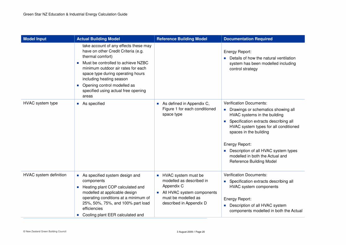
Manually controlled natural ventilation openings
� As specified
� Must be controlled to achieve NZBC
minimum outdoor air rates for each
space type during operating hours
including heating season
� Modelled to control using actual free
opening areas
� Opening control must take into
account control lag through increase
in control deadband; 2°C increase
above design cooling temperature
and 2°C below design heating
temperature
� Not modelled Verification Documents:
� Specification extracts listing opening
sizes and control mechanism
Energy Report:
� Details of how the natural ventilation
system has been modelled including
control strategy
Automatically controlled natural ventilation openings
� As specified. Energy saving
controls specified (e.g. night purge)
can be included but the model must
� Not modelled Verification Documents:
� Specification extracts listing opening
sizes and control mechanism
Green Star NZ Education & Industrial Energy Calculation Guide
© New Zealand Green Building Council
3 August 2009 // Page 20
Model Input Actual Building Model Reference Building Model Documentation Required
take account of any effects these may
have on other Credit Criteria (e.g.
thermal comfort)
� Must be controlled to achieve NZBC
minimum outdoor air rates for each
space type during operating hours
including heating season
� Opening control modelled as
specified using actual free opening
areas
Energy Report:
� Details of how the natural ventilation
system has been modelled including
control strategy
HVAC system type � As specified � As defined in Appendix C,
Figure 1 for each conditioned
space type
Verification Documents:
� Drawings or schematics showing all
HVAC systems in the building
� Specification extracts describing all
HVAC system types for all conditioned
spaces in the building
Energy Report:
� Description of all HVAC system types
modelled in both the Actual and
Reference Building Model
HVAC system definition � As specified system design and
components
� Heating plant COP calculated and
modelled at applicable design
operating conditions at a minimum of
25%, 50%, 75%, and 100% part load
efficiencies
� Cooling plant EER calculated and
� HVAC system must be
modelled as described in
Appendix C
� All HVAC system components
must be modelled as
described in Appendix D
Verification Documents:
� Specification extracts describing all
HVAC system components
Energy Report:
� Description of all HVAC system
components modelled in both the Actual

Green Star NZ Education & Industrial Energy Calculation Guide
© New Zealand Green Building Council
3 August 2009 // Page 21
Model Input Actual Building Model Reference Building Model Documentation Required
modelled at applicable design
operating conditions at a minimum of
25%, 50%, 75%, 100% part load
efficiencies
� All HVAC components must be
modelled as described in Appendix D
and Reference Building Model. At a
minimum the requirements described in
Appendix D
Minimum outdoor air rate � As specified and claimed in IEQ-2
Ventilation Rate Credit for each space
type
� Outdoor air rate for each space type
must be achieved during operating
hours
� NZBC minimum for each
space type
� If space type not covered
under NZBC use the same
outdoor air rate as in the
Actual Building Model
Verification Documents:
� IEQ-2 Credit submission
Energy Report:
� N/A
Heating and cooling plant capacity
� As specified � Sized for the Reference
Building Model
Verification Documents:
� Specification extracts describing the
specified heating and cooling plant
capacities
Energy Report:
� Description of the heating and cooling
plant capacities modelled for the Actual
and Reference Building Model
Piping/duct heat losses/gains
� 5% � 5% Energy Report:
� Description of piping/duct heat
losses/gains modelled for both the
Actual and Reference Building Model
HVAC plant operating schedule
� As specified � Same as the Actual Building
Model
Verification Documents:
� Specification extracts describing the
proposed HVAC plant operating
schedule

Green Star NZ Education & Industrial Energy Calculation Guide
© New Zealand Green Building Council
3 August 2009 // Page 22
Model Input Actual Building Model Reference Building Model Documentation Required
Energy Report:
� Description of the modelled HVAC plant
operating schedule for all conditioned
space types for both the Actual and
Reference Building Model
Heating plant energy source
� As specified � 0.25kg CO2-e/kWh/year carbon
emission factor Verification Documents:
� Specification extracts describing the
heating plant energy source
Energy Report:
� Description of the heating plant energy
source for both the Actual and
Reference Building Model
Cooling plant energy source
� As specified � Grid supplied electricity Verification Documents:
� Specification extracts describing the
cooling plant energy source
Lighting power density � As specified for each space type � For each space type use
lighting power density limits
defined in NZS:4243.2 Table 1
� For any space types not listed
in NZS:4243.2 Table 1 use
lighting power density
calculation (NZS:4243.2
Section 3.4.9) with reference
to AS/NZS 1680.2 maintained
illuminance levels to determine
lighting power density limit
� If the exact space type isn't
listed in AS/NZS 1680.2, select
Verification Documents:
� As specified design lighting levels which
will be provided for each space type
� Luminaire schedule
� Reflected ceiling plans clearly showing
each typical lighting layout and the
types of luminaires used
Energy Report:
� Calculations showing the modelled
lighting power density for each space
type in the Actual and Reference

Green Star NZ Education & Industrial Energy Calculation Guide
© New Zealand Green Building Council
3 August 2009 // Page 23
Model Input Actual Building Model Reference Building Model Documentation Required
most appropriate space type
and associated maintained
illuminance level
Building Model
� Justification for selection of appropriate
space types and associated maintained
illuminance level for any that are not
listed in AS/NZS 1680.2
Lighting schedule � As specified and taking account of
daylight harvesting control where
specified
� Daylight harvesting control must take
into account the operation of any
internal blinds and affect of resulting
lighting levels
� Same as the Actual Building
Model but excluding any
daylight harvesting control
Verification Documents:
� Specification extracts describing the
proposed lighting operating schedule
� Specification extracts describing any
daylight harvesting control and control
settings
Energy Report:
� Description of the modelled lighting
operating schedule for both the Actual
and Reference Building Model
� Description of how the effect of any
daylight harvesting control has been
incorporated into the energy calculation
� Justification for selection of appropriate
lighting power densities for space types
that are not listed.
Small power density � As specified for each space type � Same as the Actual Building
Model Verification Documents:
� Schedule or specification documents
describing the installed small power
density in each space type
Energy Report:
� Description of the mean small power
density modelled for each space type in

Green Star NZ Education & Industrial Energy Calculation Guide
© New Zealand Green Building Council
3 August 2009 // Page 24
Model Input Actual Building Model Reference Building Model Documentation Required
both the Actual and Reference Building
Model
Small power schedule � As specified � Same as the Actual Building
Model Verification Documents:
� Specification extracts describing the
designed small power operating
schedule for each space type
Energy Report:
� Description of the modelled small power
operating schedule for each space type
in both the Actual and Reference
Building Model
Process load density � As specified for each space type � Same as the Actual Building
Model Verification Documents:
� Schedule or specification documents
describing the installed process load
density in each space type
Energy Report:
� Description of the mean process load
density modelled for each space type in
both the Actual and Reference Building
Model
Process load schedule � As specified � Same as the Actual Building
Model Verification Documents:
� Specification extracts describing the
designed process load operating
schedule for each space type
Energy Report:
� Description of the modelled process

Green Star NZ Education & Industrial Energy Calculation Guide
© New Zealand Green Building Council
3 August 2009 // Page 25
Model Input Actual Building Model Reference Building Model Documentation Required
load operating schedule for all spaces
in both the Actual and Reference
Building Model
Occupancy density � As specified for each space type � Same as the Actual Building
Model Verification Documents:
� Schedule or specification documents
describing the design occupancy
density for each space type
Energy Report:
� Description of the intended activities
and associated occupant sensible and
latent gains for each space type
� Occupancy density modelled for each
space type in both the Actual and
Reference Building Model
Occupancy schedule � As specified � Same as the Actual Building
Model Verification Documents:
� Specification extracts describing the
designed occupancy schedule for each
space type
Energy Report:
� Description of the modelled occupancy
schedule for each space type in both
the Actual and Reference Building
Model
Infiltration � Infiltration must be modelled to reflect
façade design specification for
different space types. These would
vary based on space type e.g. clean
rooms and freezers are likely to have
� 0.5 ACH 24 hours/day/7 days
a week for all spaces
Verification Documents:
� Design or as-installed (where
appropriate) relevant drawings showing
façade design specification for each

Green Star NZ Education & Industrial Energy Calculation Guide
© New Zealand Green Building Council
3 August 2009 // Page 26
Model Input Actual Building Model Reference Building Model Documentation Required
highly controlled infiltration rates
compared to warehouses
� External openings larger than 2m2
(typical door) must be explicitly
modelled with applicable operation
profile
space type
Energy Report:
� Description of the infiltration rate
modelled for each space type in both
the Actual and Reference Building
Model
� Description of how any significant
external openings have been modelled
� Description of how any measures to
reduce infiltration effect just as door
curtains and heating systems have
been modelled

Green Star NZ Education & Industrial Energy Calculation Guide
© New Zealand Green Building Council
3 August 2009 // Page 27
5 Schedule Method Approach
5.1 Performance Benchmarks
In order to meet the alternative Schedule Method option under ENE-1 each building element must meet the performance benchmarks described in Table 3 below:
TABLE 4 – Performance benchmarks required for ENE-1 Schedule Method approach
Item Number
Building Element
Performance Benchmark Documentation Required Comment
1 Building thermal envelope
� Building Thermal Envelope to meet
equivalent NZBC minimum
requirements for large buildings for all
conditioned spaces
� Where proposed WWR ≤ 50% use the
NZS:4243 schedule method to
determine minimum R-values required
� Where proposed WWR > 50% use the
NZS:4243 calculation method to
determine minimum R-values required
Verification Documents:
� Design or as-installed (where
appropriate) relevant drawings
showing building thermal envelope
materials specified
� Materials schedule or specification
extracts listing R-values for each
building thermal envelope element
Schedule Method report:
� Description of how the building
complies with the NZS:4243 schedule
method
Refer to NZS:4243 Energy Efficiency – Large Buildings, Part 1: Building Thermal Envelope
2 Glazing G-value � ≤ 0.87 Verification Documents:
� Materials schedule or specification
extracts listing glazing G-value
OR
� Materials schedule or specification
extracts listing glazing Shading
Coefficient, Solar Heat Gain
Coefficient or Solar factor and the

Green Star NZ Education & Industrial Energy Calculation Guide
© New Zealand Green Building Council
3 August 2009 // Page 28
Item Number
Building Element
Performance Benchmark Documentation Required Comment
resulting glazing G-value
Schedule Method report:
� Brief summary of glazing G-values
specified
3 Skylight area � ≤ 5% gross roof area Verification Documents:
� Design or as-installed (where
appropriate) relevant drawings
showing all skylight area
Schedule Method report:
� Calculation of the skylight area as a
percentage of the gross roof area
4 Skylight G-value � ≤ 0.87 Verification Documents:
� Materials schedule or specification
extracts listing skylight G-value
OR
� Materials schedule or specification
extracts listing skylight Shading
Coefficient, Solar Heat Gain
Coefficient or Solar factor and the
resulting skylight G-value
Schedule Method report:
� Brief summary of skylight G-values
specified
5 HVAC system � Each applicable HVAC system
component must meet Reference
Building Model HVAC system
Verification Documents:
� Specification extracts describing all
HVAC system components
Green Star NZ Education & Industrial Energy Calculation Guide
© New Zealand Green Building Council
3 August 2009 // Page 29
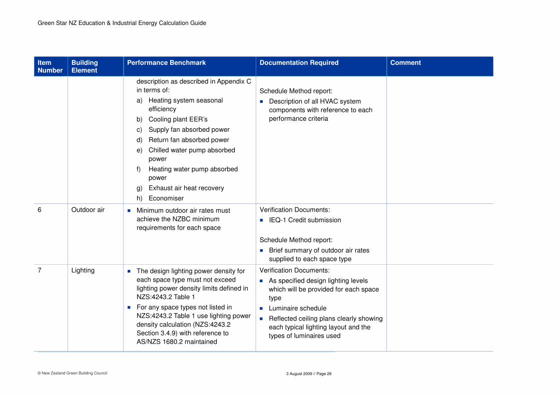
Item Number
Building Element
Performance Benchmark Documentation Required Comment
description as described in Appendix C
in terms of:
a) Heating system seasonal
efficiency
b) Cooling plant EER’s
c) Supply fan absorbed power
d) Return fan absorbed power
e) Chilled water pump absorbed
power
f) Heating water pump absorbed
power
g) Exhaust air heat recovery
h) Economiser
Schedule Method report:
� Description of all HVAC system
components with reference to each
performance criteria
6 Outdoor air � Minimum outdoor air rates must
achieve the NZBC minimum
requirements for each space
Verification Documents:
� IEQ-1 Credit submission
Schedule Method report:
� Brief summary of outdoor air rates
supplied to each space type
7 Lighting � The design lighting power density for
each space type must not exceed
lighting power density limits defined in
NZS:4243.2 Table 1
� For any space types not listed in
NZS:4243.2 Table 1 use lighting power
density calculation (NZS:4243.2
Section 3.4.9) with reference to
AS/NZS 1680.2 maintained
Verification Documents:
� As specified design lighting levels
which will be provided for each space
type
� Luminaire schedule
� Reflected ceiling plans clearly showing
each typical lighting layout and the
types of luminaires used

Green Star NZ Education & Industrial Energy Calculation Guide
© New Zealand Green Building Council
3 August 2009 // Page 30
Item Number
Building Element
Performance Benchmark Documentation Required Comment
illuminance levels to determine lighting
power density limit
� If the exact space type isn't listed in
AS/NZS 1680.2, select most
appropriate space type and associated
maintained illuminance level
Schedule Method report:
� Calculations showing the lighting
power density for each space type
� Justification for selection of
appropriate space types and
associated maintained illuminance
level for any that are not listed in
AS/NZS 1680.2
8 Domestic hot water heating system thermal efficiency
� ≥ 80% thermal efficiency Verification Documents:
� Schedule or specification extract
describing the domestic hot water
heating system type and thermal
efficiency
Schedule Method report:
� Brief description of DHW heating
system and the thermal efficiency
9 Domestic hot water sanitary fittings
� A maximum of 9 litres/min for showers
� A maximum of 6 litres/min for hot water
taps
Verification Documents:
� Schedule or specification documents
describing the flow rates for specified
shower and hot water tap fittings
Schedule Method report:
� Brief description of sanitary fittings
specified and their flow rates or Wat-1
Credit documentation
10 Domestic hot water Pipe insulation
� All domestic hot water pipework must
be insulated to provide a total R-value
Verification Documents:
� Schedule or specification extract
describing the level of insulation

Green Star NZ Education & Industrial Energy Calculation Guide
© New Zealand Green Building Council
3 August 2009 // Page 31
Item Number
Building Element
Performance Benchmark Documentation Required Comment
≥ 0.3m2.K/W required for domestic hot water
pipework
Schedule Method report:
� Brief description of DHW pipework
insulation specified and R-value
11 Chilled water flow and return pipework insulation
� Minimum total R-value for cooling
system ≥ 65 kWr capacity but ≤ 250
kWr capacity:
a) Located internally = 0.9
b) Located within a wall space, an
enclosed sub-floor area or an
enclosed roof space = 1.0
c) Located outside the building or in
an unenclosed sub-floor area or an
unenclosed roof space = 1.1
� Minimum total R-value for cooling
system > 250 kWr capacity:
a) Located internally = 1.2
b) Located within a wall space, an
enclosed sub-floor area or an
enclosed roof space = 1.3
c) Located outside the building or in
an unenclosed sub-floor area or an
unenclosed roof space = 1.4
Verification Documents:
� Schedule or specification extract
describing the level of insulation
required for chilled water pipework
Schedule Method report:
� Brief description of chilled water
pipework insulation specified and R-
value

Green Star NZ Education & Industrial Energy Calculation Guide
© New Zealand Green Building Council
3 August 2009 // Page 32
Item Number
Building Element
Performance Benchmark Documentation Required Comment
12 Heating water flow and return pipework insulation
� Minimum total R-value for heating
system ≤ 65 kW capacity:
a) Located internally = 0.2
b) Located within a wall space, an
enclosed sub-floor area or an
enclosed roof space = 0.45
c) Located outside the building or in
an unenclosed sub-floor area or an
unenclosed roof space = 0.6
� Minimum total R-value for heating
system > 65 kW capacity:
a) Located internally = 0.6
b) Located within a wall space, an
enclosed sub-floor area or an
enclosed roof space = 0.7
c) Located outside the building or in
an unenclosed sub-floor area or an
unenclosed roof space = 0.8
Verification Documents:
� Schedule or specification extract
describing the level of insulation
required for heating water pipework
Schedule Method report:
� Brief description of heating water
pipework insulation specified and R-
value
13 Ductwork insulation
� Minimum total R-value for ductwork
and fittings for systems ≤ 65 kWr
cooling capacity and 65 kW heating
capacity:
a) Evaporative cooling system = 0.6
b) Heating-only system or
refrigerated cooling system = 1.0
c) Combined heating and refrigerated
cooling system = 1.5
d) Fittings for each system type = 0.4
Verification Documents:
� Specification extracts describing the
levels of insulation for ductwork
serving air conditioned spaces
Schedule Method report:
� Brief description of all ductwork
insulation specified and R-value

Green Star NZ Education & Industrial Energy Calculation Guide
© New Zealand Green Building Council
3 August 2009 // Page 33
Item Number
Building Element
Performance Benchmark Documentation Required Comment
� Minimum total R-value for ductwork
and fittings for systems > 65 kWr
cooling capacity and 65 kW heating
capacity:
a) Evaporative cooling system within
a conditioned space = Nil
b) Evaporative cooling system in all
other locations = 0.9
c) Heating system or refrigerated
cooling system within a
conditioned space = 1.3
d) Heating system or refrigerated
cooling system in all other
locations = 1.8

Green Star NZ Education & Industrial Energy Calculation Guide
© New Zealand Green Building Council
3 August 2009 // Page 34
6 Manual calculations for services other than HVAC and
lighting
6.1 Actual Building Model
6.1.1 Mechanical ventilation
� Calculate annual energy use for mechanical ventilation not already accounted for in the energy
model e.g. toilet extract
� Use specified fans, fan total efficiencies (product of fan and motor efficiency), flow rates and total
pressure (static and dynamic)
� Use specified mechanical extract operation schedules
� Provide verification documentation:
– Design or as-installed (where appropriate) relevant drawings or schematics showing all
mechanical extract
– Schedule or specification extract describing all mechanical extract
– Specification extracts describing the proposed mechanical extract operating schedule
� Include in energy report:
– Manual calculation methodology for mechanical extract
6.1.2 Domestic hot water
� Calculate annual energy use for domestic hot water use e.g. Bathrooms and Kitchenettes, wash
hand basins, showers etc with reference to water consumption calculated in Wat-1 Credit. Do not
include any hot water required for any Education or Industrial process
� Use specified domestic hot water generation system efficiency
� Use actual domestic hot water heating energy source
� Take account of any waste heat recovery
� Take account of any solar thermal hot water generation
� Provide verification documentation:
– Schedule or specification extract describing domestic hot water generation system
� Include in energy report:
– Manual calculation methodology for domestic hot water
– Manual calculation methodology for any waste heat recovery water heating
– Manual calculation methodology for any solar thermal hot water generation
6.1.3 Hydraulics pumps
� Calculate annual energy use for all hydraulics pumps not already accounted for in the energy
model. Do not include any pump energy required for any industrial process.
� Use specified pumps, pump efficiencies, flow rates and total pump head
� Use specified operation schedules
� Provide verification documentation:
– Design or as-installed (where appropriate) relevant drawings or schematics showing all
hydraulics pumps
– Schedule or specification extract describing all hydraulics pumps
– Specification extracts describing the proposed mechanical extract operating schedule
� Include in energy report:
– Manual calculation methodology for hydraulics pump energy
Green Star NZ Education & Industrial Energy Calculation Guide
© New Zealand Green Building Council
3 August 2009 // Page 35
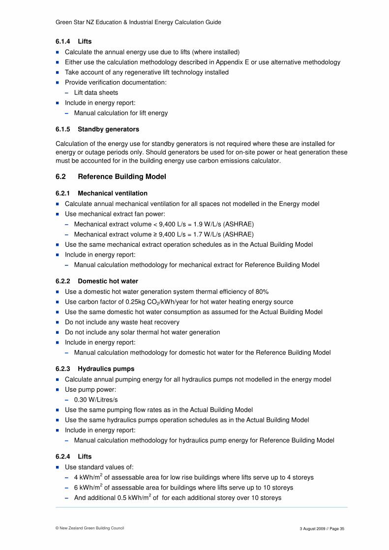
6.1.4 Lifts
� Calculate the annual energy use due to lifts (where installed)
� Either use the calculation methodology described in Appendix E or use alternative methodology
� Take account of any regenerative lift technology installed
� Provide verification documentation:
– Lift data sheets
� Include in energy report:
– Manual calculation for lift energy
6.1.5 Standby generators
Calculation of the energy use for standby generators is not required where these are installed for
energy or outage periods only. Should generators be used for on-site power or heat generation these
must be accounted for in the building energy use carbon emissions calculator.
6.2 Reference Building Model
6.2.1 Mechanical ventilation
� Calculate annual mechanical ventilation for all spaces not modelled in the Energy model
� Use mechanical extract fan power:
– Mechanical extract volume < 9,400 L/s = 1.9 W/L/s (ASHRAE)
– Mechanical extract volume ≥ 9,400 L/s = 1.7 W/L/s (ASHRAE)
� Use the same mechanical extract operation schedules as in the Actual Building Model
� Include in energy report:
– Manual calculation methodology for mechanical extract for Reference Building Model
6.2.2 Domestic hot water
� Use a domestic hot water generation system thermal efficiency of 80%
� Use carbon factor of 0.25kg CO2/kWh/year for hot water heating energy source
� Use the same domestic hot water consumption as assumed for the Actual Building Model
� Do not include any waste heat recovery
� Do not include any solar thermal hot water generation
� Include in energy report:
– Manual calculation methodology for domestic hot water for the Reference Building Model
6.2.3 Hydraulics pumps
� Calculate annual pumping energy for all hydraulics pumps not modelled in the energy model
� Use pump power:
– 0.30 W/Litres/s
� Use the same pumping flow rates as in the Actual Building Model
� Use the same hydraulics pumps operation schedules as in the Actual Building Model
� Include in energy report:
– Manual calculation methodology for hydraulics pump energy for Reference Building Model
6.2.4 Lifts
� Use standard values of:
– 4 kWh/m2 of assessable area for low rise buildings where lifts serve up to 4 storeys
– 6 kWh/m2 of assessable area for buildings where lifts serve up to 10 storeys
– And additional 0.5 kWh/m2 of for each additional storey over 10 storeys

Green Star NZ Education & Industrial Energy Calculation Guide
© New Zealand Green Building Council
3 August 2009 // Page 36
6.2.5 Standby generators
Calculation of the energy use for standby generators is not required.
Green Star NZ Education & Industrial Energy Calculation Guide
© New Zealand Green Building Council
3 August 2009 // Page 37
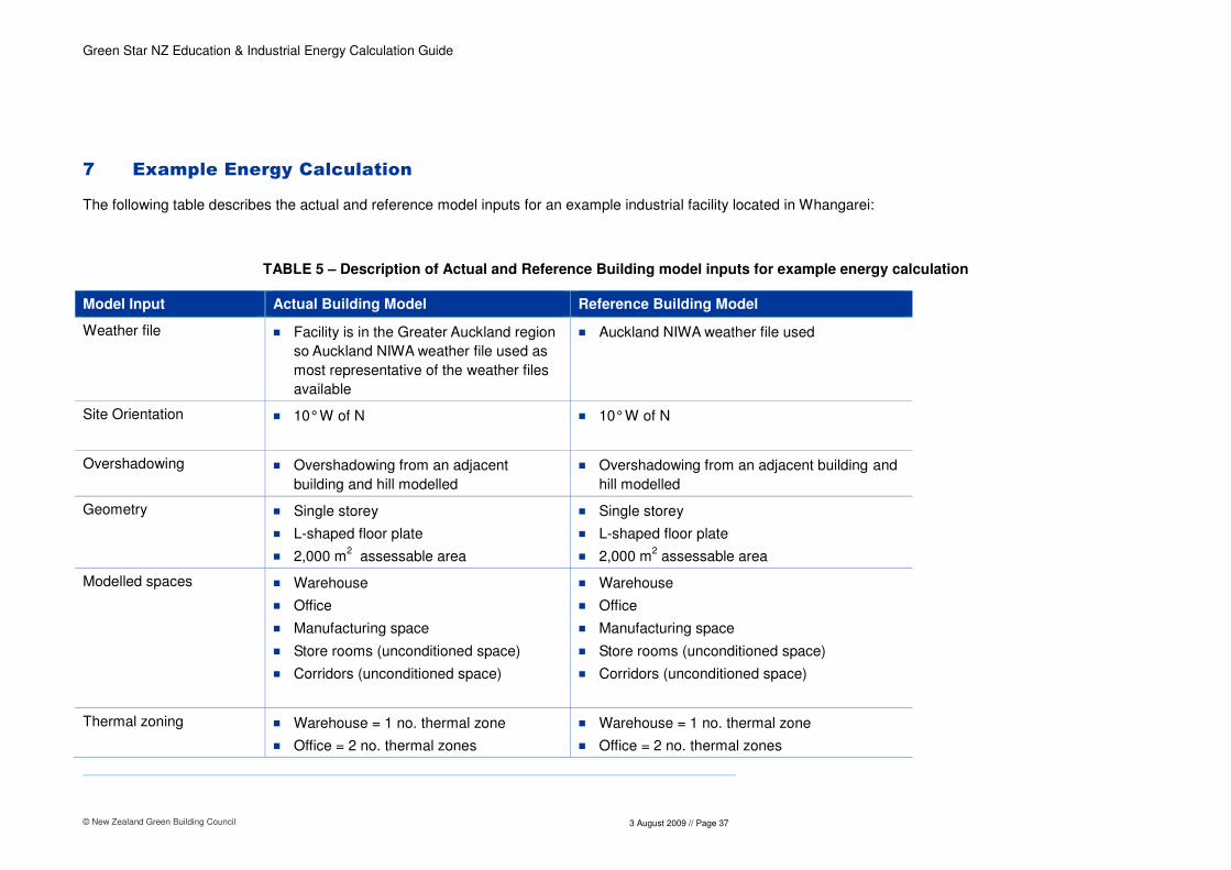
7 Example Energy Calculation
The following table describes the actual and reference model inputs for an example industrial facility located in Whangarei:
TABLE 5 – Description of Actual and Reference Building model inputs for example energy calculation
Model Input Actual Building Model Reference Building Model
Weather file � Facility is in the Greater Auckland region
so Auckland NIWA weather file used as
most representative of the weather files
available
� Auckland NIWA weather file used
Site Orientation � 10° W of N
� 10° W of N
Overshadowing � Overshadowing from an adjacent
building and hill modelled
� Overshadowing from an adjacent building and
hill modelled
Geometry � Single storey
� L-shaped floor plate
� 2,000 m2 assessable area
� Single storey
� L-shaped floor plate
� 2,000 m2 assessable area
Modelled spaces � Warehouse
� Office
� Manufacturing space
� Store rooms (unconditioned space)
� Corridors (unconditioned space)
� Warehouse
� Office
� Manufacturing space
� Store rooms (unconditioned space)
� Corridors (unconditioned space)
Thermal zoning � Warehouse = 1 no. thermal zone
� Office = 2 no. thermal zones
� Warehouse = 1 no. thermal zone
� Office = 2 no. thermal zones

Green Star NZ Education & Industrial Energy Calculation Guide
© New Zealand Green Building Council
3 August 2009 // Page 38
Model Input Actual Building Model Reference Building Model
� Manufacturing space = 1 no. thermal
zone
� Manufacturing space = 1 no. thermal zone
Building thermal envelope � Warehouse uninsulated
� Office:
- Single glazed
- Wall insulation
- Roof insulation
� Manufacturing space uninsulated
� Store rooms uninsulated
� Corridors uninsulated
� Warehouse thermal envelope meets NZS:4243
schedule method as a conditioned space
� Office thermal envelope meets NZS:4243
schedule method as a conditioned space
� Manufacturing space thermal envelope meets
NZS:4243 schedule method as a conditioned
space
� Store rooms uninsulated as not a conditioned
space
� Corridors uninsulated as not a conditioned
space
Building Construction ’Heavyweight’ construction for all space
types:
� Concrete block external walls
� Concrete block partition walls
� ‘Lightweight’ construction as per Appendix B
for all space types
External surface Solar Reflectance
� Roof = 0.7
� External walls = 0.3
� Roof = 0.3
� External walls = 0.3
Area of glazing � Warehouse: 20% WWR
� Office: 30% WWR
� Manufacturing space:5%
� Store rooms: 0% WWR
� Corridors: 10% WWR
� Warehouse (Tall space type): 20% WWR
distributed uniformly across each external wall
where glazing is present in the Actual Building
Model
� Office (Low height space type): 50% WWR
distributed uniformly across each external wall
where glazing is present in the Actual Building
Model
� Manufacturing space (Tall space type): 5%
WWR distributed uniformly across each

Green Star NZ Education & Industrial Energy Calculation Guide
© New Zealand Green Building Council
3 August 2009 // Page 39
Model Input Actual Building Model Reference Building Model
external wall where glazing is present in the
Actual Building Model
� Store rooms: 0% WWR
� Corridors: 0% WWR (As unconditioned space)
Glazing G-value � 0.5
� 0.87
Area of skylight � 8% of the gross roof area � 5% of the gross roof area
Skylight G-value � 0.5 � 0.87
Fixed external solar shading device
� Fixed external horizontal solar shading to
North facade � Not modelled
Manually controlled internal shading device e.g. curtains, blinds etc
� Not modelled � Not modelled
Manually controlled external shading device e.g. solar control blinds, external louvers/screens
� Not specified � Not modelled
Automatically controlled shading device e.g. solar control blinds, external louvres
� No automatically controlled shading
device
� Not modelled
Design temperature conditions
� Warehouse = Heating only 16°C
� Office = 21°C/22°C +/- 1.5°C
� Manufacturing space = Cooling only
22°C
� Store room = Unconditioned space
� Corridors = Unconditioned space
� Warehouse = Heating only 16°C
� Office = 21°C/22°C +/- 1.5°C
� Manufacturing space = Cooling only 22°C
� Store room = Unconditioned space
� Corridors = Unconditioned space

Green Star NZ Education & Industrial Energy Calculation Guide
© New Zealand Green Building Council
3 August 2009 // Page 40
Model Input Actual Building Model Reference Building Model
Manually controlled natural ventilation openings
� Warehouse = High level ventilation
louvers
� Office = None specified
� Manufacturing space = None specified
� Not modelled
Automatically controlled natural ventilation openings
� None specified � Not modelled
HVAC system type � Warehouse = Electric radiant heating
� Office = Fan coil units (Chiller/heat
pump)
� Manufacturing space = CAV system
(Chiller/heat pump)
� Warehouse = CAV multizone system
� Office = CAV multizone system
� Manufacturing space = CAV multizone system
HVAC system definition � Electric radiant heating = 95% thermal
efficiency
� Air source heat pump = 200 kW
� Air source chiller = 300 kW
� 200kWr air source heat pump serving fan
coil units and CAV system:
- Heating plant EER @ 100% load = 3.1
- Heating plant EER @ 75% load = 3.3
- Heating plant EER @ 50% load = 3.6
- Heating plant EER @ 25% load = 3.5
� 300kWr air source chiller serving fan coil
units and CAV system:
- Cooling plant EER @ 100% load = 3.0
- Cooling plant EER @ 75% load = 3.2
- Cooling plant EER @ 50% load = 3.5
- Cooling plant EER @ 25% load = 3.4
� One CAV multizone System serving all
conditioned spaces
� Heating plant seasonal COP = 80% thermal
efficiency
� As cooling capacity in Actual Building Model ≤
525kWr:
- Cooling plant EER @ 100% load = 2.2
- Cooling plant EER @ 75% load = 3.0
- Cooling plant EER @ 50% load = 3.0
- Cooling plant EER @ 25% load = 3.0
� Heat recovery with 50% effectiveness
� Economiser with 18°C high level shut-off as
Whangarei falls within NZS:4243 climate zone
1

Green Star NZ Education & Industrial Energy Calculation Guide
© New Zealand Green Building Council
3 August 2009 // Page 41
Model Input Actual Building Model Reference Building Model
� Heat recovery system With 65%
effectiveness
� Economiser with 18°C high level shut-off
Minimum outdoor air rate � Warehouse = Naturally ventilated
� Office space = 1 point under IEQ-2
� Manufacturing space = No outdoor air
� Warehouse = No outdoor air
� Office space = NZBC minimum of
10lit/s/person
� Manufacturing space = No outdoor air
Pipe/duct heat losses/gains
� 5% � 5%
HVAC plant operating schedule
� Warehouse = 24 hours
� Office = 10 hours/day, weekdays
� Manufacturing space = 10 hours/day,
weekdays
� Warehouse = 24 hours
� Office = 10 hours/day, weekdays
� Manufacturing space = 10 hours/day,
weekdays
Heating plant energy source
� Electricity � 0.25kg CO2-e/kWh/year carbon emission factor
Cooling plant energy source
� Electricity � Electricity
Lighting power density � Warehouse = 7 W/m2
� Office = 8 W/m2
� Manufacturing space = 15 W/m2
� Store rooms = 5 W/m2
� Corridors = 5 W/m2
� Warehouse – 8 W/m2
� Office – 12 W/m2
� Manufacturing space – 18 W/m2
� Store rooms – 8 W/m2
� Corridors – 8 W/m2
Lighting schedule � Warehouse = 10 hours/day, weekdays
� Office = 10 hours/day, weekdays
� Manufacturing space = 10 hours/day,
weekdays
� Store rooms = 2 hours/day, weekdays
� Warehouse = 10 hours/day, weekdays
� Office = 10 hours/day, weekdays
� Manufacturing space = 10 hours/day,
weekdays
� Store rooms = 2 hours/day, weekdays

Green Star NZ Education & Industrial Energy Calculation Guide
© New Zealand Green Building Council
3 August 2009 // Page 42
Model Input Actual Building Model Reference Building Model
� Corridors =10 hours/day, weekdays � Corridors =10 hours/day, weekdays
Small power density � Warehouse = 5 W/m2
� Office = 10 W/m2
� Manufacturing space = 5 W/m2
� Warehouse = 5 W/m2
� Office = 10 W/m2
� Manufacturing space = 5 W/m2
Small power schedule � Warehouse = 24 hours
� Office = 10 hours/day, weekdays
� Manufacturing space = 10 hours/day,
weekdays
� Warehouse – 24 hours
� Office =10 hours/day, weekdays
� Manufacturing space = 10 hours/day,
weekdays
Process load density � Manufacturing space = 200 W/m2 � Manufacturing space = 200 W/m
2
Process load schedule � Manufacturing space =10 hours/day,
weekdays
� Manufacturing space = 10 hours/day,
weekdays
Occupancy density � Warehouse = 1 person/100m2
� Office = 1 person/10m2
� Manufacturing space = 1 person/100m2
� Warehouse = 1 person/100m2
� Office = 1 person/10m2
� Manufacturing space = 1 person/100m2
Occupancy schedule � Warehouse =10 hours/day, weekdays
� Office = 10 hours/day, weekdays
� Manufacturing space = 10 hours/day,
weekdays
� Warehouse = 10 hours/day, weekdays
� Office = 10 hours/day, weekdays
� Manufacturing space = 10 hours/day,
weekdays
Infiltration � Warehouse = 1 ACH
� Office = 0.25 ACH
� Manufacturing space = 0.5 ACH
� Warehouse = 0.5 ACH
� Office = 0.5 ACH
� Manufacturing space = 0.5 ACH
Green Star NZ Education & Industrial Energy Calculation Guide
© New Zealand Green Building Council
3 August 2009 // Page 43
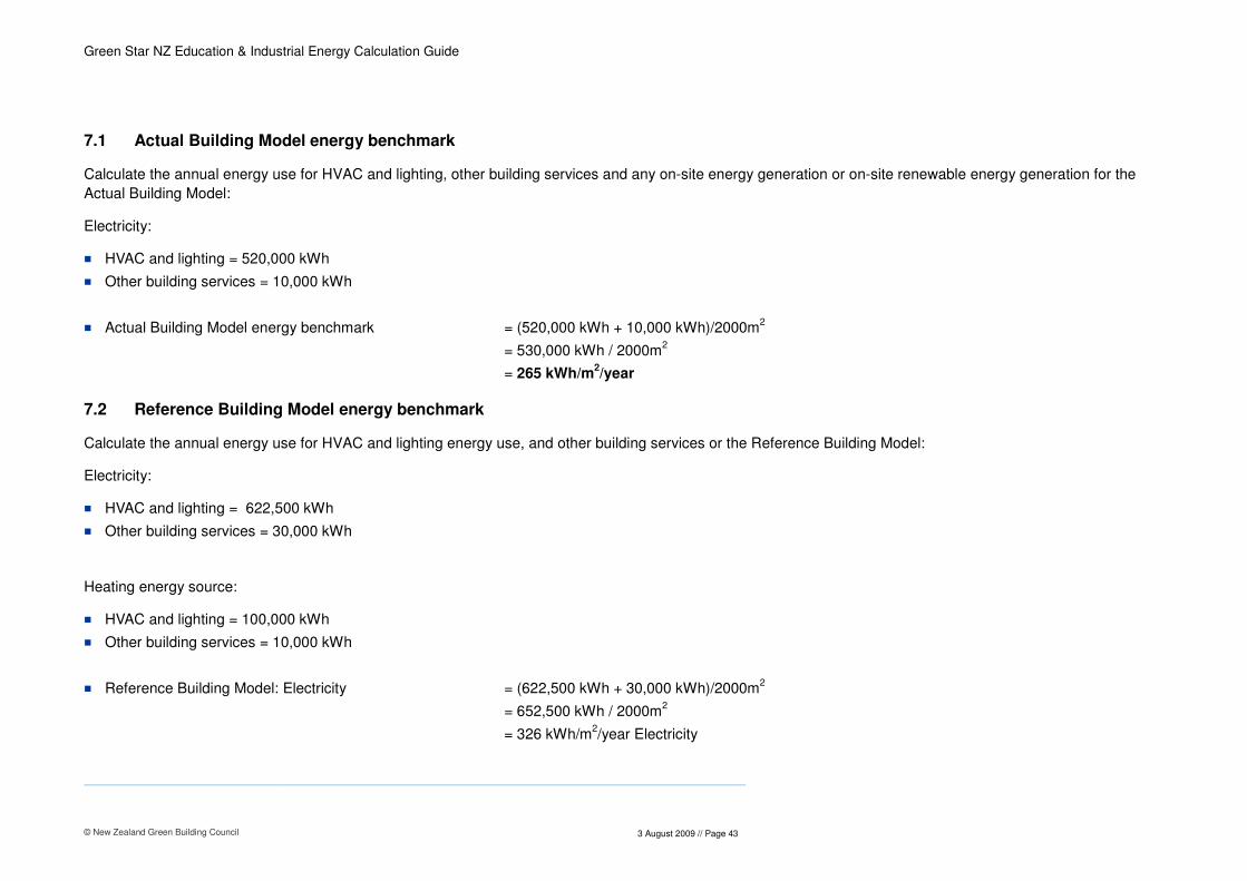
7.1 Actual Building Model energy benchmark
Calculate the annual energy use for HVAC and lighting, other building services and any on-site energy generation or on-site renewable energy generation for the
Actual Building Model:
Electricity:
� HVAC and lighting = 520,000 kWh
� Other building services = 10,000 kWh
� Actual Building Model energy benchmark = (520,000 kWh + 10,000 kWh)/2000m2
= 530,000 kWh / 2000m2
= 265 kWh/m2/year
7.2 Reference Building Model energy benchmark
Calculate the annual energy use for HVAC and lighting energy use, and other building services or the Reference Building Model:
Electricity:
� HVAC and lighting = 622,500 kWh
� Other building services = 30,000 kWh
Heating energy source:
� HVAC and lighting = 100,000 kWh
� Other building services = 10,000 kWh
� Reference Building Model: Electricity = (622,500 kWh + 30,000 kWh)/2000m2
= 652,500 kWh / 2000m2
= 326 kWh/m2/year Electricity
Green Star NZ Education & Industrial Energy Calculation Guide
© New Zealand Green Building Council
3 August 2009 // Page 44
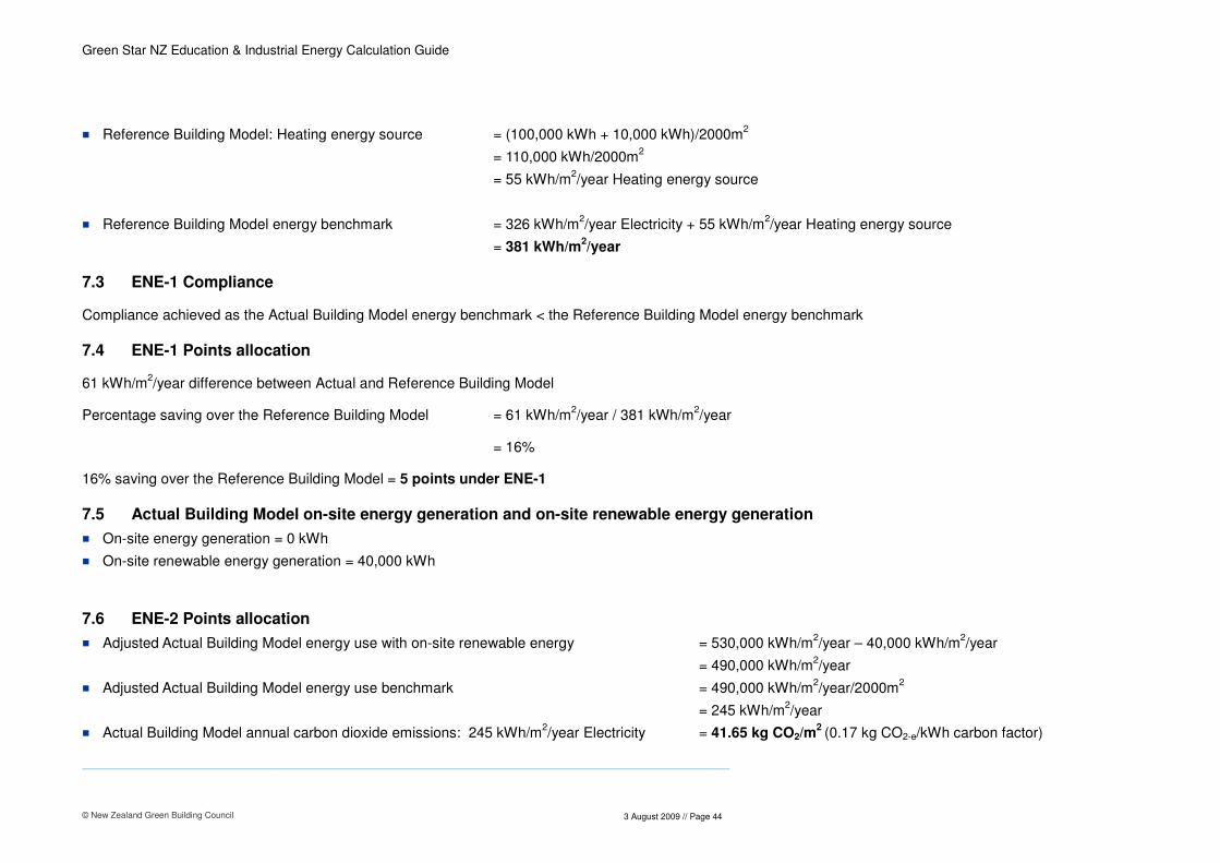
� Reference Building Model: Heating energy source = (100,000 kWh + 10,000 kWh)/2000m2
= 110,000 kWh/2000m2
= 55 kWh/m2/year Heating energy source
� Reference Building Model energy benchmark = 326 kWh/m2/year Electricity + 55 kWh/m
2/year Heating energy source
= 381 kWh/m2/year
7.3 ENE-1 Compliance
Compliance achieved as the Actual Building Model energy benchmark < the Reference Building Model energy benchmark
7.4 ENE-1 Points allocation
61 kWh/m2/year difference between Actual and Reference Building Model
Percentage saving over the Reference Building Model = 61 kWh/m2/year / 381 kWh/m
2/year
= 16%
16% saving over the Reference Building Model = 5 points under ENE-1
7.5 Actual Building Model on-site energy generation and on-site renewable energy generation
� On-site energy generation = 0 kWh
� On-site renewable energy generation = 40,000 kWh
7.6 ENE-2 Points allocation
� Adjusted Actual Building Model energy use with on-site renewable energy = 530,000 kWh/m2/year – 40,000 kWh/m
2/year
= 490,000 kWh/m2/year
� Adjusted Actual Building Model energy use benchmark = 490,000 kWh/m2/year/2000m
2
= 245 kWh/m2/year
� Actual Building Model annual carbon dioxide emissions: 245 kWh/m2/year Electricity = 41.65 kg CO2/m
2 (0.17 kg CO2-e/kWh carbon factor)

Green Star NZ Education & Industrial Energy Calculation Guide
© New Zealand Green Building Council
3 August 2009 // Page 45
� Reference Building Model annual carbon dioxide emissions: 326 kWh/m2/year Electricity = 55.42 kg CO2/m2 (0.17 kg CO2/kWh carbon factor)
55 kWh/m2/year Heating energy source = 13.75 kg CO2/m
2 (0.25 kg CO2/kWh carbon factor)
Total = 69.17 kg CO2/m2
27.52 kg CO2/m2 difference between Actual and Reference Building Model
Percentage saving over Reference Building Model = 27.52 kg CO2/m2/69.17 kg CO2/m
2
= 39.8%
40% percentage saving over the Reference Building Model = 3 points under ENE-2

Green Star NZ Education & Industrial Energy Calculation Guide
© New Zealand Green Building Council
3 August 2009 // Page 46
Appendix A
Example Project Registration Proforma
Green Star NZ Education & Industrial Energy Calculation Guide
© New Zealand Green Building Council
3 August 2009 // Page 47
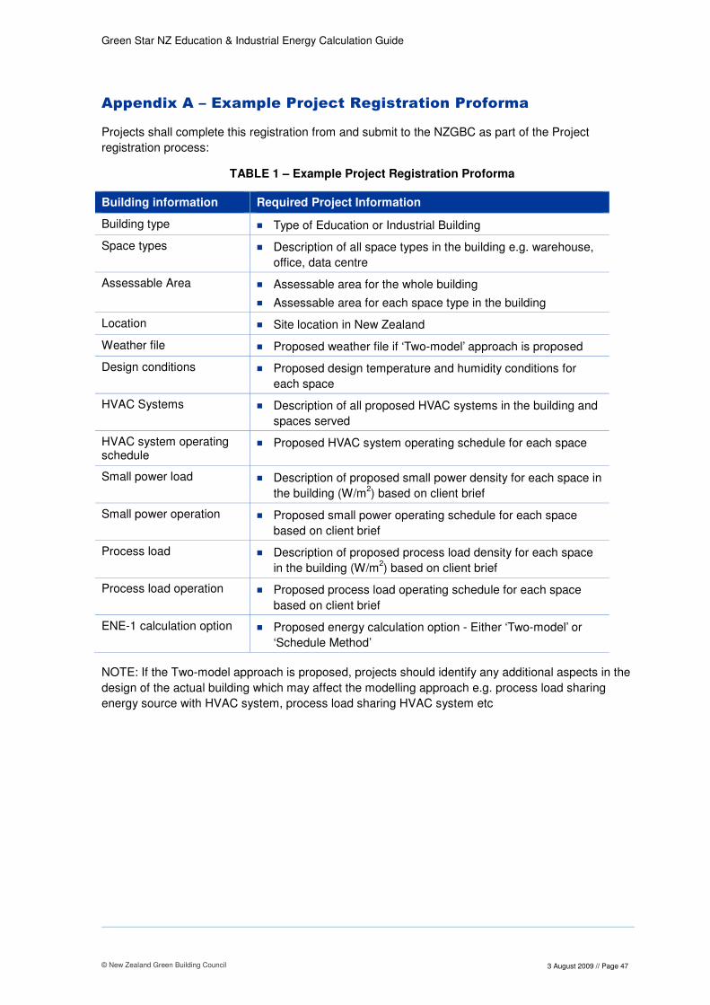
Appendix A – Example Project Registration Proforma
Projects shall complete this registration from and submit to the NZGBC as part of the Project
registration process:
TABLE 1 – Example Project Registration Proforma
Building information Required Project Information
Building type � Type of Education or Industrial Building
Space types � Description of all space types in the building e.g. warehouse,
office, data centre
Assessable Area � Assessable area for the whole building
� Assessable area for each space type in the building
Location � Site location in New Zealand
Weather file � Proposed weather file if ‘Two-model’ approach is proposed
Design conditions � Proposed design temperature and humidity conditions for
each space
HVAC Systems � Description of all proposed HVAC systems in the building and
spaces served
HVAC system operating schedule
� Proposed HVAC system operating schedule for each space
Small power load � Description of proposed small power density for each space in
the building (W/m2) based on client brief
Small power operation � Proposed small power operating schedule for each space
based on client brief
Process load � Description of proposed process load density for each space
in the building (W/m2) based on client brief
Process load operation � Proposed process load operating schedule for each space
based on client brief
ENE-1 calculation option � Proposed energy calculation option - Either ‘Two-model’ or
‘Schedule Method’
NOTE: If the Two-model approach is proposed, projects should identify any additional aspects in the
design of the actual building which may affect the modelling approach e.g. process load sharing
energy source with HVAC system, process load sharing HVAC system etc

Green Star NZ Education & Industrial Energy Calculation Guide
© New Zealand Green Building Council
3 August 2009 // Page 48
Appendix B
Reference Building Model Construction Definition

Green Star NZ Education & Industrial Energy Calculation Guide
© New Zealand Green Building Council
3 August 2009 // Page 49
Appendix B – Reference Building Model Construction Definition
Each of the Reference Building Model construction elements must be defined as described in Table 1:
Table 1 - Reference Building Model Constructions
Construction element Construction make-up from outside to inside
External walls 20mm timber cladding, Insulation, 13mm plasterboard
Roof Insulated steel roof
Ground floor and suspended floors
150mm concrete, 10mm carpet/underlay
Intermediate floors/ceilings 20mm ceiling tiles, air cavity, 100mm concrete, 10mm carpet/underlay
Partition walls 13mm plasterboard, air cavity, 13mm plasterboard
NOTE: Refer to Section 4 Table 3 for minimum R-value requirements

Green Star NZ Education & Industrial Energy Calculation Guide
© New Zealand Green Building Council
3 August 2009 // Page 50
Appendix C
Reference Building Model HVAC System Definition

Green Star NZ Education & Industrial Energy Calculation Guide
© New Zealand Green Building Council
3 August 2009 // Page 51
Appendix C – Reference Building Model HVAC System Definition
Conditioned Space Design Reference Building Model HVAC System
FIGURE 1 – Reference Building Model HVAC system determination
The Reference Building Model HVAC system must be defined as follows for each applicable system
parameter:
TABLE 1 – Reference Building Model HVAC system components
HVAC System Component
Actual Building Model attributes
Reference Building Model HVAC System Description
HVAC system type � One or multiple HVAC
system types serving
different conditioned
spaces
� One CAV multizone system serving
all conditioned spaces in the
Reference Building Model
� Hot water reheat provided for each
system zone in the Reference
Building Model to achieve design
heating space temperature
� Cooling provided via cooling coil for
each system zone in the Reference
Building Model to achieve design
cooling space temperature
System zoning � As specified � The same as the Actual Building
Model
Outdoor air rate � As specified � NZBC minimum outdoor air rate for
each conditioned space
� If space type not covered under
Conditioned space in the building is
designed to control environmental
conditions e.g. heating and/or
cooling for occupancy comfort,
heating and/or cooling to maintain
temperature for process or storage
Conditioned space in the building is
designed to be mechanically
ventilated
Conditioned space in designed to be
naturally ventilated
Constant Air Volume (CAV)
multizone system providing
ventilation, heating and cooling with
no dehumidification

Green Star NZ Education & Industrial Energy Calculation Guide
© New Zealand Green Building Council
3 August 2009 // Page 52
HVAC System Component
Actual Building Model attributes
Reference Building Model HVAC System Description
NZBC use the same outdoor air
rate as in the Actual Building Model
Supply air temperature cooling
� As specified � 10°C less than design cooling
space temperature for each
conditioned zone
� Supply air cooling temperature shall
operate as defined above during all
operating hours
Supply air temperature heating
� As specified � 10°C more than design heating
space temperature for each
conditioned zone
� Supply air heating temperature shall
operate as defined above during all
operating hours
Supply air flowrate � As specified � To achieve design conditions in
each conditioned zone using the
supply air temperatures listed
above; OR
� Additional supply air flowrate that is
required to balance extraction
Exhaust air flowrate � As specified � 80% of Reference Building Model
Supply air flowrate
Heating plant seasonal efficiency
� As specified � 80% thermal efficiency
Cooling plant EER � ≤ 525 kWr � 100% cooling load = 2.2
� 75% cooling load = 3.0
� 50% cooling load = 3.0
� 25% cooling load = 3.0
� > 525 kWr � 100% cooling load = 2.5
� 75% cooling load = 3.1
� 50% cooling load = 3.1
� 25% cooling load = 3.1
Supply and Return Fan absorbed Power
� Building assessable
area ≤ 500m2
� 12 W/m2 of building assessable
area
� Building assessable
area > 500m2
� 15 W/m2 of building assessable
area
Fan system operation � As specified � Supply and return fans shall
operate continuously during
operating hours
Chilled water and heating water pumps absorbed power
� Building assessable
area ≤ 500m2
� 3.0 W/m2 of building assessable
area
� Building assessable
area > 500m2
� 4.0 W/m2 of building assessable
area
Chilled water and heating � As specified � Constant speed

Green Star NZ Education & Industrial Energy Calculation Guide
© New Zealand Green Building Council
3 August 2009 // Page 53
HVAC System Component
Actual Building Model attributes
Reference Building Model HVAC System Description
water pumps operation � Chilled water and heating water
pumps shall operate continuously
during operating hours
Exhaust air heat recovery � Design supply air
capacity of 2400 L/s or
greater and has a
minimum outdoor air
supply of 70% or greater
of the design supply air
� Heat recovery system
� Fifty percent sensible heat recovery
effectiveness (ASHRAE)
Economiser � As specified � An economiser must be modelled
Economiser high-limit shutoff
� As specified Dependent on NZS 4243 climate zone:
� NZS:4243 Climate zone 1 = 18°C
(ASHRAE)
� NZS:4243 Climate zone 2 = 21°C
(ASHRAE)
� NZS:4243 Climate zone 3 = 21°C
(ASHRAE)
NOTE: Where reference not indicated minimum system performance values derived from NZBC
Clause H1, Guidelines for energy efficient HVAC plant2

Green Star NZ Education & Industrial Energy Calculation Guide
© New Zealand Green Building Council
3 August 2009 // Page 54
Appendix D
HVAC Modelling Requirements

Green Star NZ Education & Industrial Energy Calculation Guide
© New Zealand Green Building Council
3 August 2009 // Page 55
Appendix D – HVAC Modelling Requirements
The HVAC system must be modelled for both the Actual and Reference Building Model as follows:
TABLE 1 – HVAC modelling requirements
HVAC Modelling Parameter
Modelling Requirements
Chilled water and condenser water pumping
� Where applicable, demonstrate that chilled water pumping
and condenser water pumping is calculated using the
applicable cooling load, the static pressure of the chilled water
pumps and the flow rate
Heating hot water � Where applicable, demonstrate that heating hot water
pumping is calculated using the applicable heating load, the
static pressure of the heating hot water pumps and the flow
rate
Chiller plant � Demonstrate that the chiller plant size is accurately reflected
in the model
� Demonstrate that the actual efficiency curves of the installed
plant are used in the model
� Water cooled equipment: Demonstrate that chiller data is
specified under conditions that reflect the intended condenser
water temperature controls
� Air cooled equipment: Demonstrate that the air cooled chiller
COP profiles have been accurately modelled with regard to
loading and ambient conditions
Heating plant � Demonstrate that the heating plant type, size, thermal
efficiency and distribution efficiency are accurately reflected in
the model.
Supply air and exhaust fans
� Demonstrate that fan performance curves are accurately
represented in the model
� Demonstrate that index run pressure drops are accurately
represented to include the total static inclusive of filters, coils
and diffusers
� Ensure that the calculated fan energy uses the total fan
pressure (static + dynamic)
� Ensure that the fan efficiency is the product of the motor and
fan efficiency
Heat rejection fans � If applicable, demonstrate that allowance for energy
consumption from heat rejection fans has been made, based
upon the annual cooling load of the building and the
supplementary cooling load for tenancy air conditioning
Cooling tower and condenser water pumping
� If applicable, demonstrate that allowance for energy
consumption from cooling tower and condenser water
pumping has been made, based upon the annual cooling load
of the building
Outdoor air � Demonstrate that outdoor air flows have been modelled as
documented in the mechanical design drawings and
specifications, and in compliance with the appropriate
standards

Green Star NZ Education & Industrial Energy Calculation Guide
© New Zealand Green Building Council
3 August 2009 // Page 56
HVAC Modelling Parameter
Modelling Requirements
� Demonstrate that the minimum outdoor air rate claimed in
IEQ-2 Credit is achieved in the model
Economiser � Demonstrate that any economy cycles have been modelled to
reflect system specification noting any enthalpy/temperature
cut-off and control point
Primary duct temperature control
� Constant Volume Systems: Demonstrate that modelling has
allowed supply air temperatures to vary to meet loads in the
space
� Variable Volume Systems: Demonstrate that modelling has
allowed supply air volumes to vary to meet loads in the space
� Demonstrate that set-points have been rescheduled as
specified. Note that simplifications may be made to consider
average zone temperature in lieu of high/low select
Airflow Control � Demonstrate that control logic describing the operation of the
dampers to control outside and recirculated airflow is inherent
in the model and accurately reflects the airflow characteristics
of the system
Minimum turndown � Demonstrate, where relevant, that the minimum turndown
airflow of each air supply is accurately reflected in the model
while still achieving the minimum outdoor air claimed in IEQ-2
Credit
Chiller/compressor staging � Demonstrate that for systems that employ multiple chillers
with a chiller staging strategy, the correct controls are
modelled to reflect the actual relationship between the chillers.
� For refrigeration systems that use a cascading series of
compressors, demonstrate that the COP incorporated is
representative of the entire series.
Temperature and humidity control bands
� Demonstrate that the thermal model accurately reflects the
temperature and humidity control bands of the system

Green Star NZ Education & Industrial Energy Calculation Guide
© New Zealand Green Building Council
3 August 2009 // Page 57
Appendix E
Lift Energy Use Calculation

Green Star NZ Education & Industrial Energy Calculation Guide
© New Zealand Green Building Council
3 August 2009 // Page 58
Appendix E – Lift Energy Use Calculation
Please Note that the description below demonstrates the method of calculation only. The actual
figures for standard number of trips per year and time for each trip for the facility modelled should be
provided and justified. Also the number of trips and typical time for each trip would vary based on if the
lifts are intended for passenger use or to ferry goods. If both types of lifts are incorporated then each
would need to be calculated separately.
To calculate lift energy use:
� Determine the lift power ratings R in kW from supplier specifications;
� Determine the Standby power from car lights and lift control system in kW from supplier
specifications; and then
� Calculate the annual Energy usage using the following formula
E = (R x S x T (100% + P)/3600 + (St x Hrs x 260)) x No. Lifts
Where:
E = Annual Energy usage (kWh/year)
R = Power Rating of the motor (kW)
S = Number of Starts per year (S=300,000 for the purposes of the Green Star – Education or Industrial
2009 lift energy calculations)
T = Typical Trip time (seconds) (T=5s for the purposes of the Green Star – Education or Industrial
2009 lift energy calculations)
P = Penalty factor
- Where lifts with speeds over 2.5 m/s have regenerative brakes, P=0%
- Where lifts with speeds over 2.5 m/s do not have regenerative brakes, P=15%
St = Standby power – car lights and lift control systems (kW)
Hrs = number of hours per day lifts are operating
- Where lift has a power off feature, hrs = 18
- Where lift does not have a power off features, hrs = 24
No. Lifts = Number of lifts of this type in the project under assessment.
Note that:
� The figure of 3600 converts the first half of the equation, which is in kWs, into kWh.
� The hours x 260 takes the standby power and multiplies it by operational hours and days in a year
to get annual energy consumption.
� If a lift only services three floors, is to solely be used as a disabled lift and is labelled as such, the
energy consumption of this lift can be discounted by 90%.

Green Star NZ Education & Industrial Energy Calculation Guide
© New Zealand Green Building Council
3 August 2009 // Page 59
References
1 NZS:4243 Energy Efficiency – Large Buildings, Part 1: Building Thermal Envelope
2 http://www.dbh.govt.nz/energy-efficient-hvac-plant-guidelines