Embed Size (px)
Citation preview

This article was downloaded by: [Tarek Tutunji]On: 07 October 2011, At: 01:55Publisher: Taylor & FrancisInforma Ltd Registered in England and Wales Registered Number: 1072954 Registeredoffice: Mortimer House, 37-41 Mortimer Street, London W1T 3JH, UK
European Journal of EngineeringEducationPublication details, including instructions for authors andsubscription information:http://www.tandfonline.com/loi/ceee20
Mechatronic system design course forundergraduate programmesA. Saleem a , T. Tutunji a & L. Al-Sharif aa Department of Mechatronics, Philadelphia, University, Amman,Jordan;b Department of Mechatronic Engineering, University of Jordan,Amman, Jordan
Available online: 22 Jul 2011
To cite this article: A. Saleem, T. Tutunji & L. Al-Sharif (2011): Mechatronic system design coursefor undergraduate programmes, European Journal of Engineering Education, 36:4, 341-356
To link to this article: http://dx.doi.org/10.1080/03043797.2011.593094
PLEASE SCROLL DOWN FOR ARTICLE
Full terms and conditions of use: http://www.tandfonline.com/page/terms-and-conditions
This article may be used for research, teaching, and private study purposes. Anysubstantial or systematic reproduction, redistribution, reselling, loan, sub-licensing,systematic supply, or distribution in any form to anyone is expressly forbidden.
The publisher does not give any warranty express or implied or make any representationthat the contents will be complete or accurate or up to date. The accuracy of anyinstructions, formulae, and drug doses should be independently verified with primarysources. The publisher shall not be liable for any loss, actions, claims, proceedings,demand, or costs or damages whatsoever or howsoever caused arising directly orindirectly in connection with or arising out of the use of this material.
European Journal of Engineering EducationVol. 36, No. 4, August 2011, 341–356
Mechatronic system design course for undergraduateprogrammes
A. Saleema*, T. Tutunjia and L. Al-Sharifb
aDepartment of Mechatronics, Philadelphia University, Amman, Jordan; bDepartment of MechatronicEngineering, University of Jordan, Amman, Jordan
(Received 6 September 2010; final version received 14 May 2011)
Technology advancement and human needs have led to integration among many engineering disciplines.Mechatronics engineering is an integrated discipline that focuses on the design and analysis of completeengineering systems. These systems include mechanical, electrical, computer and control subsystems. Inthis paper, the importance of teaching mechatronic system design to undergraduate engineering students isemphasised. The paper offers the collaborative experience in preparing and delivering the course materialfor two universities in Jordan. A detailed description of such a course is provided and a case study ispresented. The case study used is a final year project, where students applied a six-stage design procedurethat is described in the paper.
Keywords: mechatronics education; design procedure; student projects
1. Introduction
Mechatronic engineering has gained much interest in recent years due to the advancement ofintegrated engineering systems (Ebert-Uphoff et al. 2000). Design, analysis and integration ofmechanics with electronics through intelligent algorithms for control applications are fundamentalelements in mechatronics education.
An essential engineering skill that must be taught to undergraduate students is design. Thisskill is usually built up and taught to students through a combination of problem-solving skills,dedicated courses and projects. Nevertheless, constructing (and teaching) engineering designrequires much more preparation and skill as compared to the traditional courses. The reasonsfor the difficulty in teaching such courses are due to the fact that design involves open-endedproblems with several possible solutions. So, there is no specific single correct answer. This isusually a challenge to the students and should be provided to them in a well-constructed coursethrough practical examples.
There are many engineering schools that offer engineering design courses (Lee 2009). Admit-tedly, there are general steps and abstract guidelines that form a common base among allengineering schools. Nevertheless, teaching methods differ among different universities and
*Corresponding author. Email: [email protected]
ISSN 0304-3797 print/ISSN 1469-5898 online© 2011 SEFIDOI: 10.1080/03043797.2011.593094http://www.informaworld.com
Dow
nloa
ded
by [
Tar
ek T
utun
ji] a
t 01:
55 0
7 O
ctob
er 2
011

342 A. Saleem et al.
among different disciplines. In this paper, an argument will be made that today’s engineeringneed is to prepare the students for an integrated design system approach.
The mechatronic system design course is best suited for mechanical, electrical and/or controlengineering disciplines. It is constructed for senior students who have already finished the fol-lowing courses: body mechanics; electronics; motors; sensors; programming; control. In effect,it is a good example of a taught capstone course.
In Craig (2001), researchers described an undergraduate programme that offers as a core twoclasses: Mechatronics and Mechatronic System Design. The authors argue that an essential char-acteristic of a mechatronics engineer is a balance between modeling/analysis skills and hardwareimplementation skills. A block diagram of a dynamic system investigation was provided anddetails for the two courses were given. In Singhose et al. (2009), the authors emphasised theimportance of hands-on, project-based, design experience. The described course is an introductionto mechatronics course, where they discussed the general lectures supported by laboratory works.
Other researchers discussed their experience in teaching design courses. Jarrah (2005) proposeda mechatronics design course intended for graduate students and worked on design laboratory-like experiments that led to a product. Moreover, details for such a course for undergraduateswere provided in Tutunji et al. (2009), where the authors presented, evaluated and discussedthe guidelines for a successful mechatronics project class. Denayer et al. (2003) presented anundergraduate design course by problem-based education.
Capstone courses find applications in many areas of engineering, such as engineering appli-cations in biology and medicine (Goldberg 2009) and electrical and computer engineering (Saad2007) as well as electromagnetic. Ideally, the capstone project should relate to real life as much aspossible. Some studied the effect of prior industry experience on the success of capstone projects(Gruenther et al. 2009).
In this paper, the experience gained in developing the mechatronic system design course atPhiladelphia University (Jordan) and the University of Jordan will be discussed. This will includethe course objectives, teaching methodologies, material and outcomes.
The importance of this paper derives from the fact that the Mechatronics System Design course isa relatively new course and is not as well established as other more traditional courses (e.g. controlsystems, electrical machines). For this reason, the contents of this course and the method of deliv-ery of such a course are not widely documented. This paper introduces a detailed ‘road-map’for therecommended course content and the method of delivery. It also contains topics that are not tradi-tionally taught in engineering undergraduate programmes, such as detailed components selection.
The rest of the paper is organised as follows. Section 2 presents the course outcomes and topics.Section 3 provides an overview on actuators and sensors and their selection, while controllers,algorithms and interfacing are presented in section 4. Section 5 explains the system design pro-cedure that is being delivered in the course. A detailed students’ project that is used as a caseexample is given in section 6. Finally, section 7 concludes this paper.
2. Course outcomes and topics
The Mechatronics System Design course is given to senior students as part of the mechatronicscurriculum at Philadelphia University and University of Jordan. The course objective is to preparethe students to work with practical and fully integrated systems. At the end of the course, studentsare expected to have the following outcomes:
• Evaluate and select suitable actuators, sensors, controllers and algorithms.• Integrate and interface various components and subsystems.• Follow a well-defined design procedure.
Dow
nloa
ded
by [
Tar
ek T
utun
ji] a
t 01:
55 0
7 O
ctob
er 2
011

European Journal of Engineering Education 343
Mechatronic systems contain integrated subsystems as shown in Figure 1. These subsystemsshould be known to the students, who are expected to have taken courses in mechanics, sensors,control theory, microcontroller, electronics and electrical motors. The main idea of the course isto review and interface the described subsystems in order to design fully integrated systems thatmeet specified requirements. The course covers the following main topics:
• Introduction to mechatronic systems: overview of mechatronic systems; applications inindustry, space, medicine, home appliances and automotive.
• General engineering principles: description of a number of general engineering principles;basics of testing and troubleshooting.
• Electrical actuators: revision and selection among different motor types.• Sensors and transducers: revision and selection among different sensor types.• Control systems: overview and selection of physical controllers and control algorithms.• Interconnection and interfacing: review of drive circuits, conditioning circuits and data
acquisition systems.• Mechatronic system design procedure: detailed study of the mechatronic system design stages.• Case studies: Selected case studies to reinforce the principles and the design procedure.
The course is normally delivered through three stages. In the first stage, students are exposedto theoretical material, which covers the previous mentioned topics. Parallel to the theoreticallectures, students carry out laboratory experiments to reinforce the concepts delivered in theclass, using standard experiments kits such as elevators, production lines and robot manipulators.All these experiments are carefully designed in order to suit the practical requirements of the
Mechanical System (e.g. Robot
Production System Automobile)
Sensor(e.g. Position
SpeedTemperaturePressure)
Actuator(e.g. Electric PneumaticHydraulic)
Controller(e.g. Computer, PLC, embedded
system)
SignalConditioning(e.g. Amplifiers
ADCFilter)
Power Interface (e.g. H-Bridge, Pump, Power OP AMPS)
Figure 1. Mechatronic system block diagram. PLC = programmable logic controller.
Dow
nloa
ded
by [
Tar
ek T
utun
ji] a
t 01:
55 0
7 O
ctob
er 2
011

344 A. Saleem et al.
Figure 2. Lecture time allocation.
course. Finally, students are required to conduct group projects, where they must apply designprinciples and components selection.
Figure 2 shows the lecture time allocation for the listed topics. This is a three credit hour course,which has 40 hours of lecture time. The first two topics, introduction and general principles, aremainly used to prepare the student for the course and will not be covered in this paper becausethey are general terms and can be easily found in the literature. The rest of the topics will bediscussed in the following sections.
3. Actuators and sensors
Actuators are the driving force in mechatronic systems and therefore are covered first. Studentsare reminded of the large range of actuators that are used in practice, whether rotary or linear andwhether electrical, electromagnetic, pneumatic or hydraulic. This course, however, only coversthe rotary electric actuators in detail, leaving the linear electric actuators to exercises and casestudies. Pneumatic and hydraulic actuators are taught in a separate dedicated course.
The students are introduced to various factors that influence the selection of rotary electricactuator that include:
• positioning accuracy;• power and torque requirements;• continuous and intermittent duty cycles;• speed range.
Three examples are given to allow the student to gain experience in selecting motors for threemechatronic systems: a conveyor belt using a stepper motor; an elevator using an inductionmotor; an electric vehicle using a permanent magnet DC motor. The examples aim to link thebasic concepts in mechanics with the electrical and mechanical performance of the motor underconsideration and the overall system requirements. It also allows the student to gain good experi-ence in dealing with mechanics in terms of balance masses and rotational inertias. These examplesprepare the student for dealing with practical systems and make the exercises more enjoyable.
Sensors play an important role in mechatronic systems. They are usually utilised in mechatronicsystems to measure: (1) system outputs for feedback control; (2) system inputs for feed-forward
Dow
nloa
ded
by [
Tar
ek T
utun
ji] a
t 01:
55 0
7 O
ctob
er 2
011
European Journal of Engineering Education 345
control; (3) output signals for system monitoring, diagnosis, evaluation, parameter adjustment andsupervisory control. Students should be given a brief review of the usage of sensors to measurephysical variables, such as temperature, pressure, force, speed and flow. Moreover, students shouldunderstand the differences among sensors within the same category in order to appreciate relativestrengths and weaknesses for each sensor type.
Students should also comprehend sensor characteristics such as sensor range, sensitivity, accu-racy, precision, linearity, resolution and frequency response.After reviewing these topics, studentsshould have gained enough understanding in the selection of the appropriate sensors to be used.
4. Control systems and interfacing
The design of mechatronic systems involves the choice of the controller. This is arguably the mostcritical decision in the design process. A vast variety of controllers are available on the market.The following is a list of the four main controller groups as explained to the student:
• A programmable logic controller (PLC) is a user-friendly, microprocessor-based, specialisedcomputer that is used for process control. It contains input/output (I/O) modules for appropriatesensors/actuator interfaces. It is mainly used in automated manufacturing lines. The PLC isusually used for simple logic operations. It is considered reliable and easy to program (usingladder diagrams, instructions, or function blocks).
• The microcontroller is a computer-on-chip. It is an integrated circuit that contains micropro-cessor, memory, I/O parts and sometimes A/D converters. It can be programmed using severallanguages (such as Assembly or C/C++). It can be used in manufacturing lines, but requiresadditional hardware. Microcontrollers are mainly used in engineering products such as washingmachines and air-conditioners.
• Digital signal processors (DSP) are specialised microprocessors with advanced architectures(such as multiple buses, parallel processing, hardware multipliers and fast sampling rate) that aredesigned to reduce the number of instructions and operations necessary for efficient processing.DSP chips enable developers to implement complex algorithms and perform computationallyefficient and fast algorithms. DSP are preferred over microcontrollers when the need for com-plex and iterative control algorithms is required. Applications vary from hard disk drives tomissile control.
• Personal computers are used when extensive signal processing and in-depth analysis is required.Advantages include superior graphical and software flexibility. However, the cost is high and,therefore, they are not suitable for a large number of products.
Students are introduced to different systems and are asked to consider what the most suitablecontroller for such a system is. In many cases, there is no one single correct answer. The studentis encouraged to consider all the factors that might influence the decision in terms of space,processing power, environment, cost of final product, programming language, safety criticality ofthe application, required time to market, reliability and number of products to be produced.
Another critical decision that the student must make is the type of control algorithm to use.It is important to highlight to the student that the decisions as to the controller used and thecontroller algorithm are interdependent. There are many controller algorithms that can be usedfor mechatronic systems. The following is a list of three that are explained to the student:
• On-Off control: This is the simplest method of control. The control action has three possibleoutputs: on; off; no change. This method is usually used for slow-acting operations (such as arefrigeration unit). The advantage is its ease of design and low cost. However, it cannot varythe controlled variable with precision. The student is introduced to simple examples, such as a
Dow
nloa
ded
by [
Tar
ek T
utun
ji] a
t 01:
55 0
7 O
ctob
er 2
011

346 A. Saleem et al.
domestic heating system, the exact temperature of which is not critical. This is an ideal exampleof a simple on/off controller application.
• Proportional-integral-derivative (PID) control: This is the most commonly used controlleralgorithm. It is applied in automated manufacturing and mechatronic products. In its sim-plest mode, only the proportional part is used. The error between the desired and measuredvalues of the controlled variable is calculated, multiplied by a gain and applied to the systemunder control. An integral mode is usually added to minimise the steady state error while aderivative mode is added to minimise the transient overshoot (Ang et al. 2005).
• Intelligent control: When the system to be controlled does not have a well-defined mathematicalmodel because of high non-linearities or missing information, fuzzy or neural controllers areapplied. Fuzzy controllers are used when general fuzzy control rules can be gathered from anexpert. Neural network controllers are used when experimental I/O data are available from thesystem.
An important skill that students should master within the area of mechatronics system design isinterfacing the controller to the physical system. Students usually take the function of interfacingfor granted without understanding its criticality and importance.
Within this course, students learn the importance of switching (whether electromechanical orelectronic) concepts. These include:
• voltage and current rating limitations of electronic devices (e.g. microcontrollers);• the use of contactors and relays in switching loads;• the use of the transistor as a switch or a current amplifier;• the use of drivers and H-bridges;• the use of opto-isolators to separate circuits in order to prevent noise and damage.
5. Design procedure
Knowledge of sensors, actuators, controllers and interfacing prepares students for the design ofmechatronic systems. The following is a summary of the mechatronic system design procedureand stages that are covered in this course.
5.1. User and system requirements analysis
Typically, the mechatronic system design lifecycle starts with the user requirements analysis stagein order to acquire the system’s specifications and requirements. Critical benefits such as enhancedquality of work, reduction in support and training costs and improved user satisfaction can beachieved.
Next, the system requirements can be determined. System requirements analysis can be achallenging phase, because all of the major customers and their interests are brought into theprocess of determining requirements. The quality of the final product is highly dependent on theeffectiveness of the requirements identification process. These requirements form the basis for allfuture work on the project, from design and development to testing and commissioning. It is ofthe highest importance that the system designer creates a complete and accurate representationof all requirements that the system must accommodate.
5.2. Conceptual design
A conceptual design embodies the structure of the system, as perceived by the user. This structureis a formulation of the conceptual ideas to meet the requirement specifications, which are the
Dow
nloa
ded
by [
Tar
ek T
utun
ji] a
t 01:
55 0
7 O
ctob
er 2
011

European Journal of Engineering Education 347
results from the previous phase. The input and goals of the conceptual design process form therequirement specifications to be met. It is always more expensive to improve a bad conceptualdesign than a bad detailed design; therefore, this process is crucial and essential.
This process generates solutions without detailed design parameters and acts as a blueprintfor the subsequent design and implementation stages. New requirements may arise within theprocess, which should be considered. After generating concepts and meeting all the requirements,the optimal concept and solution can then be selected, if accepted by the customer. By the end ofthis stage, a system block diagram and operation flowchart should be available.
5.3. Mechanical, software, electronics, and interface design
The mechanical design is crucial since it forms the skeleton of mechatronic systems. The designcan be supported by computer-aided design (CAD) tools, which are widely available in industry.During the mechanical design process, the control system should be evaluated and designedsynergistically with the mechanical design.
If the optimal mechanical design is achieved, the designer should move to select the actuatorsand sensors that can meet the demand specifications. This should then be followed by selectingthe drive and conditioning circuits in order to interface the system components.
A mechatronic system is an integrated engineering design, which can be complex to design andoptimise since it covers several engineering domains, as shown in Figure 1. Optimising each partseparately might not result in the best design. Therefore, it is essential to establish the optimaltrade-offs between the mechanical and electronic subsystems. This is done through synergisticdesign, where the system design is divided into three parallel tracks (see Figure 3):
• The design of the mechanical frame/machine.• The design of the electronic system.• The design of the software/controller.
During the design, the interface among these tracks should be evaluated continuously in orderto optimise the system performance. This usually results in design modifications of the individualtracks.
5.4. System modelling and simulation
Mechanical, electrical and electronic components should be included in a mixed system model ofthe plant. Initially, such a model should be fairly simple. A linear time-invariant model with oneinput and one output is often adequate at the initial modelling stage, even for relatively complexmechatronic systems.
System Design
Software/ControlDesign
ElectronicsDesign
MechanicalDesign
Design Integration
Interface Interface
Figure 3. Synergistic design.
Dow
nloa
ded
by [
Tar
ek T
utun
ji] a
t 01:
55 0
7 O
ctob
er 2
011

348 A. Saleem et al.
The model parameters should be determined based on the designed mechanical componentsand the selected actuators and sensors. The designer has the freedom to modify these values,increase the number of inputs/outputs used and include non-linearities in the subsequent designiterations.
Once a plant model is available, simulation is used to decide on the design specificationsof the mechatronic system based on the specification of requirements. Specifications can bemade in a variety of forms, such as rise time, bandwidth, gain margin and pole/zero loca-tions. If the simulation results do not satisfy the design specifications, the designer should revisitstage 3.
The simulation can be divided into three parts: mechanical; electronic; system. Mechan-ical simulation is used to test the kinematics and dynamics variables, electronic simulationis used to test circuit functionality and compatibility and the system simulation is normallyused to test the system’s response for different inputs (open and closed loop cases). For themechanical simulation, students are advised to use software tools such as ProEngineer and Solid-Works. For the electronic and system simulation, they are advised to use Protus and Matlabrespectively.
5.5. Prototyping and testing
Once the model is verified by simulation, the physical system prototype should be assembled andtested in the laboratory. If the prototype does not satisfy the design specifications, at this stagethe designer should check to see whether some modifications to the plant could yield the requiredresults. If the plant modifications could realise the desired performance, the design process shouldstop here. Otherwise the designer should reconsider the control system design.
6. Case study
A Robotic Parking Garage project is a final year project conducted in Philadelphia University.The students followed the design procedure described in this paper and the output was a workingprototype. Robotic parking is a method of automatically parking and retrieving cars, using acomputerised system. After brainstorming, the following requirements were set:
• An area to determine all the parameters of the desired car, such as length, width, height, weightand security parameters, provided an indicator to interface between driver and the system. Allcar dimensions have been scaled down with a ratio 20:1, and hence the dimensions were asfollows:– maximum height = 100 mm– maximum width = 110 mm– maximum length = 220 mm– maximum weight = 1 kg
• Appropriate measures must be provided to deny access to cars exceeding the capacity of thesystem.
• Two gates, if all vehicle parameters are appropriate and if a free space exists, one of the gateswill be opened to enter the desired vehicle to the system; otherwise the other gate will beopened.
• The robot shall be capable of handling a maximum weight of vehicle, at an appropriatespeed in order to have a maximum car parking time of two minutes and retrieving time of10 minutes.
Dow
nloa
ded
by [
Tar
ek T
utun
ji] a
t 01:
55 0
7 O
ctob
er 2
011

European Journal of Engineering Education 349
Figure 4. System block diagram.
Figure 5. Operational flow chart.
Dow
nloa
ded
by [
Tar
ek T
utun
ji] a
t 01:
55 0
7 O
ctob
er 2
011

350 A. Saleem et al.
Figure 6. CAD model of the measuring area.
Figure 7. Robot arm CAD model.
Dow
nloa
ded
by [
Tar
ek T
utun
ji] a
t 01:
55 0
7 O
ctob
er 2
011

European Journal of Engineering Education 351
Figure 8. Building structure computer-aided drawing model.
Many concepts for the system design emerged. After deeply analysing and consulting thesystem requirements, best concept was selected and adopted. The system consisted of four mainsubsystems:
(1) Measuring area: where all car dimensions and parameters are measured via sensors and fedback to the main computer.
(2) Gates: which route cars either to the park or to the exit. The gates are activated by motors.
Table 1. Selected actuators and sensors
Subsystem Actuators Sensors
Measuring area NA • Three infrared sensors for height andlength measurements.
• Six springs and limit switch for theweight measurement.
Gates Two DC motors; one for each gate Four limit switches; two for each gate.Logging system NA Fingerprint readerRobot arm • Three DC motors for the joints.
• One DC for the end effecter• Linear encoder for the up–down
motion.• Rotary encoder for the rotational
motion.• Two limit switches for the in–out
motion• Two limit switches for the end
effecter motion
Dow
nloa
ded
by [
Tar
ek T
utun
ji] a
t 01:
55 0
7 O
ctob
er 2
011
352 A. Saleem et al.
Table 2. Robot Denenvit-Hartenberg parameters
Joint # αi−1 ai−1 di θi
1 0 0 d1 02 0 L1 0 θ23 90◦ 0 L2 + d2 0
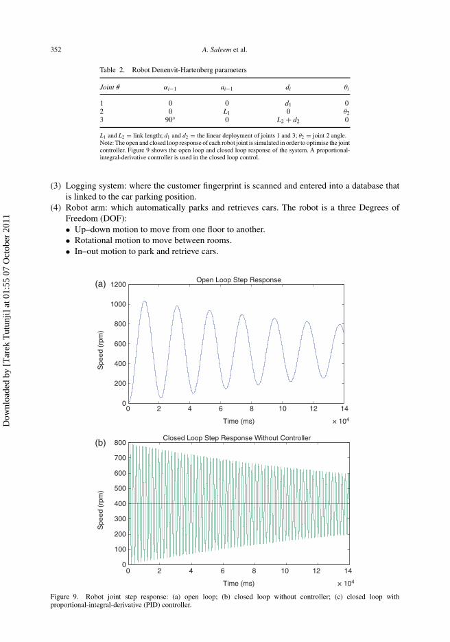
L1 and L2 = link length; d1 and d2 = the linear deployment of joints 1 and 3; θ2 = joint 2 angle.Note: The open and closed loop response of each robot joint is simulated in order to optimise the jointcontroller. Figure 9 shows the open loop and closed loop response of the system. A proportional-integral-derivative controller is used in the closed loop control.
(3) Logging system: where the customer fingerprint is scanned and entered into a database thatis linked to the car parking position.
(4) Robot arm: which automatically parks and retrieves cars. The robot is a three Degrees ofFreedom (DOF):• Up–down motion to move from one floor to another.• Rotational motion to move between rooms.• In–out motion to park and retrieve cars.
0
200
400
600
800
1000
1200(a)
(b)
Spe
ed (
rpm
)
0
100
200
300
400
500
600
700
800
Spe
ed (
rpm
)
Open Loop Step Response
Closed Loop Step Response Without Controller
0 2 4 6 8 10 12 14
× 104Time (ms)
0 2 4 6 8 10 12 14
× 104Time (ms)
Figure 9. Robot joint step response: (a) open loop; (b) closed loop without controller; (c) closed loop withproportional-integral-derivative (PID) controller.
Dow
nloa
ded
by [
Tar
ek T
utun
ji] a
t 01:
55 0
7 O
ctob
er 2
011

European Journal of Engineering Education 353
(c)
0 2 4 6 8 10 12 14
× 104
0
50
100
150
200
250
300
350
400
450
Spe
ed (
rpm
)
Time (ms)
Step Response With PID Control
Figure 9. Continued.
Figures 4 and 5 show the block diagram and the flowchart explaining the main subsystems andtheir connection as well as the operation sequence of the system.
After deciding on the concept, students started with the mechanical design. A CAD model ofthe measuring area, robot arm and building structure were developed as shown in Figures 6, 7and 8. Next, students worked on component selections as shown in Table 1.
Figure 10. The implemented measuring area.
Dow
nloa
ded
by [
Tar
ek T
utun
ji] a
t 01:
55 0
7 O
ctob
er 2
011

354 A. Saleem et al.
Figure 11. The implemented robot arm.
Figure 12. The overall system prototype.
Dow
nloa
ded
by [
Tar
ek T
utun
ji] a
t 01:
55 0
7 O
ctob
er 2
011

European Journal of Engineering Education 355
Once all components were selected, students started looking at different interface circuits to beused. Those included power conversion, power drive and conditioning circuits. All circuits weredesigned, tested in simulation and implemented in the laboratory.
The system has two main parts to control the measuring area and two barriers and the robot. Acomputer was selected as a controller and two control algorithms were used: (1) on/off controlfor the gates and the holding platform; (2) PID control for the robot joints. All control algorithmswere verified using simulation tools.
In order to verify the design, system modelling and simulation are performed. First, Denenvit-Hartenberg parameters for the robot arm shown in Figure 7 are created and shown in Table 2.Forward and inverse kinematic simulation is then performed using Matlab.
As shown in Figure 9a, the robot joint speed oscillates around the set point (400 rpm) with avery long settling time. After feeding the speed back to the PID controller, the system responseimproved and quickly settled around the set point. Figure 9c shows the system response aftertuning the PID controller where the overshoot, rise time and settling time are reduced.
After verifying the system design through computer simulation, all components for the systemwere acquired in order to assemble/integrate the system. Figures 10, 11 and 12 show the imple-mented prototype. The prototype was then tested for further improvements to satisfy system andcustomer requirements.
7. Conclusions
The Mechatronics System Design course is one of the most important courses that is studied bymechatronics undergraduate students. It acts as a capstone course that integrates all the knowledgeand skills that the student has acquired in earlier years and, in many cases, prepares the studentfor the final-year graduation project.
This paper has presented an overview of the course contents and the appropriate delivery methodby the use of case studies and examples. It is argued that such a design course requires a highlevel of integration between the various topics and skills and thus requires a special approach inits content and delivery. It should also encourage the student to use practical examples in orderto address and solve real-life problems.
Prior to discussing the design process itself, selection criteria and methodology for the maincomponents were reviewed. The correct selection procedures of the transducers and actuatorsfor a mechatronics system were reviewed. This is followed by a topic that is rarely discussedin conventional literature: the selection of the physical implementation of the controller and theselection of the suitable control algorithm. The use of an on/off simple controller for certainapplications is emphasised to the students to encourage them to think of simple solutions first,where appropriate, before embarking on the more complicated options.
A systemic approach to the design of a mechatronic system was formulated. The steps to befollowed in such a design process were detailed.A robotic garage case study was discussed in somedetail in order to illustrate how the students applied the design methodology in their final-yearproject. It is argued that such a design process can be applied to any mechatronic system.
Acknowledgements
The authors would like to thank Philadelphia University for hosting and financing the student project. The authors wouldalso like to thank the students who worked on the robotic parking garage projects; Mohammad I. Al-Qadi and MohammadS. Al-Zukari.
Dow
nloa
ded
by [
Tar
ek T
utun
ji] a
t 01:
55 0
7 O
ctob
er 2
011
356 A. Saleem et al.
References
Ang, K.H., Chong, G. and Li,Y., 2005. PID control system analysis, design, and technology. IEEE Transactions on ControlSystems Technology, 13 (4), 559–576.
Craig, K., 2001. Is anything really new in mechatronics education? IEEE Robotics & Automation Magazine, 8 (2) 12–19.Denayer, I., et al., 2003. Teaching a structured approach to the design process for undergraduate engineering students by
problem-based education. European Journal of Engineering Education, 28 (2), 203–214.Ebert-Uphoff, I., et al., 2000. Preparing for the next century: the state of mechatronics education. IEEE/ASME Transaction
on Mechatronics, 5 (2), 226–227.Goldberg, J.R., 2009. Design verification in capstone design courses. IEEE Engineering in Biology and Medicine
Magazine, January/February, 28 (1), 87–88.Gruenther, K., et al., 2009. The influence of prior industry experience and multidisciplinary teamwork on student design
learning in a capstone design course. Design Studies, 30, 721–736.Jarrah, M.A., 2005. Teaching mechatronics design course for engineers. IEEE Workshop on Advanced Robotics and its
Social Impacts, 12–15 June 2010, Nagoya, Japan.Lee, N., 2009. Project methods as the vehicle for learning in undergraduate design education: a typology. Design Studies,
30 (5), 541–560.Saad, A., 2007. Senior capstone design experiences for ABET accredited undergraduate electrical and computer
engineering education. Proceedings of the IEEE Southeastcon, 22–25 March 2007, Virginia, USA, Vols. 1–2,294–299.
Singhose, W., Vaughan, J. and Mayor, R., 2009. Use of design competitions in mechatronics education. Proceedings ofIEEE international conference on mechatronics, 14–17 April 2009, Malaga, Spain.
Tutunji, T., Saleem, A. and Rabbo, S.A., 2009. An undergraduate mechatronics project class at Philadelphia University,Jordan: methodology and experience. IEEE Transactions on Education, 52 (3), 365–374.
About the authors
Ashraf Saleem is currently serving as an Assistant Professor at the Mechatronics Department at Philadelphia University(Jordan). He obtained his BSc in computer engineering in 2000 from Philadelphia University and his MSc and PhDin mechatronics engineering from De Montfort University (UK) in 2006. His main research areas are: identificationand control of mechatronic systems, modelling and simulation, robotics, mechatronics engineering education and servo-pneumatic systems.
Tarek Tutunji is currently serving as the Chairman of the Mechatronics Department and Deputy Dean of the Faculty ofEngineering at Philadelphia University. He has experience in manufacturing and design development where he workedfor four years as manufacturing engineer with Halliburton in Texas and two years as design developer with Seagate inOklahoma. He has a PhD in industrial engineering and MS in electrical engineering, both from the University of Oklahoma,USA.
Lutfi Al-Sharif graduated in electrical engineering in 1987. He received his M.Sc. in remote elevator monitoring in 1990,and his Ph.D. in elevator traffic analysis in 1992 from the University of Manchester (UK). He worked for nine yearsfor London Underground (UK) in the area of elevators and escalators. In 2002, he formed Al-Sharif VTC, a verticaltransportation consultancy based in London. He has 40 published papers in the area of vertical transportation systems andis co-inventor of four patents. He is currently Assistant Professor and Head of the Department of Mechatronic Engineeringat the University of Jordan, Amman, Jordan.
Dow
nloa
ded
by [
Tar
ek T
utun
ji] a
t 01:
55 0
7 O
ctob
er 2
011