Embed Size (px)
Citation preview
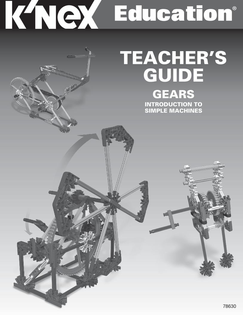
78630
TEACHER’SGUIDE
GEARSINTRODUCTION TO SIMPLE MACHINES
Education®
GEARS Teacher’s Guide
888-ABC-KNEX
INTRODUCTION�TO�SIMPLE�MACHINES
A NOTE ABOUT SAFETY:Safety is of primary concern in science and technology classrooms. It is recommended that you develop a set of rules that governs the safe, proper use of K’NEX in your classroom. Caution students to keep hands, face, hair and clothing away from all moving parts.
V3-8/14©2014 K’NEX Limited Partnership Group and its licensors.
K’NEX Limited Partnership GroupP.O. Box 700Hatfield, PA 19440-0700
K’NEX Education is a registered trademark of K’NEX Limited Partnership Group.Protected by International Copyright. All rights reserved.
Visit our website at www.knexeducation.comEmail: [email protected]: 1-888-ABC-KNEX (Toll Free)
Education®
WARNING:CHOKING HAZARD – Small parts. Not for children under 3 years.
ATTENTION :RISQUE D’ÉTOUFFEMENT – Pièces de petite taille. Ne convient pas aux enfants de moins de 3 ans.
Introduction:
1
OVERVIEWThis Teacher’s Guide has been developed to support you as your students investigate the K’NEX Intro to Simple Machines: Gears set. In conjunction with the K’NEX materials and individual student journals, the information and resources included here can be used to build your students’ understanding of scientific concepts and channel their inquiries into active and meaningful learning experiences.
K’NEX INTRO TO SIMPLE MACHINES: GearsAs part of a series, this K’NEX construction set is designed to introduce students to the scientific concepts associated with gears. Students are provided with the opportunity to acquire skills using a hands-on, inquiry-based approach to information and concepts. Working cooperatively, students are encouraged to interact with each other as they build, investigate, discuss, and evaluate scientific principles in action.
TEACHER’S GUIDEDesigned as a resource for the teacher, this guide provides a glossary of key terms and definitions, includes an overview of the concepts associated with gears, identifies student objectives for each investigation, and offers plans and scripts to successfully present selected models and their associated activities. We have also provided a selection of black line masters for your classroom use. These comprise illustrations and short definitions of some of the concepts featured in the model building activities. Most investigations can be completed in 30 to 45 minutes. Each investigation also includes a suggested extension activity, which may be used to further explore the concept that was the focus of the investigation. We recommend that teachers review their curriculum and science education standards to identify those activities that best support their academic needs.
STUDENT JOURNALSIt is expected that students will have journals available for recording observations and student responses. Students should be encouraged to enter initial thoughts at the start of an inquiry, such as inferences about possible outcomes or expository text describing what they already know about a concept or topic. Encourage students to revisit and revise their initial thoughts frequently during each investigation, until they feel confident enough to draw one or more conclusions. Students should feel comfortable consulting journal entries from other investigations within and occasionally outside the unit of focus. Their journal entries will help them make connections between the models they have built, the investigation they have conducted, and how this information is applied to real-world machines that they may use in their daily lives. Journals provide students with a place to practice drawing and labeling diagrams of systems, as well as providing a means of assessment for the Simple Machines unit. Journal Checklists are included in the Teacher’s Guide for each model and the associated inquiry activities
TABLE OF CONTENTSObjectives . . . . . . . . . . . . . . . . . . . . . . . . . . . . . . . . . . . . . . . . . . . . . . . . . . . . . . . . . . . . . . . . . . . . . . . . . . . . . . . 3
Key Terms & Definitions . . . . . . . . . . . . . . . . . . . . . . . . . . . . . . . . . . . . . . . . . . . . . . . . . . . . . . . . . . . . . . . . . . 3-4
Key Concepts . . . . . . . . . . . . . . . . . . . . . . . . . . . . . . . . . . . . . . . . . . . . . . . . . . . . . . . . . . . . . . . . . . . . . . . . . . . 4-8
The Crank Fan. . . . . . . . . . . . . . . . . . . . . . . . . . . . . . . . . . . . . . . . . . . . . . . . . . . . . . . . . . . . . . . . . . . . . . . . . . 9-18
The Car Window . . . . . . . . . . . . . . . . . . . . . . . . . . . . . . . . . . . . . . . . . . . . . . . . . . . . . . . . . . . . . . . . . . . . . . . 19-24
The Blender (with extension activities for the Eggbeater) . . . . . . . . . . . . . . . . . . . . . . . . . . . . . . . . . . . . . . . 25-30
The Stationary Bicycle . . . . . . . . . . . . . . . . . . . . . . . . . . . . . . . . . . . . . . . . . . . . . . . . . . . . . . . . . . . . . . . . . . 31-34
Blackline Masters . . . . . . . . . . . . . . . . . . . . . . . . . . . . . . . . . . . . . . . . . . . . . . . . . . . . . . . . . . . . . . . . . . . . . . 35-40
NOTE: The K’NEX Intro to Simple Machines: Gears set also includes instructions for building models of a Phonograph and a Chain Saw. These models can be used to reinforce concepts and to enhance the students’ understanding of the ways in which gear systems work.
www.knexeducat ion.com
INTRODUCTION�TO�SIMPLE�MACHINES
Education®

2This page was intentionally left blank
Wheels & AxlesGearsBackground Information
3
KEY TERMS and DEFINITIONS for the teacher. The following is intended as a resource for the teacher. The age of the students, their abilities and prior knowledge, and your curriculum requirements will determine which of these terms and definitions you introduce into your classroom activities. These terms are not presented as a list that students copy and memorize. Rather, they should be used to formalize and clarify the operational definitions your students develop during their investigations. Students should be encouraged to use the appropriate terms in context as they write about their discoveries in their journals.
Simple Machine: A simple machine is a device that transfers energy in a single motion. Simple machines make work easier by changing the way in which work is done. A simple machine does not, however, reduce the amount of work that is needed to do the job.
Force: Any kind of push or pull applied to an object.
Effort: The force that is applied to move a load or overcome a resistance (i.e. the force that is applied to do work.) The force applied to a simple machine is called input or effort force.
Resistance: The force exerted by an object against the effort force.
Work: In science, work refers to the amount of force used to move a load (object) through a given distance. Work can be defined as follows:
W = F x D Where W = work
F = the force applied to an object
D = the distance through which the force is applied
NOTE: If an object does not move, work has not been done.
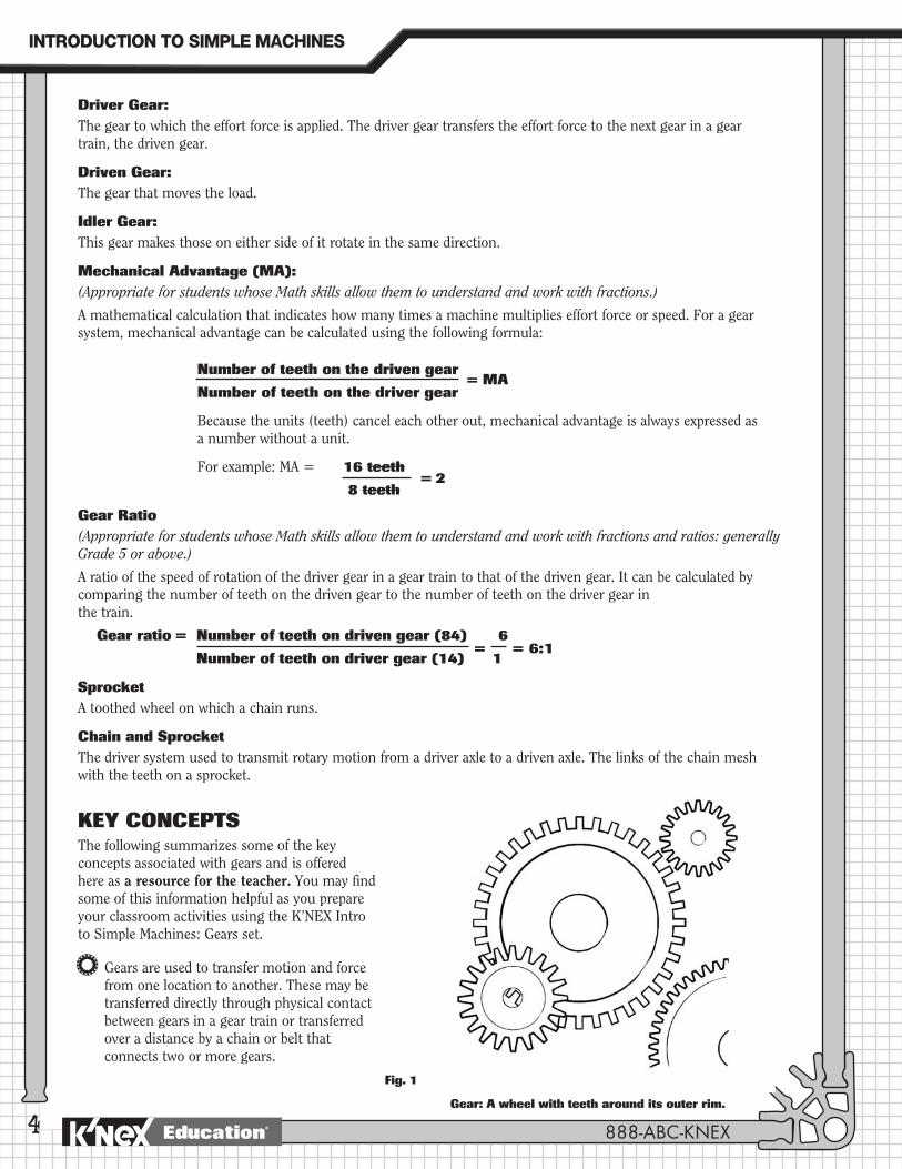
Gear:A wheel with teeth around its outer rim.
Gear Train:Two or more gears that interlock or mesh together form a gear train. As one gear turns, its teeth push against the teeth of the adjacent gear causing the second gear to turn in the opposite direction.
OBJECTIVESStudents will:1. Investigate the characteristics of gear systems to understand how they work.
2. Describe the relationships between the parts of a gear system.
3. Construct different types of gear systems and demonstrate how they function.
4. Understand how differences in gear size within a system affect speed and force output.
5. Identify how rotational motion changes into linear motion using different gear systems.
6. Identify how the use of a gear system affects work in relation to force, distance, speed, and direction.
7. Analyze objects/tools in terms of their application as gear systems.
www.knexeducat ion.com
INTRODUCTION�TO�SIMPLE�MACHINES
Education®
4
Driver Gear:The gear to which the effort force is applied. The driver gear transfers the effort force to the next gear in a gear train, the driven gear.
Driven Gear: The gear that moves the load.
Idler Gear: This gear makes those on either side of it rotate in the same direction.
Mechanical Advantage (MA): (Appropriate for students whose Math skills allow them to understand and work with fractions.)
A mathematical calculation that indicates how many times a machine multiplies effort force or speed. For a gear system, mechanical advantage can be calculated using the following formula:
Number of teeth on the driven gear
Number of teeth on the driver gear
Because the units (teeth) cancel each other out, mechanical advantage is always expressed as a number without a unit.
For example: MA = 16 teeth
8 teeth
Gear Ratio(Appropriate for students whose Math skills allow them to understand and work with fractions and ratios: generally Grade 5 or above.)
A ratio of the speed of rotation of the driver gear in a gear train to that of the driven gear. It can be calculated by comparing the number of teeth on the driven gear to the number of teeth on the driver gear in the train.
Gear ratio = Number of teeth on driven gear (84) 6
Number of teeth on driver gear (14) 1
SprocketA toothed wheel on which a chain runs.
Chain and SprocketThe driver system used to transmit rotary motion from a driver axle to a driven axle. The links of the chain mesh with the teeth on a sprocket.
KEY CONCEPTSThe following summarizes some of the key concepts associated with gears and is offered here as a resource for the teacher. You may find some of this information helpful as you prepare your classroom activities using the K’NEX Intro to Simple Machines: Gears set.
Gears are used to transfer motion and force from one location to another. These may be transferred directly through physical contact between gears in a gear train or transferred over a distance by a chain or belt that connects two or more gears.
= MA
= 2
= = 6:1
Fig. 1
Gear: A wheel with teeth around its outer rim.
888-ABC-KNEX
INTRODUCTION�TO�SIMPLE�MACHINES
Education®
5
In order to work, the teeth on gears must interlock or be connected by a chain or belt. A simple gear train comprises two or more meshed gears with only one meshed gear on each axle.
The gear wheel to which the effort is applied is called the driver gear. In the K’NEX Crank Fan model, the driver gear is the gear that is attached to the crank axle. The driver gear transmits turning forces to the driven (or follower) gear causing it to rotate in the opposite direction.
The force applied to the driver gear is the effort force or input force; the driven gear produces the output force.
Key fact about simple gear trains: In a simple gear train with two gears of the same size, the driven gear turns at the same speed as the driver gear, but in the opposite direction.
Gear systems may make work easier:Gear systems can make work easier by making things easier to move. They can do this in the following ways:
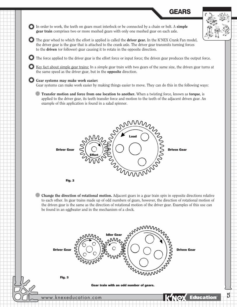
Transfer motion and force from one location to another. When a twisting force, known as torque, is applied to the driver gear, its teeth transfer force and motion to the teeth of the adjacent driven gear. An example of this application is found in a salad spinner.
Driver Gear Driven Gear
Idler Gear
Gear train with an odd number of gears.
Change the direction of rotational motion. Adjacent gears in a gear train spin in opposite directions relative to each other. In gear trains made up of odd numbers of gears, however, the direction of rotational motion of the driven gear is the same as the direction of rotational motion of the driver gear. Examples of this use can be found in an eggbeater and in the mechanism of a clock.
Effort
Load
Driver Gear Driven Gear
Fig. 2
Fig. 3
GEARS
www.knexeducat ion.com Education®
6
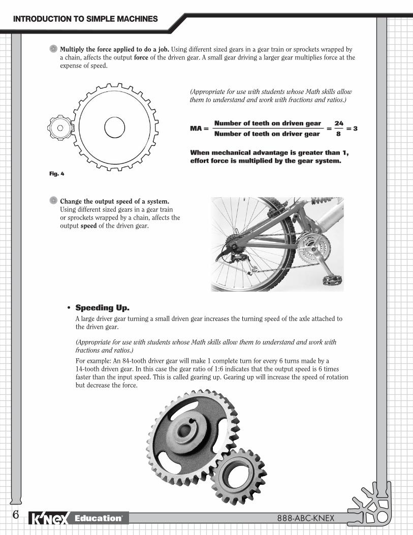
Multiply the force applied to do a job. Using different sized gears in a gear train or sprockets wrapped by a chain, affects the output force of the driven gear. A small gear driving a larger gear multiplies force at the expense of speed.
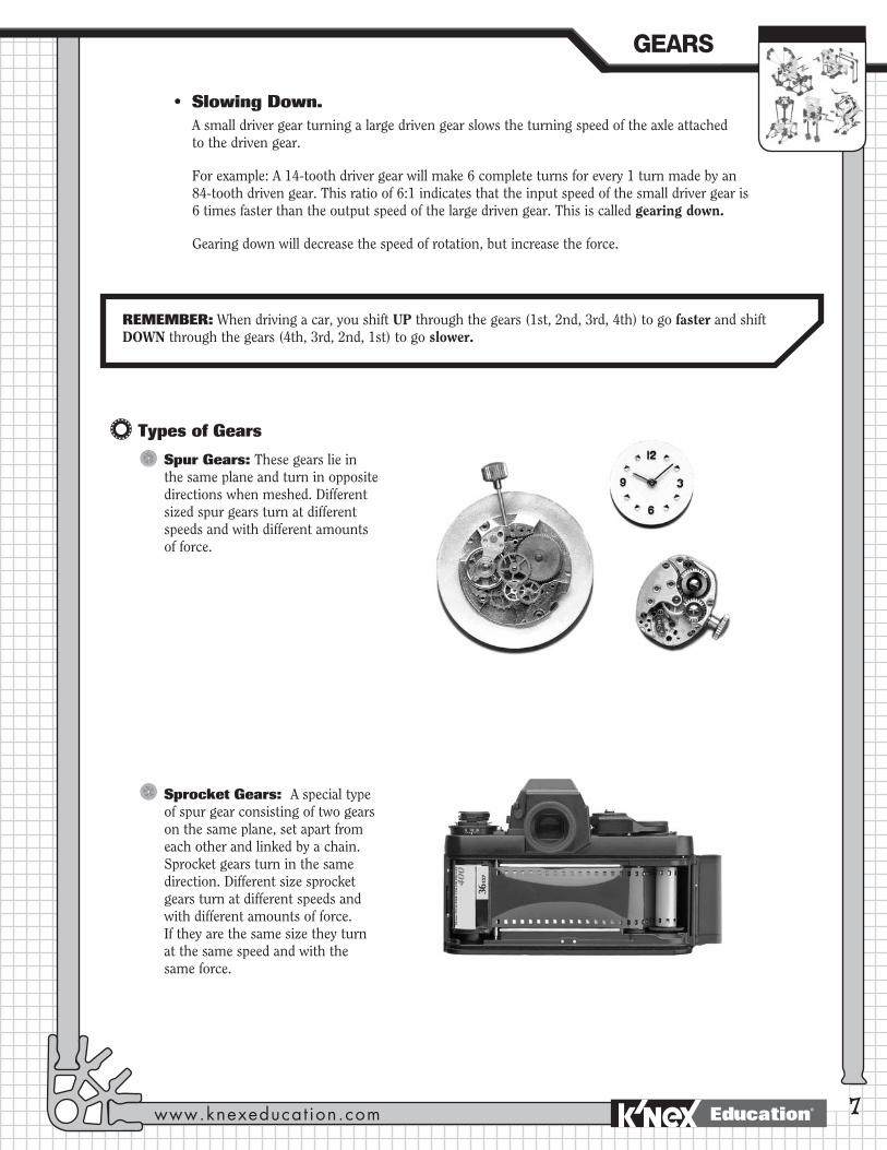
Change the output speed of a system. Using different sized gears in a gear train or sprockets wrapped by a chain, affects the output speed of the driven gear.
• SpeedingUp.A large driver gear turning a small driven gear increases the turning speed of the axle attached to the driven gear.
(Appropriate for use with students whose Math skills allow them to understand and work with fractions and ratios.)
For example: An 84-tooth driver gear will make 1 complete turn for every 6 turns made by a 14-tooth driven gear. In this case the gear ratio of 1:6 indicates that the output speed is 6 times faster than the input speed. This is called gearing up. Gearing up will increase the speed of rotation but decrease the force.
Number of teeth on driven gear 24
Number of teeth on driver gear 8
When mechanical advantage is greater than 1, effort force is multiplied by the gear system.
= = 3MA =
Fig. 4
(Appropriate for use with students whose Math skills allow them to understand and work with fractions and ratios.)
888-ABC-KNEX
INTRODUCTION�TO�SIMPLE�MACHINES
Education®
7
• SlowingDown.A small driver gear turning a large driven gear slows the turning speed of the axle attached to the driven gear.
For example: A 14-tooth driver gear will make 6 complete turns for every 1 turn made by an 84-tooth driven gear. This ratio of 6:1 indicates that the input speed of the small driver gear is 6 times faster than the output speed of the large driven gear. This is called gearing down.
Gearing down will decrease the speed of rotation, but increase the force.
Types of Gears
Spur Gears: These gears lie in the same plane and turn in opposite directions when meshed. Different sized spur gears turn at different speeds and with different amounts of force.
Sprocket Gears: A special type of spur gear consisting of two gears on the same plane, set apart from each other and linked by a chain. Sprocket gears turn in the same direction. Different size sprocket gears turn at different speeds and with different amounts of force. If they are the same size they turn at the same speed and with the same force.
REMEMBER: When driving a car, you shift UP through the gears (1st, 2nd, 3rd, 4th) to go faster and shift DOWN through the gears (4th, 3rd, 2nd, 1st) to go slower.
GEARS
www.knexeducat ion.com Education®
8
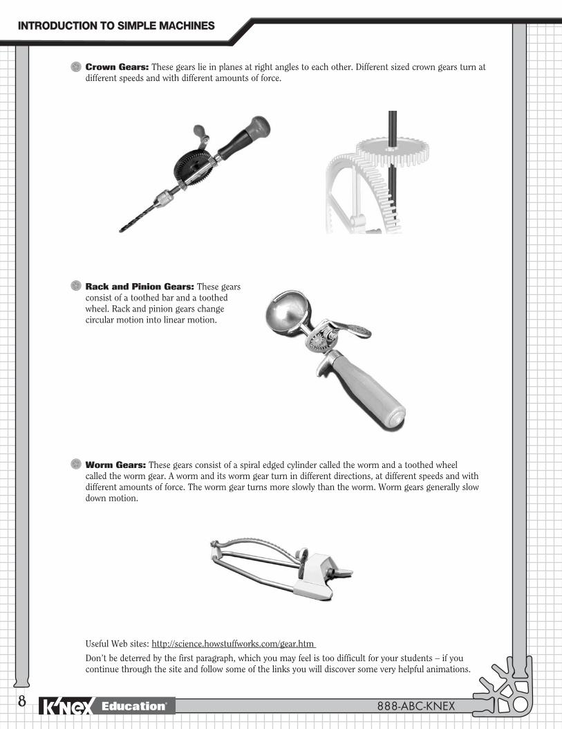
Crown Gears: These gears lie in planes at right angles to each other. Different sized crown gears turn at different speeds and with different amounts of force.
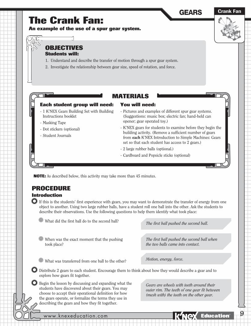
Rack and Pinion Gears: These gears consist of a toothed bar and a toothed wheel. Rack and pinion gears change circular motion into linear motion.
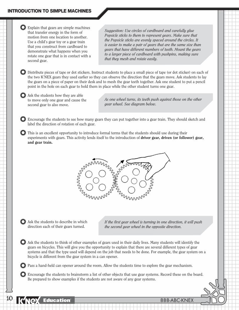
Worm Gears: These gears consist of a spiral edged cylinder called the worm and a toothed wheel called the worm gear. A worm and its worm gear turn in different directions, at different speeds and with different amounts of force. The worm gear turns more slowly than the worm. Worm gears generally slow down motion.
Useful Web sites: http://science.howstuffworks.com/gear.htm
Don’t be deterred by the first paragraph, which you may feel is too difficult for your students – if you continue through the site and follow some of the links you will discover some very helpful animations.
888-ABC-KNEX
INTRODUCTION�TO�SIMPLE�MACHINES
Education®
The Crank Fan: An example of the use of a spur gear system.
Crank Fan
9
PROCEDUREIntroduction
If this is the students’ first experience with gears, you may want to demonstrate the transfer of energy from one object to another. Using two large rubber balls, have a student roll one ball into the other. Ask the students to describe their observations. Use the following questions to help them identify what took place:
What did the first ball do to the second ball?
When was the exact moment that the pushing took place?
What was transferred from one ball to the other?
Distribute 2 gears to each student. Encourage them to think about how they would describe a gear and to explore how gears fit together.
Begin the lesson by discussing and expanding what the students have discovered about their gears. You may choose to accept their operational definition for how the gears operate, or formalize the terms they use in describing the gears and how they fit together.
OBJECTIVESStudents will:1. Understand and describe the transfer of motion through a spur gear system.
2. Investigate the relationship between gear size, speed of rotation, and force.
MATERIALSEach student group will need: - 1 K’NEX Gears Building Set with Building
Instructions booklet
- Masking Tape
- Dot stickers (optional)
- Student Journals
You will need:- Pictures and examples of different spur gear systems.
(Suggestions: music box; electric fan; hand-held can opener; gear operated toy.)
- K’NEX gears for students to examine before they begin the building activity. (Remove a sufficient number of gears from each K’NEX Introduction to Simple Machines: Gears set so that each student has access to 2 gears.)
- 2 large rubber balls (optional.)
- Cardboard and Popsicle sticks (optional)
NOTE: As described below, this activity may take more than 45 minutes.
The first ball pushed the second ball.
The first ball pushed the second ball when the two balls came into contact.
Gears are wheels with teeth around their outer rim. The teeth of one gear fit between (mesh with) the teeth on the other gear.
Motion, energy, force.
GEARS
www.knexeducat ion.com Education®
10
Explain that gears are simple machines that transfer energy in the form of motion from one location to another. Use a child’s gear toy or a gear train that you construct from cardboard to demonstrate what happens when you rotate one gear that is in contact with a second gear.
Distribute pieces of tape or dot stickers. Instruct students to place a small piece of tape (or dot sticker) on each of the two K’NEX gears they used earlier so they can observe the direction that the gears move. Ask students to lay the gears on a piece of paper on their desk and to mesh the gear teeth together. Ask one student to put a pencil point in the hole on each gear to hold them in place while the other student turns one gear.
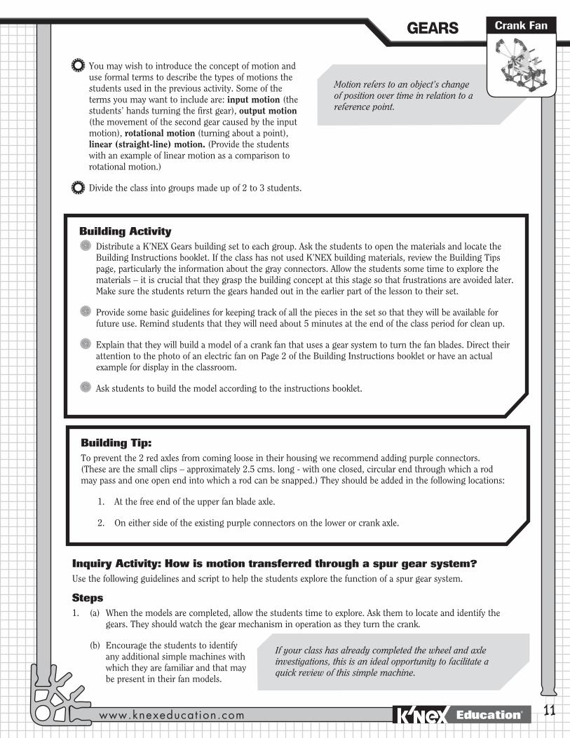
Ask the students how they are able to move only one gear and cause the second gear to also move.
Encourage the students to see how many gears they can put together into a gear train. They should sketch and label the direction of rotation of each gear.
This is an excellent opportunity to introduce formal terms that the students should use during their experiments with gears. This activity lends itself to the introduction of driver gear, driven (or follower) gear, and gear train.
Ask the students to describe in which direction each of their gears turned.
Ask the students to think of other examples of gears used in their daily lives. Many students will identify the gears on bicycles. This will give you the opportunity to explain that there are several different types of gear systems and that the type used will depend on the job that needs to be done. For example, the gear system on a bicycle is different from the gear system in a can opener.
Pass a hand-held can opener around the room. Allow the students time to explore the gear mechanism.
Encourage the students to brainstorm a list of other objects that use gear systems. Record these on the board. Be prepared to show examples if the students are not aware of any gear systems.
Suggestion: Use circles of cardboard and carefully glue Popsicle sticks to them to represent gears. Make sure that the Popsicle sticks are evenly spaced around the circles. It is easier to make a pair of gears that are the same size than gears that have different numbers of teeth. Mount the gears to a larger piece of cardboard with pushpins, making sure that they mesh and rotate easily.
As one wheel turns, its teeth push against those on the other gear wheel. See diagram below.
If the first gear wheel is turning in one direction, it will push the second gear wheel in the opposite direction.
888-ABC-KNEX
INTRODUCTION�TO�SIMPLE�MACHINES
Education®
You may wish to introduce the concept of motion and use formal terms to describe the types of motions the students used in the previous activity. Some of the terms you may want to include are: input motion (the students’ hands turning the first gear), output motion (the movement of the second gear caused by the input motion), rotational motion (turning about a point), linear (straight-line) motion. (Provide the students with an example of linear motion as a comparison to rotational motion.)
Divide the class into groups made up of 2 to 3 students.
Inquiry Activity: How is motion transferred through a spur gear system?Use the following guidelines and script to help the students explore the function of a spur gear system.
Steps1. (a) When the models are completed, allow the students time to explore. Ask them to locate and identify the
gears. They should watch the gear mechanism in operation as they turn the crank.
(b) Encourage the students to identify any additional simple machines with which they are familiar and that may be present in their fan models.
Motion refers to an object’s change of position over time in relation to a reference point.
11
Building ActivityDistribute a K’NEX Gears building set to each group. Ask the students to open the materials and locate the Building Instructions booklet. If the class has not used K’NEX building materials, review the Building Tips page, particularly the information about the gray connectors. Allow the students some time to explore the materials – it is crucial that they grasp the building concept at this stage so that frustrations are avoided later. Make sure the students return the gears handed out in the earlier part of the lesson to their set.
Provide some basic guidelines for keeping track of all the pieces in the set so that they will be available for future use. Remind students that they will need about 5 minutes at the end of the class period for clean up.
Explain that they will build a model of a crank fan that uses a gear system to turn the fan blades. Direct their attention to the photo of an electric fan on Page 2 of the Building Instructions booklet or have an actual example for display in the classroom.
Ask students to build the model according to the instructions booklet.
Building Tip:To prevent the 2 red axles from coming loose in their housing we recommend adding purple connectors. (These are the small clips – approximately 2.5 cms. long - with one closed, circular end through which a rod may pass and one open end into which a rod can be snapped.) They should be added in the following locations:
1. At the free end of the upper fan blade axle.
2. On either side of the existing purple connectors on the lower or crank axle.
If your class has already completed the wheel and axle investigations, this is an ideal opportunity to facilitate a quick review of this simple machine.
Crank FanGEARS
www.knexeducat ion.com Education®
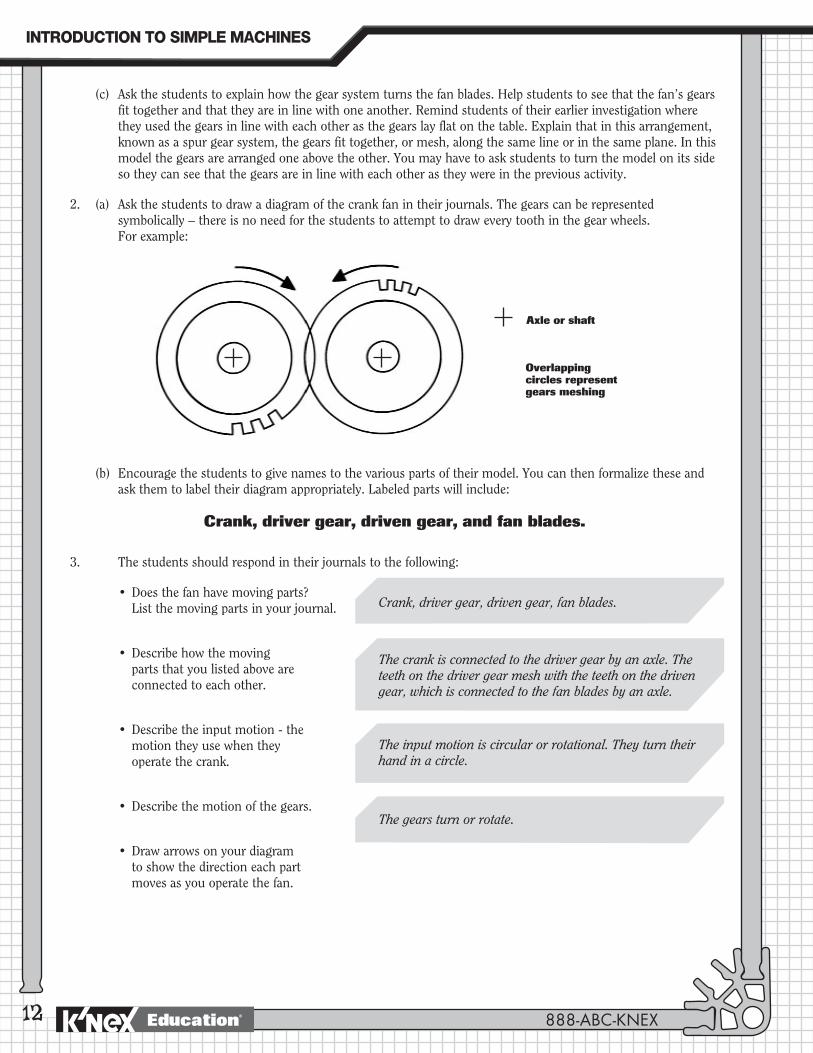
(b) Encourage the students to give names to the various parts of their model. You can then formalize these and ask them to label their diagram appropriately. Labeled parts will include:
Crank, driver gear, driven gear, and fan blades.
3. The students should respond in their journals to the following:
•Doesthefanhavemovingparts? List the moving parts in your journal.
•Describehowthemovingparts that you listed above are connected to each other.
•Describetheinputmotion-themotion they use when they operate the crank.
•Describethemotionofthegears.
• Drawarrowsonyourdiagramto show the direction each part moves as you operate the fan.
12
Axle or shaft
Overlapping circles represent gears meshing
(c) Ask the students to explain how the gear system turns the fan blades. Help students to see that the fan’s gears fit together and that they are in line with one another. Remind students of their earlier investigation where they used the gears in line with each other as the gears lay flat on the table. Explain that in this arrangement, known as a spur gear system, the gears fit together, or mesh, along the same line or in the same plane. In this model the gears are arranged one above the other. You may have to ask students to turn the model on its side so they can see that the gears are in line with each other as they were in the previous activity.
2. (a) Ask the students to draw a diagram of the crank fan in their journals. The gears can be represented symbolically – there is no need for the students to attempt to draw every tooth in the gear wheels. For example:
The crank is connected to the driver gear by an axle. The teeth on the driver gear mesh with the teeth on the driven gear, which is connected to the fan blades by an axle.
Crank, driver gear, driven gear, fan blades.
The gears turn or rotate.
The input motion is circular or rotational. They turn their hand in a circle.
888-ABC-KNEX
INTRODUCTION�TO�SIMPLE�MACHINES
Education®
13
4. Ask the students to attach a small piece of masking tape to the edge of one fan blade and ask them to select a reference point so they can keep track of the fan blade as it rotates. Encourage them to turn the crank.
(a) Ask the students to turn the crank to make one rotation. Have them continue turning the crank but they should vary the speed at which it is turned.
Ask them how they can make the fan turn faster/slower.
(b) Suggest that they mark the two gear wheels with either a dot sticker or with a pencil mark. The marks should be made at the point where the two gears mesh. Then ask them to make one slow turn of the crank. What do they notice?
(c) Students should note in their journals the sizes of the two gears - driver and driven – used in the model.
(d) Do they think there could be a relationship between the size of the gears and their findings to (b) above?
(e) Ask the students to turn the crank one additional turn, but this time, ask them to notice how far the fan blades travel. One student should count the number of times the blade with the masking tape passes the selected reference point, while the other should focus on making just one full turn with the crank.
(f) How easy/hard is it to turn the crank with this gear arrangement?
(g) Ask them to summarize what their observations show concerning the distance the two gears and the fan blades turn with one rotation of the crank.
Students should observe that the speed of the fan was entirely dependent upon the speed at which the crank was turned.
The students should be helped to understand that these two gears, that are the same size and meshed together, rotate at the same speed even though they are on different axles.
Note: This will generate subjective responses, but will help the students make comparisons when they explore other gear arrangements for the model.
Students should notice that all the moving parts rotate once with one turn of the crank.
BOTH gears make one complete rotation with one turn of the crank.
The fan blades also make one complete turn with one turn of the crank.
They are the same size.
Crank FanGEARS
www.knexeducat ion.com Education®
14
NOTE: We recommend that 2 groups work together for Step 5 below. One group should build the model with the large gear as the driver, and the other group should build the version of the model with the small gear as the driver. Having both models available will make comparisons easier.
5. (a) Ask the students to speculate what they think will happen if they use
(i) a large gear wheel to drive a small gear wheel and
(ii) a small gear wheel to drive a large gear wheel.
They should make a note of their responses in their journals.
(b) Encourage the students to discover if their predictions were correct by rebuilding their models using two gears that are different in size. They should use the diagrams on the right hand side of Page 3 of the Building Instructions booklet as a guide.
(c) Ask them to think of a way to compare the speed that the fan turns, with the speed of the crank when the big gear is attached to the crank and the small gear is attached to the fan blades.
(d) How easy/hard is it to turn the crank with this arrangement compared to when the gears were the same size?
All their observations should be recorded in their journals.
(e) Students should then compare the speed at which the fan turns with the speed of the crank, when the small gear is attached to the crank axle and the big gear is attached to the fan blade’s axle.
(f) How easy/hard is it to turn the crank with this arrangement, compared to when the gears were (i) the same size and (ii) the large gear was the driver?
Observations should be recorded in their journals.
6. (a) Discuss their observations of gear systems using different sized gears.
(b) Ask the students if their observations support the prediction that they each wrote earlier. Encourage the students to support their conclusions using evidence from their investigations.
Use the technique adopted in Step 4 - put a piece of masking tape on one fan blade and observe where it is before a turn of the crank and then notice how many times the tape passes that same point when the crank is turned one time.
Students should observe that when the small gear drives the big gear, the fan turns more slowly than the crank: it takes 6 turns of the crank for the fan blades to make 1 complete rotation. The crank, however, is easier to turn than in either of the other 2 gear arrangements.
Students should observe that when the big gear drives the small gear, the fan turns more quickly than the crank: 1 turn of the crank results in approximately 6 turns of the fan blades. The crank, however, is harder to turn than it was when the model had both gears the same size.
888-ABC-KNEX
INTRODUCTION�TO�SIMPLE�MACHINES
Education®
Applying The IdeaReview the findings of Step 3 with the class:
Did the crank and the gear on its axle move at the same speed?
Did you notice the same results when you used a smaller gear? A larger gear?
When you operated the fan using two gears that were the same size, which of these statements was true?
The driver gear turned faster than the driven gear?
The driven gear turned faster than the driver gear?
They both turned at the same speed.
Ask the class to summarize these findings about the fan with the same sized gears by completing the following sentences:
Gears that are on the same axle rotate at the
__________________ __________________
Gears that mesh and are the same size rotate at the
__________________ __________________
In this crank fan all the moving parts rotate at the
__________________ __________________
because the driver gear and the driven gear are the
__________________ __________________
Ask the students to record the advantages and disadvantages of the 2 different gear systems they investigated in Step 4.
Encourage the students to discuss situations where each gear system would be most useful. Encourage them to include “effort force,” “driver gear,” and “driven gear” in their responses.
15
They move at the same speed: one turn of the crank (wheel) causes the gear on the same axle to rotate once.
Yes. Even when gears are a different size, if they are on the same axle they will rotate at the same speed.
They turned at the same speed: one rotation of the driver gear turned the driven gear through one rotation.
same speed
same speed
same speed; same size
Turning the crank was easier when the small gear turned the large gear. However, the fan turned more slowly than the crank. Although the crank was harder to turn when the large gear turned the small gear, the fan blades turned much faster than the crank.
Answers will vary. Possible answer: A small gear turning a large gear would be most useful if the object that must be turned is heavy. Turning a large, heavy object would need less effort force when the driver gear is smaller than the driven gear.
Crank FanGEARS
www.knexeducat ion.com Education®
16
Extending The Idea(Suggested grade levels are indicated.)
[Grades: 3-4.]1. Suggest that the students search the Internet for additional information about gear systems. They could
conduct a Google® search using the key word: “gear.”
[Grade: 5.]2. (a) Remind the students that they used a crude measurement to compare the input and output speeds of the
gear wheels when they completed Steps 4(e), 5(c), and 5(e). Explain that what they discovered was a simple Gear Ratio.
(b) Explain that a more accurate approach is to compare results by counting the number of teeth on each gear wheel. Write the equation for the Gear Ratio on the blackboard, dry board, or overhead projector so that it is visible from any location in the classroom.
Number of teeth on the driven (follower) gear
Number of teeth on the driver gear
For example: 14/84 gives a gear ratio of 1/6 or 1:6
Explain that a 1:6 gear ratio means that for every complete revolution of the driver gear, the driven gear makes 6 complete revolutions. Or, said another way: the output speed is faster than the input speed.
[Grades: 3-5.]3. (a) Ask all the student groups to remove the fan blades from their crank fans and set them aside.
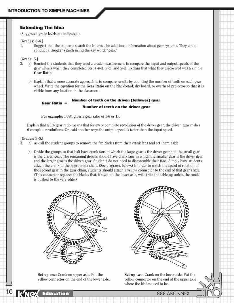
(b) Divide the groups so that half have crank fans in which the large gear is the driver gear and the small gear is the driven gear. The remaining groups should have crank fans in which the smaller gear is the driver gear and the larger gear is the driven gear. Students do not need to disassemble their fans. Simply have students attach the crank to the appropriate shaft. (See diagrams below.) In order to watch the speed of rotation of the second gear in the gear chain, students should attach a yellow connector to the end of that gear’s axle. (This connector replaces the blades that, if used on the lower axle, will strike the tabletop unless the model is pushed to the very edge.)
Gear Ratio =
Set-up one: Crank on upper axle. Put the yellow connector on the end of the lower axle.
Set-up two: Crank on the lower axle. Put the yellow connector on the end of the upper axle where the blades used to be.
888-ABC-KNEX
INTRODUCTION�TO�SIMPLE�MACHINES
Education®
17
[Grade: 5.] (c) Ask the students to determine the gear ratio of their crank fan. Students should write the gear
ratio in their journals and describe, in their own words, what the gear ratio means in reference to their crank fan.
(d) Encourage the students to tell you what is gained by using this gear train. If students need clarification, ask them whether their fan turns quickly or slowly. You can then take this opportunity to help the students understand they cannot use a machine to gain both speed and force. They can gain speed at the expense of force or gain force at the expense of speed. If you decide to include this there is space provided in the chart below for students to record their findings.
[Grade: 5.]4. The groups should exchange fans and repeat Step (d) above.
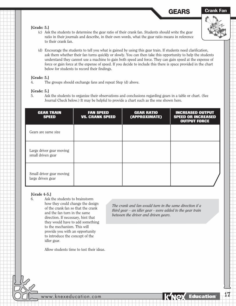
[Grade: 5.]5. Ask the students to organize their observations and conclusions regarding gears in a table or chart. (See
Journal Check below.) It may be helpful to provide a chart such as the one shown here.
[Grade 4-5.]6. Ask the students to brainstorm
how they could change the design of the crank fan so that the crank and the fan turn in the same direction. If necessary, hint that they would have to add something to the mechanism. This will provide you with an opportunity to introduce the concept of the idler gear.
Allow students time to test their ideas.
Gears are same size
Large driver gear moving small driven gear
Small driver gear moving large driven gear
GEAR TRAIN FAN SPEED GEAR RATIO INCREASED OUTPUT SPEED VS. CRANK SPEED (APPROXIMATE) SPEED OR INCREASED OUTPUT FORCE
The crank and fan would turn in the same direction if a third gear – an idler gear - were added to the gear train between the driver and driven gears.
Crank FanGEARS
www.knexeducat ion.com Education®
18
JOURNAL CHECK: Students should keep individual journals to record their findings. The following are examples of the types of items that could appear in each student’s journal:
4 Diagram of crank fan including labels and arrows.
4 Record of student observations.
4 Predictions.
4 Conclusions.
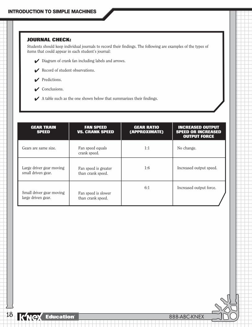
4 A table such as the one shown below that summarizes their findings.
Gears are same size.
Large driver gear moving small driven gear.
Small driver gear moving large driven gear.
Fan speed equals crank speed.
Fan speed is greater than crank speed.
Fan speed is slower than crank speed.
1:1
1:6
6:1
No change.
Increased output speed.
Increased output force.
GEAR TRAIN FAN SPEED GEAR RATIO INCREASED OUTPUT SPEED VS. CRANK SPEED (APPROXIMATE) SPEED OR INCREASED OUTPUT FORCE
888-ABC-KNEX
INTRODUCTION�TO�SIMPLE�MACHINES
Education®
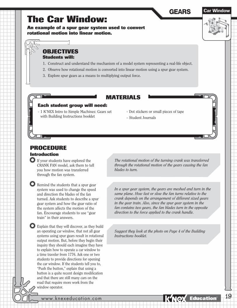
The Car Window: An example of a spur gear system used to convert rotational motion into linear motion.
Car Window
19
PROCEDUREIntroduction
If your students have explored the CRANK FAN model, ask them to tell you how motion was transferred through the fan system.
Remind the students that a spur gear system was used to change the speed and direction the blades of the fan turned. Ask students to describe a spur gear system and how the gear ratio of the system affects the motion of the fan. Encourage students to use “gear train” in their answers.
Explain that they will discover, as they build an operating car window, that not all gear systems using spur gears result in rotational output motion. But, before they begin their inquiry they should each imagine they have to explain how to operate a car window to a time traveler from 1776. Ask one or two students to provide directions for opening the car window. If the students tell you to, “Push the button,” explain that using a button is a quite recent design modification and that there are still many cars on the road that require more work from the window operator.
OBJECTIVESStudents will:1. Construct and understand the mechanism of a model system representing a real-life object.
2. Observe how rotational motion is converted into linear motion using a spur gear system.
3. Explore spur gears as a means to multiplying output force.
MATERIALSEach student group will need: - 1 K’NEX Intro to Simple Machines: Gears set
with Building Instructions booklet- Dot stickers or small pieces of tape
- Student Journals
The rotational motion of the turning crank was transferred through the rotational motion of the gears causing the fan blades to turn.
In a spur gear system, the gears are meshed and turn in the same plane. How fast or slow the fan turns relative to the crank depends on the arrangement of different sized gears in the gear train. Also, since the spur gear system in the fan contains two gears, the fan blades turn in the opposite direction to the force applied to the crank handle.
Suggest they look at the photo on Page 4 of the Building Instructions booklet.
GEARS
www.knexeducat ion.com Education®
20
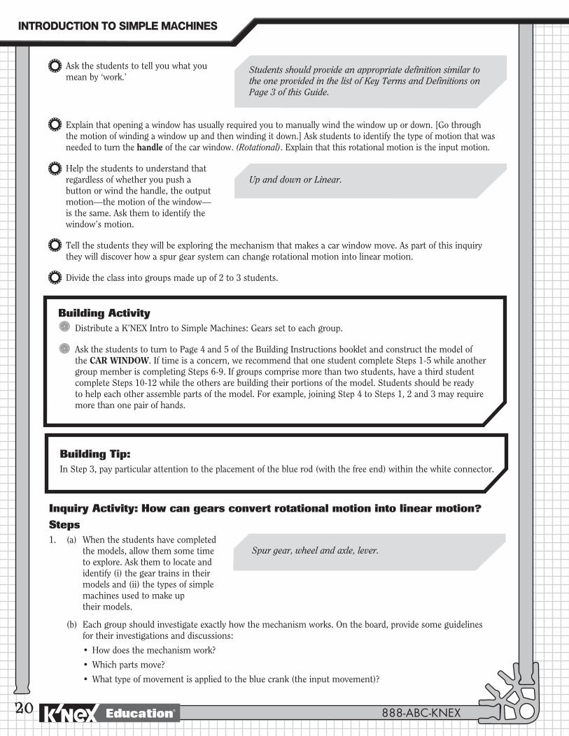
Ask the students to tell you what you mean by ‘work.’
Explain that opening a window has usually required you to manually wind the window up or down. [Go through the motion of winding a window up and then winding it down.] Ask students to identify the type of motion that was needed to turn the handle of the car window. (Rotational). Explain that this rotational motion is the input motion.
Help the students to understand that regardless of whether you push a button or wind the handle, the output motion—the motion of the window—is the same. Ask them to identify the window’s motion.
Tell the students they will be exploring the mechanism that makes a car window move. As part of this inquiry they will discover how a spur gear system can change rotational motion into linear motion.
Divide the class into groups made up of 2 to 3 students.
Students should provide an appropriate definition similar to the one provided in the list of Key Terms and Definitions on Page 3 of this Guide.
Up and down or Linear.
Building ActivityDistribute a K’NEX Intro to Simple Machines: Gears set to each group.
Ask the students to turn to Page 4 and 5 of the Building Instructions booklet and construct the model of the CAR WINDOW. If time is a concern, we recommend that one student complete Steps 1-5 while another group member is completing Steps 6-9. If groups comprise more than two students, have a third student complete Steps 10-12 while the others are building their portions of the model. Students should be ready to help each other assemble parts of the model. For example, joining Step 4 to Steps 1, 2 and 3 may require more than one pair of hands.
Building Tip:In Step 3, pay particular attention to the placement of the blue rod (with the free end) within the white connector.
Inquiry Activity: How can gears convert rotational motion into linear motion?Steps1. (a) When the students have completed
the models, allow them some time to explore. Ask them to locate and identify (i) the gear trains in their models and (ii) the types of simple machines used to make up their models.
(b) Each group should investigate exactly how the mechanism works. On the board, provide some guidelines for their investigations and discussions:
•Howdoesthemechanismwork?
•Whichpartsmove?
•Whattypeofmovementisappliedtothebluecrank(theinputmovement)?
Spur gear, wheel and axle, lever.
888-ABC-KNEX
INTRODUCTION�TO�SIMPLE�MACHINES
Education®
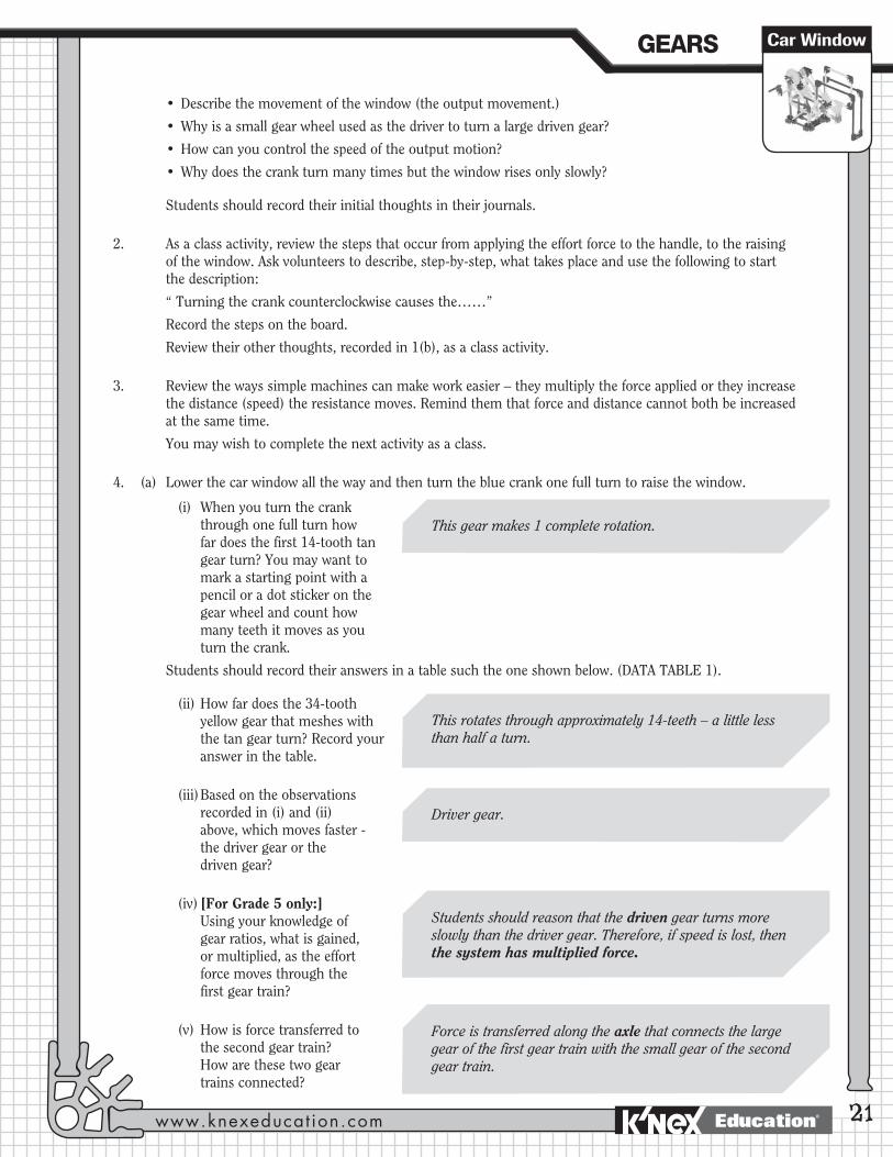
•Describethemovementofthewindow(theoutputmovement.)
•Whyisasmallgearwheelusedasthedrivertoturnalargedrivengear?
•Howcanyoucontrolthespeedoftheoutputmotion?
•Whydoesthecrankturnmanytimesbutthewindowrisesonlyslowly?
Students should record their initial thoughts in their journals.
2. As a class activity, review the steps that occur from applying the effort force to the handle, to the raising of the window. Ask volunteers to describe, step-by-step, what takes place and use the following to start the description:
“ Turning the crank counterclockwise causes the……”
Record the steps on the board.
Review their other thoughts, recorded in 1(b), as a class activity.
3. Review the ways simple machines can make work easier – they multiply the force applied or they increase the distance (speed) the resistance moves. Remind them that force and distance cannot both be increased at the same time.
You may wish to complete the next activity as a class.
4. (a) Lower the car window all the way and then turn the blue crank one full turn to raise the window.
(i) When you turn the crank through one full turn how far does the first 14-tooth tan gear turn? You may want to mark a starting point with a pencil or a dot sticker on the gear wheel and count how many teeth it moves as you turn the crank.
Students should record their answers in a table such the one shown below. (DATA TABLE 1).
(ii) How far does the 34-tooth yellow gear that meshes with the tan gear turn? Record your answer in the table.
(iii) Based on the observations recorded in (i) and (ii) above, which moves faster - the driver gear or the driven gear?
(iv) [For Grade 5 only:] Using your knowledge of
gear ratios, what is gained, or multiplied, as the effort force moves through the first gear train?
(v) How is force transferred to the second gear train? How are these two gear trains connected?
21
This rotates through approximately 14-teeth – a little less than half a turn.
Students should reason that the driven gear turns more slowly than the driver gear. Therefore, if speed is lost, then the system has multiplied force.
Force is transferred along the axle that connects the large gear of the first gear train with the small gear of the second gear train.
Driver gear.
This gear makes 1 complete rotation.
Car WindowGEARS
www.knexeducat ion.com Education®
22
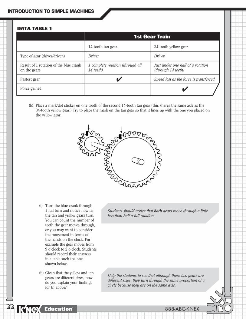
Type of gear (driver/driven)
Result of 1 rotation of the blue crank on the gears
Fastest gear
Force gained
14-tooth tan gear
Driver
1 complete rotation (through all 14 teeth)
4
34-tooth yellow gear
Driven
Just under one half of a rotation (through 14 teeth)
Speed lost as the force is transferred
4
DATA TABLE 1
1st Gear Train
(b) Place a mark/dot sticker on one tooth of the second 14-tooth tan gear (this shares the same axle as the 34-tooth yellow gear.) Try to place the mark on the tan gear so that it lines up with the one you placed on the yellow gear.
(i) Turn the blue crank through 1 full turn and notice how far the tan and yellow gears turn. You can count the number of teeth the gear moves through, or you may want to consider the movement in terms of the hands on the clock. For example the gear moves from 9 o’clock to 2 o’clock. Students should record their answers in a table such the one shown below.
(ii) Given that the yellow and tan gears are different sizes, how do you explain your findings for (i) above?
Students should notice that both gears move through a little less than half a full rotation.
Help the students to see that although these two gears are different sizes, they turn through the same proportion of a circle because they are on the same axle.
888-ABC-KNEX
INTRODUCTION�TO�SIMPLE�MACHINES
Education®
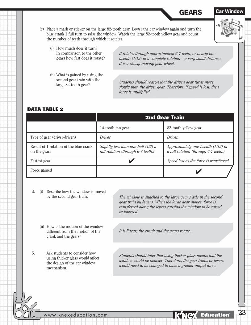
(c) Place a mark or sticker on the large 82-tooth gear. Lower the car window again and turn the blue crank 1 full turn to raise the window. Watch the large 82-tooth yellow gear and count the number of teeth through which it rotates.
(i) How much does it turn? In comparison to the other gears how fast does it rotate?
(ii) What is gained by using the second gear train with the large 82-tooth gear?
d. (i) Describe how the window is moved by the second gear train.
(ii) How is the motion of the window different from the motion of the crank and the gears?
5. Ask students to consider how using thicker glass would affect the design of the car window mechanism.
23
It rotates through approximately 6-7 teeth, or nearly one twelfth (1/12) of a complete rotation – a very small distance. It is a slowly moving gear wheel.
Students should reason that the driven gear turns more slowly than the driver gear. Therefore, if speed is lost, then force is multiplied.
The window is attached to the large gear’s axle in the second gear train by levers. When the large gear moves, force is transferred along the levers causing the window to be raised or lowered.
Students should infer that using thicker glass means that the window would be heavier. Therefore, the gear trains or levers would need to be changed to have a greater output force.
It is linear; the crank and the gears rotate.
Type of gear (driver/driven)
Result of 1 rotation of the blue crank on the gears
Fastest gear
Force gained
14-tooth tan gear
Driver
Slightly less than one-half (1/2) a full rotation (through 6-7 teeth.)
4
82-tooth yellow gear
Driven
Approximately one-twelfth (1/12) of a full rotation (through 6-7 teeth.)
Speed lost as the force is transferred
4
DATA TABLE 2
2nd Gear Train
Car WindowGEARS
www.knexeducat ion.com Education®
24
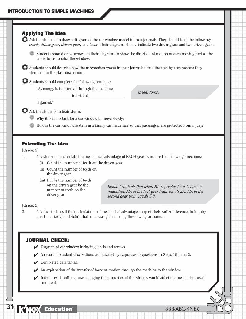
Applying The IdeaAsk the students to draw a diagram of the car window model in their journals. They should label the following: crank, driver gear, driven gear, and lever. Their diagrams should indicate two driver gears and two driven gears.
Students should draw arrows on their diagrams to show the direction of motion of each moving part as the crank turns to raise the window.
Students should describe how the mechanism works in their journals using the step-by-step process they identified in the class discussion.
Students should complete the following sentence:
“As energy is transferred through the machine,
__________________ is lost but __________________
is gained.”
Ask the students to brainstorm:
Why it is important for a car window to move slowly?
How is the car window system in a family car made safe so that passengers are protected from injury?
Extending The Idea[Grade: 5]
1. Ask students to calculate the mechanical advantage of EACH gear train. Use the following directions:
(i) Count the number of teeth on the driven gear.
(ii) Count the number of teeth on the driver gear.
(iii) Divide the number of teeth on the driven gear by the number of teeth on the driver gear.
[Grade: 5]
2. Ask the students if their calculations of mechanical advantage support their earlier inference, in Inquiry questions 4a(iv) and 4c(ii), that force was gained using these two gear trains.
Remind students that when MA is greater than 1, force is multiplied. MA of the first gear train equals 2.4. MA of the second gear train equals 5.8.
speed; force.
JOURNAL CHECK: 4 Diagram of car window including labels and arrows
4 A record of student observations as indicated by responses to questions in Steps 1(b) and 3.
4 Completed data tables.
4 An explanation of the transfer of force or motion through the machine to the window.
4 Inferences describing how changing the properties of the window would affect the mechanism used to raise it.
888-ABC-KNEX
INTRODUCTION�TO�SIMPLE�MACHINES
Education®
The Blender: An example of a crown gear system.
Blender
25
PROCEDUREIntroduction
Ask the students to describe how motion was transferred through a spur gear system.
If your students have completed the CRANK FAN activity, review how a spur gear system can make work easier by changing output speed or multiplying output force. Help the students understand that they cannot use a machine to gain both speed and force. Explain that there is always a trade-off when they use a simple machine. They can gain speed at the expense of force or gain force at the expense of speed. Ask the students to describe what is gained when a gear system uses the same sized gears in a gear train.
Explain that a spur gear system is just one type of gear arrangement. Tell the students that they will explore the gear mechanism used in a blender. The arrangement of gears in a blender differs from that used in a crank fan. Their model blender will be hand operated.
NOTE: In Extending the Idea you will find building and associated activities for the EGGBEATER model. (See Pages 10 and 11 of the Building Instructions booklet.)
OBJECTIVESStudents will:1. Construct and investigate the mechanism of a model system that represents a
real-life object.
2. Observe how rotational motion is transferred from one plane to another using a crown gear system.
MATERIALSEach student group will need: - 1 K’NEX Gears Building Set with Building
Instructions booklet
- Student Journals
You will need: - A blender + food for demonstration purposes
Force and motion are transferred from one gear to another along the same plane.
Students should remember from the Crank Fan activity that when gears are the same size, neither speed nor force is gained. You can use this opportunity to explain to them that some machines use gears that are the same size in order to change the direction of rotation.
GEARS
www.knexeducat ion.com Education®
26
Demonstrate how a real blender works and discuss:
The different jobs that a blender does.
How some blenders use different speeds to cut, chop, beat, or homogenize foods.
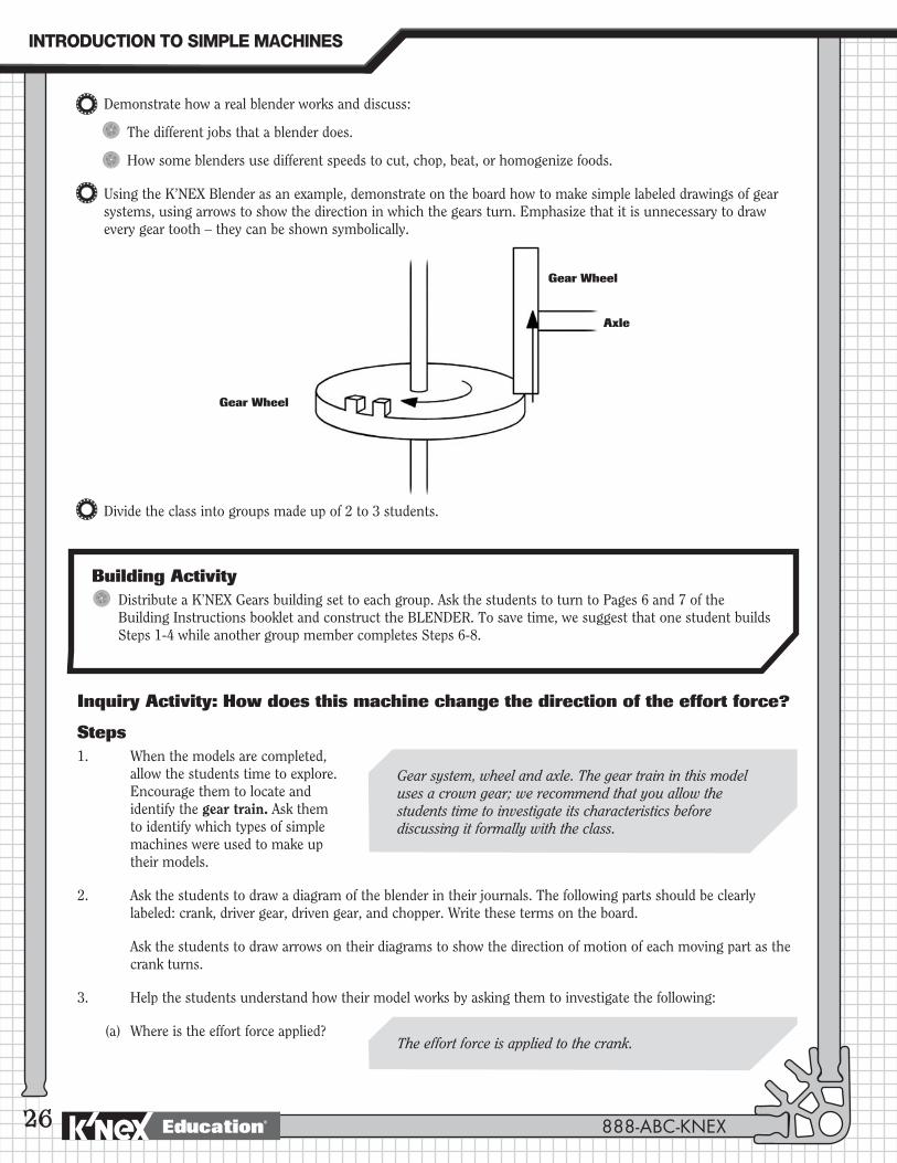
Using the K’NEX Blender as an example, demonstrate on the board how to make simple labeled drawings of gear systems, using arrows to show the direction in which the gears turn. Emphasize that it is unnecessary to draw every gear tooth – they can be shown symbolically.
Divide the class into groups made up of 2 to 3 students.
Building ActivityDistribute a K’NEX Gears building set to each group. Ask the students to turn to Pages 6 and 7 of the Building Instructions booklet and construct the BLENDER. To save time, we suggest that one student builds Steps 1-4 while another group member completes Steps 6-8.
Inquiry Activity: How does this machine change the direction of the effort force?
Steps1. When the models are completed,
allow the students time to explore. Encourage them to locate and identify the gear train. Ask them to identify which types of simple machines were used to make up their models.
2. Ask the students to draw a diagram of the blender in their journals. The following parts should be clearly labeled: crank, driver gear, driven gear, and chopper. Write these terms on the board.
Ask the students to draw arrows on their diagrams to show the direction of motion of each moving part as the crank turns.
3. Help the students understand how their model works by asking them to investigate the following:
(a) Where is the effort force applied?
Gear system, wheel and axle. The gear train in this model uses a crown gear; we recommend that you allow the students time to investigate its characteristics before discussing it formally with the class.
The effort force is applied to the crank.
Gear Wheel
Gear Wheel
Axle
888-ABC-KNEX
INTRODUCTION�TO�SIMPLE�MACHINES
Education®
(b) What type of motion is the input motion (or effort force)?
(c) Where does the output motion take place? What type of motion is it?
(d) Compare input and output motions. How are these motions the same? How are these motions different?
(e) Observe and describe the motion of each moving part. Is the part rotating in a vertical plane or a horizontal plane?
(f) Try to identify where the motion changes from moving in a vertical (up and down) plane to moving in a horizontal (or flat) plane.
(g) Ask the students to investigate and discuss with their team members:
(i) How they can control the speed of the output movement.
(ii) Why the crank rotates at the same speed as the cutting blades.
(iii) Whether or not the mechanism will be easier to turn without the crank handle.
4. Ask the students whether this gear system increases speed or changes the direction of motion. They should record their observations in their journals.
27
The output motion happens at the chopping blades. The output motion is also a rotational motion.
The driver and the driven gear wheels have the same number of teeth and rotate at the same speed. The crank is directly connected to the driver while the cutting blades are directly connected to the driven gear.
If your students have studied the wheel and axle they will be familiar with the fact that it is easier to turn the wheel (crank handle) than it is to turn the axle.
Students should notice that the gear system changes the direction of motion.
Crank: vertical; 1st gear: vertical; 2nd gear: horizontal; blades: vertical.
They are the same in that they are both rotational motions. They are different in that they rotate in opposite directions. Also, the chopper blades rotate in a horizontal plane. The crank turns in an up and down [vertical] plane. If your students are not familiar with the concept of planes, you may accept their operational description of the relationship between the gears. Students may say one gear is flat and the other is on its edge.
The input motion is a rotational motion.
Adjust the speed at which they turn the crank.
BlenderGEARS
www.knexeducat ion.com Education®
28
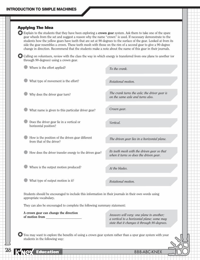
Applying The IdeaExplain to the students that they have been exploring a crown gear system. Ask them to take one of the spare gear wheels from the set and suggest a reason why the name “crown” is used. If necessary demonstrate to the students how the yellow gears have teeth that are set at 90-degrees to the surface of the gear. Looked at from its side the gear resembles a crown. These teeth mesh with those on the rim of a second gear to give a 90-degree change in direction. Recommend that the students make a note about the name of this gear in their journals.
Calling on volunteers, review with the class the way in which energy is transferred from one plane to another (or through 90-degrees) using a crown gear.
Where is the effort applied?
What type of movement is the effort?
Why does the driver gear turn?
What name is given to this particular driver gear?
Does the driver gear lie in a vertical or horizontal position?
How is the position of the driven gear different from that of the driver?
How does the driver transfer energy to the driven gear?
Where is the output motion produced?
What type of output motion is it?
Students should be encouraged to include this information in their journals in their own words using appropriate vocabulary.
They can also be encouraged to complete the following summary statement:
A crown gear can change the direction of motion from _______________________
You may want to explore the benefits of using a crown gear system rather than a spur gear system with your students in the following way:
To the crank.
Rotational motion.
Crown gear.
Vertical.
The crank turns the axle; the driver gear is on the same axle and turns also.
Its teeth mesh with the driven gear so that when it turns so does the driven gear.
Answers will vary: one plane to another; a vertical to a horizontal plane; some may state that it changes it through 90-degrees.
The driven gear lies in a horizontal plane.
At the blades.
Rotational motion.
888-ABC-KNEX
INTRODUCTION�TO�SIMPLE�MACHINES
Education®
29
Blender
1. Review their findings - a crown gear system helps do work by changing the direction of motion. This means that the effort force can be applied in the direction that is easiest and have the work take place in a different direction.
2. Ask them to compare the space taken up with a crown gear system and a spur gear system. The students should recognize that a crown gear system could produce a more compact arrangement.
Ask the students to record these benefits in their journals using appropriate vocabulary.
Extending The IdeaAsk students whether or not they think that the same principles of gear ratios, speed, and force that they observed in spur gear systems also applies to crown gear systems. Have the students write their predictions in their journals.
Direct the students’ attention to the building instructions for the EGGBEATER on Pages 10 and 11 of the Building Instruction booklet. Discuss some of the features of an eggbeater’s design – the need for a fast output speed from the beaters to mix the eggs faster and more efficiently than by using a fork, for example.
What other machine have they studied that must operate at high speed?
Could a similar gear system and mechanism be used to operate an eggbeater?
1. Ask the students if they can interpret how this machine works using only the building instruction diagrams on Pages 10 and 11.
Use questioning strategies to determine student understanding:
(a) Look at the diagrams and identify the parts that move and suggest what their function might be.
(b) Suggest how the moving parts are joined together to create a change in direction.
(c) Describe the direction of the input force and the direction of the output force.
(d) Identify the driver and driven gears.
(e) What is the direction of rotation of the driver and driven gears?
(f) Describe how the eggbeater gears are arranged differently from the crank fan gears.
(g) Will the handle rotate at the same speed as the beaters?
(h) Do the beaters turn in the same direction?
(i) Will the mechanism be easy or difficult to turn if the handle is removed?
2. The students should be given time to record their ideas in their journals.
3. Allow students time to build and investigate the K’NEX EGGBEATER.
4. (a) Ask the students to explain the movements and function of the mechanism they have investigated.
(b) How did their interpretation of the drawings differ from what they found when they built the model?
(c) Ask the students to describe whether it was easier to investigate the drawing or the model. They should be prepared to explain their answer.
Crank fan.
GEARS
www.knexeducat ion.com Education®
30
JOURNAL CHECK: 4 Identification of the gear mechanism.
4 Diagram of the blender, including labels and arrows.
4 Record of student observations as indicated by responses to questions in Step 3.
4 Identification of the relative motions of moving parts.
4 Identification of the change in direction of motion and force.
4 How did the crown gear get its name?
4 Benefits of using a crown gear system to change the direction of motion.
NOTES:
__________________________________________________________________________________________________
__________________________________________________________________________________________________
__________________________________________________________________________________________________
__________________________________________________________________________________________________
__________________________________________________________________________________________________
__________________________________________________________________________________________________
__________________________________________________________________________________________________
__________________________________________________________________________________________________
__________________________________________________________________________________________________
__________________________________________________________________________________________________
__________________________________________________________________________________________________
__________________________________________________________________________________________________
__________________________________________________________________________________________________
__________________________________________________________________________________________________
__________________________________________________________________________________________________
__________________________________________________________________________________________________
__________________________________________________________________________________________________
__________________________________________________________________________________________________
888-ABC-KNEX
INTRODUCTION�TO�SIMPLE�MACHINES
Education®
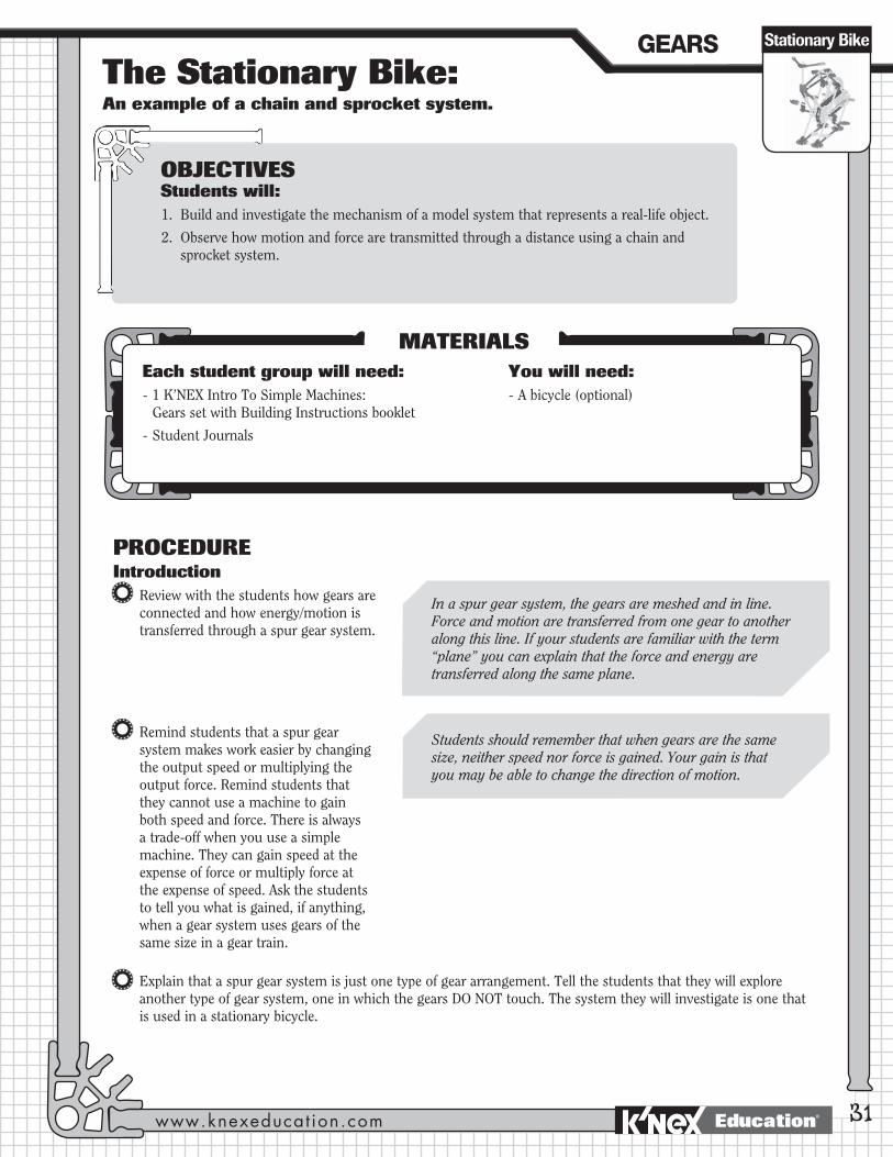
The Stationary Bike: An example of a chain and sprocket system.
31
PROCEDUREIntroduction
Review with the students how gears are connected and how energy/motion is transferred through a spur gear system.
Remind students that a spur gear system makes work easier by changing the output speed or multiplying the output force. Remind students that they cannot use a machine to gain both speed and force. There is always a trade-off when you use a simple machine. They can gain speed at the expense of force or multiply force at the expense of speed. Ask the students to tell you what is gained, if anything, when a gear system uses gears of the same size in a gear train.
Explain that a spur gear system is just one type of gear arrangement. Tell the students that they will explore another type of gear system, one in which the gears DO NOT touch. The system they will investigate is one that is used in a stationary bicycle.
OBJECTIVESStudents will:1. Build and investigate the mechanism of a model system that represents a real-life object.
2. Observe how motion and force are transmitted through a distance using a chain and sprocket system.
MATERIALSEach student group will need: - 1 K’NEX Intro To Simple Machines:
Gears set with Building Instructions booklet
- Student Journals
You will need: - A bicycle (optional)
Students should remember that when gears are the same size, neither speed nor force is gained. Your gain is that you may be able to change the direction of motion.
In a spur gear system, the gears are meshed and in line. Force and motion are transferred from one gear to another along this line. If your students are familiar with the term “plane” you can explain that the force and energy are transferred along the same plane.
GEARS
www.knexeducat ion.com
Stationary Bike
Education®
32
Discuss how the stationary bicycle’s design is based on a 2-wheel bicycle. If possible provide an example of a bicycle for the students to investigate. Alternatively, ask the students to look at Pages 12 and 13 of the Building Instructions booklet to interpret how they think the mechanism works.
Ask them questions about how the bicycle works and encourage them to use terms they already know that are associated with a bicycle’s gear system:
Where does the power come from to drive the bicycle?
Which parts move and what are their functions?
How is the power transferred to the rear wheel?
How is the gear arrangement in this mechanism different from the spur gear system they have studied?
Responses to this question will give you the opportunity to discuss the chain and sprocket drive system.
Divide the class into groups made up of 2 to 3 students.
Building ActivityDistribute a K’NEX Gears set to each group.
Ask the students to turn to Pages 12 and 13 of the Building Instructions booklet and construct the model of the STATIONARY BIKE. To save time, we suggest that one student completes Steps 1-6 at the same time as another group member completes Steps 7-11.
Inquiry Activity: How is motion and force transferred using a chain and sprocket system?
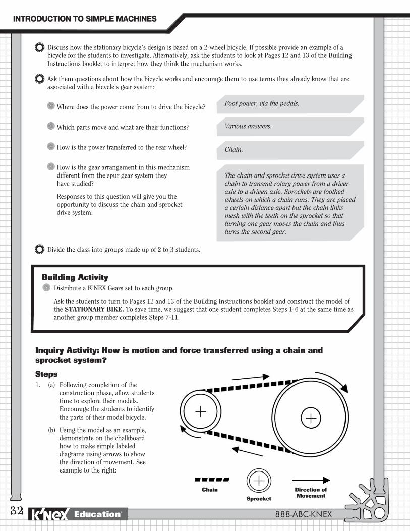
Steps1. (a) Following completion of the
construction phase, allow students time to explore their models. Encourage the students to identify the parts of their model bicycle.
(b) Using the model as an example, demonstrate on the chalkboard how to make simple labeled diagrams using arrows to show the direction of movement. See example to the right:
Foot power, via the pedals.
Various answers.
Chain.
The chain and sprocket drive system uses a chain to transmit rotary power from a driver axle to a driven axle. Sprockets are toothed wheels on which a chain runs. They are placed a certain distance apart but the chain links mesh with the teeth on the sprocket so that turning one gear moves the chain and thus turns the second gear.
Chain Direction of MovementSprocket
888-ABC-KNEX
INTRODUCTION�TO�SIMPLE�MACHINES
Education®
(c) Ask the students to sketch a diagram of their bicycles. Encourage them to give names to the various parts of their model. You can then decide whether or not to formalize these. The following terms may be helpful:
Sprocket, chain, pedal, drive mechanism, links, driver gear, driven gear, driver axle, driven axle.
(d) Have the students draw arrows on their diagrams to show the direction each part moves as the pedals are turned.
(e) Ask the students to compare the direction of motion of the axle on the driver gear with the direction of motion of the axle on the driven gear.
(f) Students should record all their observations.
2. Encourage the students to continue exploring the chain and sprocket mechanism as they answer the questions below. Ask the students to record their responses.
(a) Where is the effort force applied? What type of motion is the input motion?
(b) Where does the output motion take place? What type of motion is it?
(c) What is the function of the chain in this system?
(d) Describe the transfer of energy/motion through your stationary bike system. Start at the pedals and end at the rear wheel.
Applying The IdeaNOTE: It may be helpful to have a model of the crank fan available for comparison at this point in the lesson.
Ask the students to write one reason why bicycles use a chain and sprocket system rather than a spur gear system. Remind them to use their crank fan notes if they need a little refresher on spur gears.
33
The effort force is applied to the pedals. The input motion is a rotational or circular motion.
The output motion happens at the back wheel. The output motion is also a rotational or circular motion.
The chain transfers energy/motion from the gear at the pedals to the gear at the rear wheel.
Answers will vary. Possible answer: In a spur gear system, the driven gear turns in the opposite direction to the driver gear. To go forward, you would have to pedal backwards.
Turning the pedals transfers motion and its energy along the driver axle to the sprocket at the front of the bike (driver gear). As the front sprocket turns, motion is transferred to the chain. The chain transfers that motion and its energy to the rear sprocket (driven gear). The turning of the driven gear turns the rear wheel.
Both axles turn in the same direction.
Stationary BikeGEARS
www.knexeducat ion.com Education®
34
JOURNAL CHECK:
The following should be recorded:
4 Identification of the gear mechanism.
4 Diagram of the stationary bicycle, including labels and arrows.
4 Record of student observations as indicated by responses to questions in Step 2.
4 Identification of relative motions of moving components.
4 Description of the transfer of energy/motion through the bicycle system.
When the students are finished, ask individual students to share their ideas with the class. Record student responses on the board.
Review the list. Ask the students to think about other machines that transfer motion over a distance. Tell the students that chains are not the only way to transfer motion over a distance. Encourage them to brainstorm a list of other machines that use a sprocket system to transfer motion. They will need help with this and it may be a good idea to have pictures of some of the machines listed below. You can then ask the students to work out where the chain and sprocket system is found in them. Examples you could use:
The checkout counter at the grocery store - a checkout uses a conveyor system.
A roller coaster at an amusement park - a chain is used to pull the roller coaster up the first big hill.
An escalator in a department store.
Extending The Idea[Grade: 5]
1. Remind students that the term gear ratio refers to the number times the driven gear turns relative to the number of times the driver gear turns. Ask the students to estimate the gear ratio of their stationary bike models.
[Grade: 5]
2. Ask students to explain why ten-speed and mountain bikes use several different sized gears.
Students should be able to conclude that the gear ratio is 1:1 based on the identical nature of the gears used.
Possible answers: Different combinations of gears provide different gear ratios. Most will probably suggest that they use different sized gears going up hills compared to riding on flat streets.
888-ABC-KNEX
INTRODUCTION�TO�SIMPLE�MACHINES
Education®
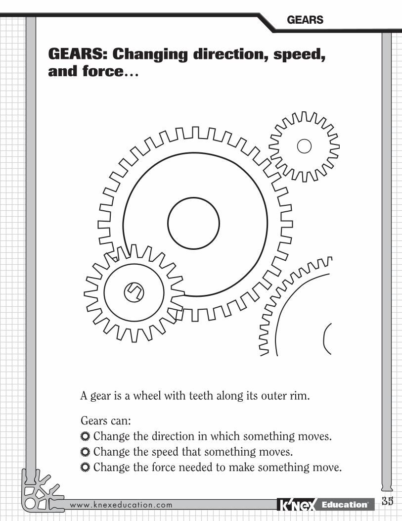
GEARS: Changing direction, speed, and force…
A gear is a wheel with teeth along its outer rim.
Gears can: Change the direction in which something moves. Change the speed that something moves. Change the force needed to make something move.
GEARS
www.knexeducat ion.com 35Education®
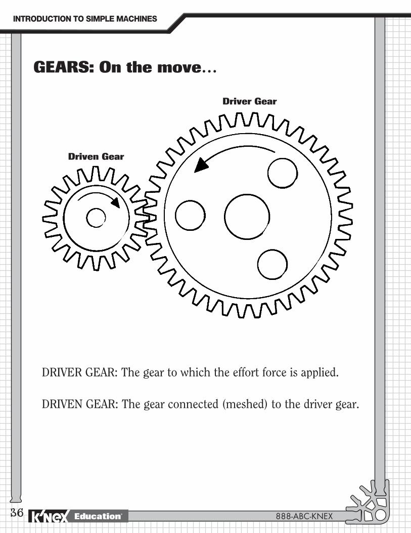
GEARS: On the move…
Driver Gear
Driven Gear
DRIVER GEAR: The gear to which the effort force is applied.
DRIVEN GEAR: The gear connected (meshed) to the driver gear.
36 888-ABC-KNEX
INTRODUCTION�TO�SIMPLE�MACHINES
Education®
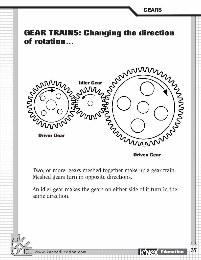
GEAR TRAINS: Changing the direction of rotation…
Two, or more, gears meshed together make up a gear train. Meshed gears turn in opposite directions.
An idler gear makes the gears on either side of it turn in the same direction.
Driver Gear
Driven Gear
Idler Gear
GEARS
www.knexeducat ion.com 37Education®
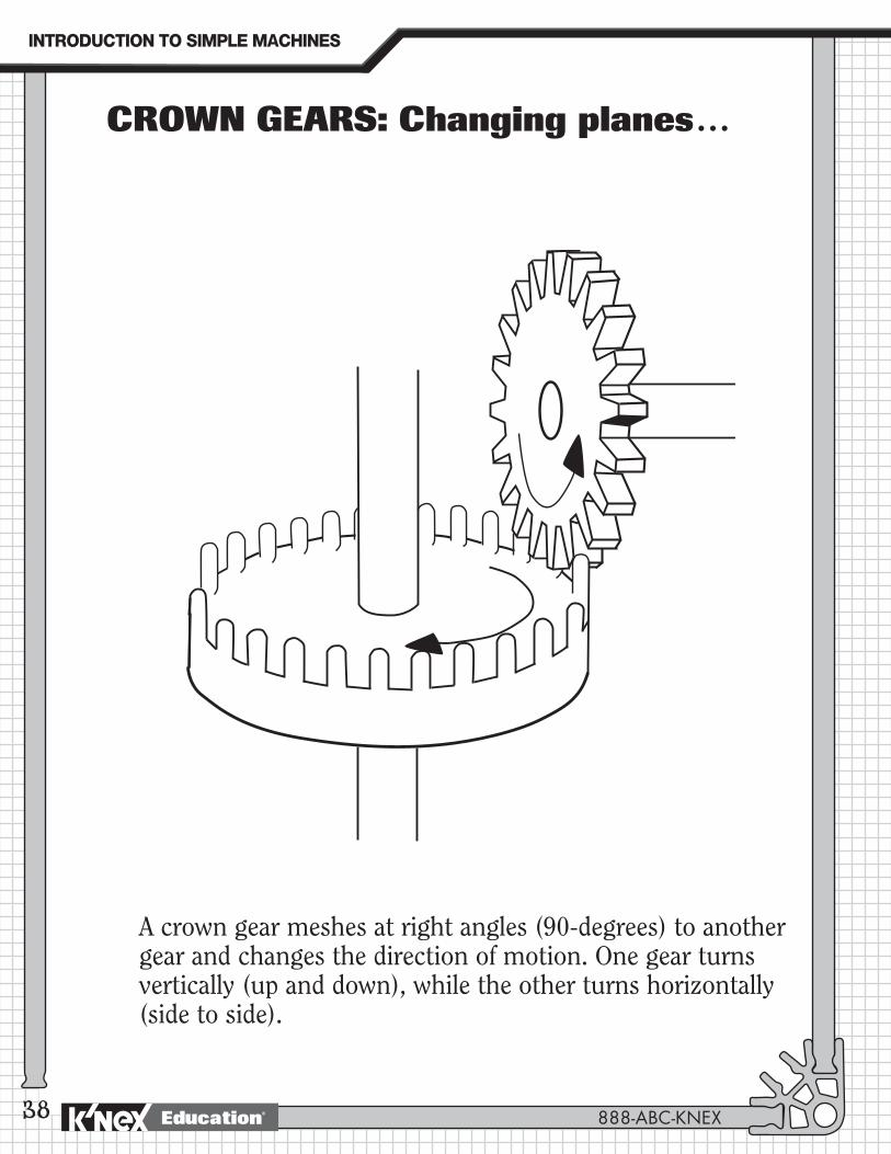
CROWN GEARS: Changing planes…
A crown gear meshes at right angles (90-degrees) to another gear and changes the direction of motion. One gear turns vertically (up and down), while the other turns horizontally (side to side).
38 888-ABC-KNEX
INTRODUCTION�TO�SIMPLE�MACHINES
Education®
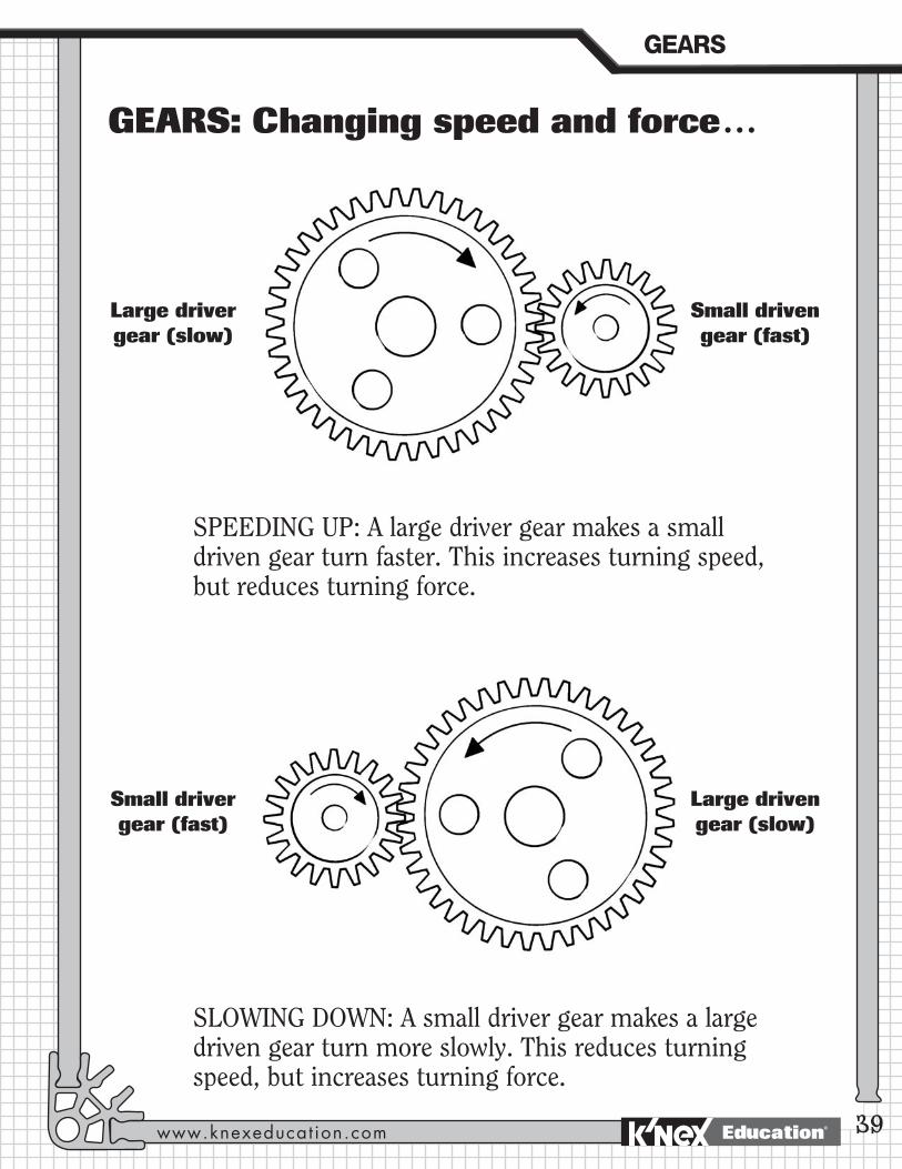
GEARS: Changing speed and force…
SPEEDING UP: A large driver gear makes a small driven gear turn faster. This increases turning speed, but reduces turning force.
SLOWING DOWN: A small driver gear makes a large driven gear turn more slowly. This reduces turning speed, but increases turning force.
Large driver gear (slow)
Small driven gear (fast)
Large driven gear (slow)
Small driver gear (fast)
GEARS
www.knexeducat ion.com 39Education®
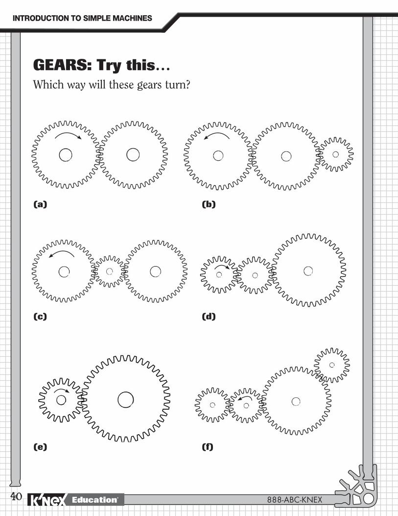
GEARS: Try this…Which way will these gears turn?
(a) (b)
(c) (d)
(e) (f)
40 888-ABC-KNEX
INTRODUCTION�TO�SIMPLE�MACHINES
Education®