Embed Size (px)
Citation preview
BRL 02480 c. 3A
\\ '. CIRCULATING COPY
EE HOV jwe: '.^ mtflH'(r<CTl
TECHNICAL REPORT ARBRL-TR-02480
GED: AN INTERACTIVE SOLID MODELING
SYSTEM FOR VULNERABILITY ASSESSMENTS
Michael J. Muuss Keith A. Applin
J. Robert Suckling Gary S. Moss
Earl P. Weaver Charles A. Stanley
m
TECHNICAL REPORTS SECTION STIHFO BRANCH _^^^^ ELDG. 3Q5 ~~
March 1983
US ARMY ARMAMENT RESEARCH AND DEVELOPMENT COMMAND BALLISTIC RESEARCH LABORATORY ABERDEEN PROVING GROUND, MARYLAND
Approved for public release; distribution unlimited.
Destroy this report when it is no longer needed. Do not return it to the originator.
Additional copies of this report may be obtained from the National Technical Information Service, Ü. S. Department of Commerce, Springfield, Virginia 22161.
The findings in this report are not to be construed as an official Department of the Army position, unless so designated by other authorized documents.
The uae of trade nones or manufacturers' names in this report does not constitute indorsement of any aormeroial produot.
UNCLASSIFIED SECURITY CLASSIFICATION OF THIS PAGE {When Data Entered)
REPORT DOCUMENTATION PAGE READ INSTRUCTIONS BEFORE COMPLETING FORM
1. REPORT NUMBER
TECHNICAL REPORT ARBRL-TR-02480
2. GOVT ACCESSION NO 3.. RECIPIENT'S CATALOG NUMBER
4. TITLE (and Subtitle)
GED: AN INTERACTIVE SOLID MODELING SYSTEM FOR VULNERABILITY ASSESSMENTS
S. TYPE OF REPORT 4 PERIOD COVERED
Final 6. PERFORMING ORG. REPORT NUMBER
7. AUTHORf«)
Michael J. Muuss Keith A. Applin J. Robert Suck!ing
B. CONTRACT OR GRANT NUMBERfsJ
Gary S. Moss Earl P. Weaver Charles A. Stanley
9. PERFORMING ORGANIZATION NAME AND ADDRESS
U.S. Army Ballistic Research Laboratory ATTN: DRDAR-BLV Aberdeen Proving Ground, MD 21005
10. PROGRAM ELEMENT, PROJECT, TASK AREA a WORK UNIT NUMBERS
1L162618AH80 It. CONTROLLING OFFICE NAME AND ADDRESS 12. REPORT DATE
March 1983 U.S. Army Armament Research & Development Command U.S. Army Ballistic Research Laboratory (DRDAR-Bl )a NUMBER OF PAGES Aberdeen Proving Ground, MD 21005 46
14. MONITORING AGENCY NAME ft ADDRESS^/ dlllerent from Controlling Office) IS. SECURITY CLASS, (ot thta report)
Unclassified »5«. DECLASSIFICATION/DOWNGRAOING
SCHEDULE
16- DISTRIBUTION STATEMENT (of thie Report)
Approved for public release; distribution unlimited.
17. DISTRIBUTION STATEMENT (ot the aba tract entered In Block 20. It dl Heren t from Report)
TECHNICAL REPORT* SECTION STRFO BRAUCH ~ ; BLDG. 308 3" 18. SUPPLEMENTARY NOTES
19. KEY WORDS (Continue on teverae aide It nee e a eery and Identity by block number)
Target Descriptions Interactive Computer Graphics Combinatorial Geometry
20s ABSTRACT (Continue an revere» «{«to H rmcooafr and. Identify by block number)
For many years the production and modification of target descriptions, no matter what method used, has been a slow, labor-intensive procedure. In an effort to improve the response time of target descriptions, the Ballistic Research Laboratory (BRL) has developed an interactive solid modeling system. This system is called the Graphics Editor (GED) and is designed to replace the traditional manual method of production and modification of target descriptions GED presently applies to the combinatorial geometry (COMGEOM) solid modeling
(cont'd) DD FOR»
1 JAM 73 1473 EDITION OF » MOV eS IS OBSOLETE UNCLASSIFIED SECURITY CLASSIFICATfON OF THIS PAGE (When Data Entered)
UNCLASSIFIED SECURITY CLASSIFICATION OP THIS PAOE(T*7i«n Data Bnter**)
technique. Using GED, the target descriptions are Interactively viewed, modified, and constructed with Immediate visual feedback at each step. The GED system virtually eliminates explicit numerical Input and opens a new dimension 1n the target description process.
•>.
UNCLASSIFIED
SECURITY CLASSIFICATION OF THIS FA.<Z£(Whpn Data Entered)
TABLE OF CONTENTS Page
LIST OF ILLUSTRATIONS 5
I. INTRODUCTION 7
II. COMGEOM BACKGROUND 7
III. COMPUTER GRAPHICS 9
IV. APPROACH TO THE PROBLEM 9
V. GED OVERVIEW. 11
VI. GED INTERNAL DATA STRUCTURE 11
VII. KEYBOARD COMMANDS 12
VIII. PERIPHERAL DEVICES. 22
IX. ANGLE DISTANCE CURSOR (ADC) 22
X. VIEWING FUNCTIONS 26
XI. SELECTING OBJECTS FOR EDITING .27
XII. OBJECT EDITING 28
XIII. SOLID EDITING 29
A. ARB Parameter Editing . ... 32
B. TGC Parameter Editing 34
C. ELLG Parameter Editing 36
D. TOR Parameter Editing 36
XIV. CONCLUSION 38
DISTRIBUTION LIST 41
TECHNICAL REPORTS &ECT1CH ST1NF0 BRANCH
BLOG. 3U5

This page Left Intentionally Blank
LIST OF ILLUSTRATIONS
Figure Page
1. Logic Operations Used to Combine Solids 10
2. Sample Hierarchy of Object "heround" .... 13
3. Tasks Assigned to the Function Switch Buttons 23
4. Functions Assigned to the Control Knobs 24
5. The Angle Distance Cursor. 25
6. Typical Generalized ARBs 33
7. Typical TGCs 35
8. Typical ELLGs 37
9. TOR Parameters 39

This page Left Intentionally Blank
I. INTRODUCTION
As the Army's lead laboratory for vulnerability technology, the Ballistic Research Laboratory (BRL) constantly performs vulnerability analyses for a wide variety of military systems. Vital to these vulnerability studies are three -dimensional computer models of the physical characteristics of these systems. These computer models are generally called target descriptions. Since the mid 1960's, BRL has used a solid modeling technique called combinatorial geometry (COMGEOM) to model targets. The COMGEOM technique uses logic operations to combine basic geometric shapes or primitives to produce the three-dimensional target description. The COMGEOM target descriptions are processed by the Geometric Information For Targets (GIFT) * code for use in follow- on vulnerability assessment codes.
Target descriptions are basically large collections of numerical data which traditionally have been handled manually in a batch environment* Hence, the production and modification of target descriptions has been a slow, labor-intensive process. In 1980, BRL initiated an effort to improve the response time of the target description process by applying interactive computer graphics techniques. As a result of this work unit, BRL has developed the Graphics EDitor (GED), an interactive solid modeling system based on the COMGEOM technique. Using GED an analyst can view, build, and modify target descriptions interactively by manipulating the graphical representation, thus providing immediate visual feedback on a vector display device. The GED system is designed to replace the manual method of production and modification of target descriptions.
This report is Intended to serve as a user manual for the GED system. The process of viewing and editing a description using GED is covered in detail. The internal data structure is also covered, as it is an important part in the overall design of the GED system.
II. COMGEOM BACKGROUND
Since the GED system is presently based on the COMGEOM solid modeling technique, a brief overview of the COMGEOM technique is required to effectively use GED. For more detailed information on the COMGEOM technique see References 1 and 2.
The COMGEOM technique utilizes two basic entities - a solid and a region. A solid Is defined as one of fifteen basic geometric shapes or primitives. Table I contains a list of these fifteen solids. The individual parameters of each solid define the solid's location, size,
Lawrence W. Bain, Mathew J. Reisinger, "The GIFT Code User Manual; Vol I, Introduction and Input Requirements," BRL Report No. 1802, July 1975 (AD0 B0060371)
2 Gary G. Kuehl, Lawrence W. Bain, Mathew J. Reisinger, "The GIFT Code
User Manual; Vol II, the Output Options," ARRADCOM Technical Report No. ARBRL-TR-02189, September 1979 (AD# A07836A)
Table I. COMGEOM SOLIDS
Symbol
ARS
ARB
RPP
BOX
RAW
ELLG
ELL
SPH
TGC
RCC
REC
TRC
TEC
TOR
HAF
Name
Triangular Surfaced Polyhedron
Arbitrary Convex Polyhedron
Rectangular Parallelepiped
Box
Right Angle Wedge
General Ellipsoid
Ellipsoid of Revolution
Sphere
Truncated General Cone
Right Circular Cylinder
Right Elliptical Cylinder
Truncated Right Cylinder
Truncated Elliptical Cylinder
Torus
Half Space
and orientation« A region Is a combination of one or more solids and Is defined as the volume occupied by the resulting combination of solids» Solids are combined Into regions using any of three logic operations: unlon(OR), lntersectlon(+), or dlfference(-). The union of two solids 16 defined as the volume In either of the solids* The difference of two solids Is defined as the volume of the first solid minus the volume of the second solid. The Intersection of two solids 16 defined as the volume common to both solids. Figure 1 presents a graphical representation of these operations. Any number of solids may be combined to produce a region. As far as the COMGEOM technique is concerned, only a region can represent a component of the target. The solids are only building blocks to be combined Into regions» Since regions represent the components of the target system, they are further Identified by code numbers. These code numbers either Identify the region as a target component (nonzero Item code) or as air (nonzero air code). Any volume not defined as a region Is assumed to be "universal air" and Is given an . air code of "01." if It Is necessary to distinguish between universal "01" air and any other kind of air, then that volume must be defined as a region and given an air code other than "01." Normally, regions cannot occupy the same volume (overlap), but regions Identified with air codes can overlap with any region identified as a component (I.e., one that has a nonzero item code). Regions Identified with different air codes,however, can not overlap«
III. COMPUTER GRAPHICS
Computer graphics is one of the fastest growing fields in the computer industry. Computer graphics has applications in many diverse areas, from electronic games to medicine, from cartoons to the space industry. Just what is interactive computer graphics and why is it so versatile? Human visual perception is quite keen and communications with a computer are generally faster and easier with images or displays rather than with numbers. Furthermore, by driving the display image with the computer, one can actually communicate with the computer through the display itself. This technology is called Interactive computer graphics. The user converses with the computer through the display using devices such as light pens, data tablets, function switches, and control dials« The response of the computer is Immediately reflected on the display. Thus,a fast channel of communication is available between person and machine.
IV. APPROACH TO THE PROBLEM
To speed up the model description process, a faster, more efficient method of manipulating the large masses of data Involved in a target description Is needed. Interactive computer graphics seems to provide the capability of handling such data in an efficient, relatively fast manner. The key to the whole situation Is SOFTWARE - the missing link between the target description problem and a possible solution«
In view of this fact, existing software graphics packages were evaluated with respect to their utility in the target description
Figure 1. Logic Operations Used to Combine Solids
10
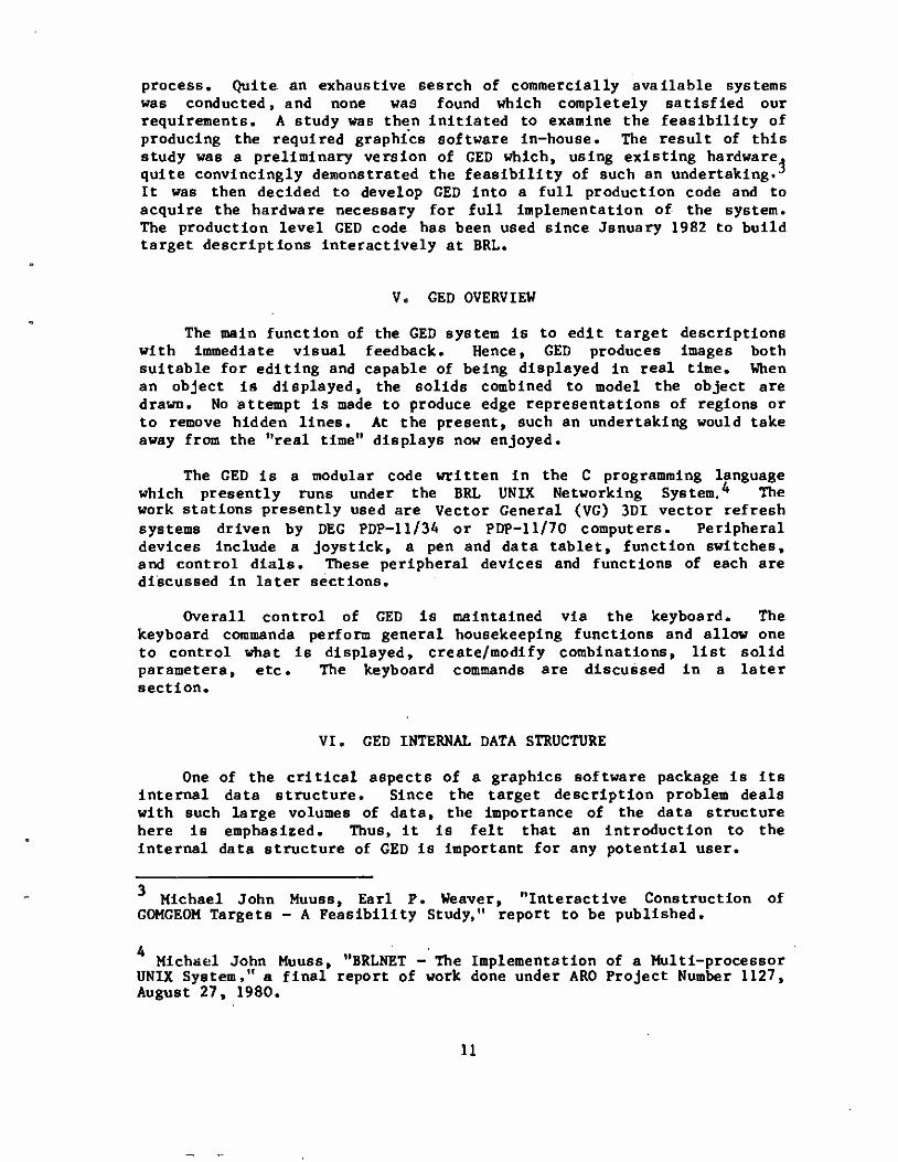
process. Quite, an exhaustive search of commercially available systems was conducted, and none was found which completely satisfied our requirements. A study was then initiated to examine the feasibility of producing the required graphics software in-house. The result of this study was a preliminary version of GED which, using existing hardware, quite convincingly demonstrated the feasibility of such an undertaking.3
It was then decided to develop GED into a full production code and to acquire the hardware necessary for full implementation of the system. The production level GED code has been used since January 1982 to build target descriptions interactively at BRL.
V. GED OVERVIEW
The main function of the GED system is to edit target descriptions with immediate visual feedback. Hence, GED produces images both suitable for editing and capable of being displayed in real time. When an object is displayed, the solids combined to model the object are drawn. No attempt is made to produce edge representations of regions or to remove hidden lines. At the present, such an undertaking would take away from the "real time" displays now enjoyed.
The GED i6 a modular code written in the C programming language which presently runs under the BRL UNIX Networking System. ^ The work stations presently used are Vector General (VG) 3DI vector refresh systems driven by DEC PDP-11/34 or PDP-ll/70 computers. Peripheral devices include a joystick, a pen and data tablet, function switches, and control dials. These peripheral devices and functions of each are discussed in later sections.
Overall control of GED is maintained via the keyboard. The keyboard commands perform general housekeeping functions and allow one to control what is displayed, create/modify combinations, list solid parameters, etc. The keyboard commands are discussed in a later section.
VI. GED INTERNAL DATA STRUCTURE
One of the critical aspects of a graphics software package is its internal data structure. Since the target description problem deals with such large volumes of data, the importance of the data structure here is emphasized. Thus, it is felt that an introduction to the internal data structure of GED is important for any potential user.
3 Michael John Muuss, Earl P. Weaver, "Interactive Construction of
COMGEOM Targets - A Feasibility Study," report to be published.
4 Michael John Muuss, "BRLNET - The Implementation of a Multi-processor UNIX System,1' a final report of work done under ARO Project Number 1127, August 27, 1980.
11
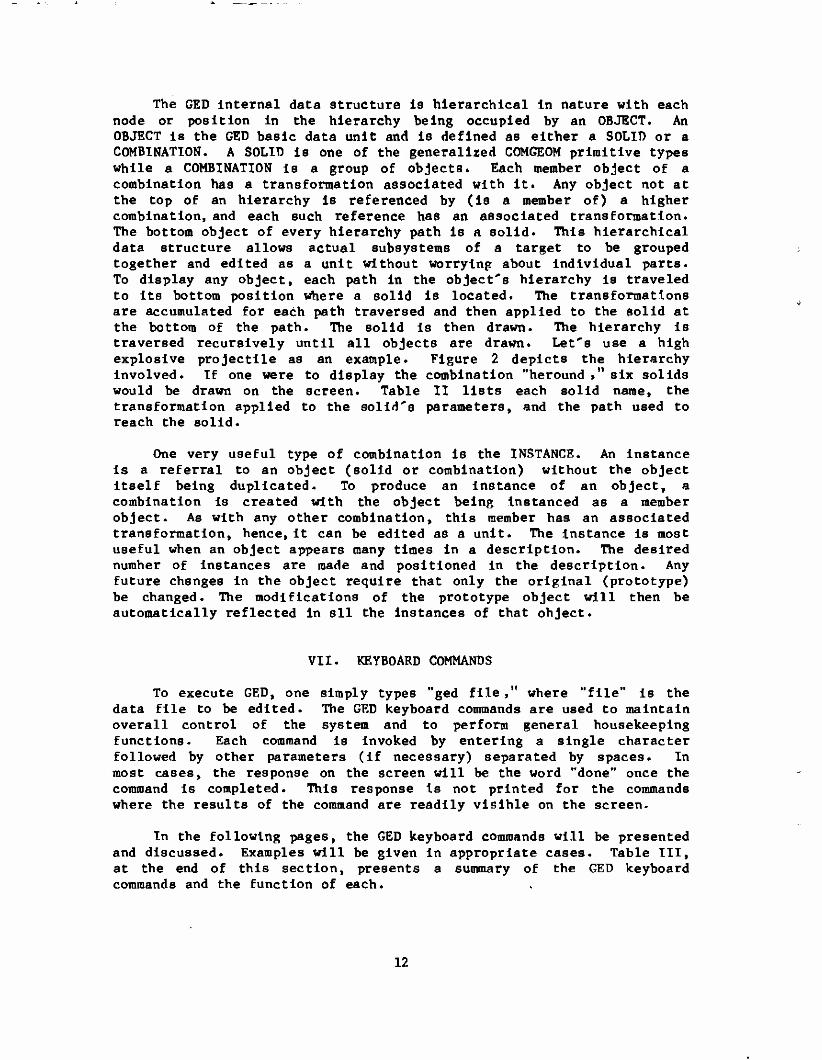
The GED internal data structure is hierarchical in nature with each node or position in the hierarchy being occupied by an OBJECT. An OBJECT is the GED basic data unit and is defined as either a SOLID or a COMBINATION. A SOLID is one of the generalized COMGEOM primitive types while a COMBINATION is a group of objects. Each member object of a combination has a transformation associated with it. Any object not at the top of an hierarchy Is referenced by (is a member of) a higher combination, and each such reference has an associated transformation. The bottom object of every hierarchy path is a solid. This hierarchical data structure allows actual subsystems of a target to be grouped together and edited as a unit without worrying about individual parts. To display any object, each path in the object's hierarchy Is traveled to its bottom position where a solid is located. The transformations are accumulated for each path traversed and then applied to the solid at the bottom of the path. The solid 1B then drawn. The hierarchy is traversed recursively until all objects are drawn. Let's use a high explosive projectile as an example. Figure 2 depicts the hierarchy involved. If one were to display the combination "heround »" six solids would be drawn on the screen. Table II lists each solid name, the transformation applied to the solid's parameters, and the path used to reach the solid.
One very useful type of combination is the INSTANCE. An instance Is a referral to an object (solid or combination) without the object itself being duplicated. To produce an instance of an object, a combination is created with the object being instanced as a member object. As with any other combination, this member has an associated transformation, hence, it can be edited as a unit. The instance Is most useful when an object appears many times in a description. The desired number of instances are made and positioned in the description. Any future chsnges in the object require that only the original (prototype) be changed. The modifications of the prototype object will then be automatically reflected in sll the instances of that object.
VII. KEYBOARD COMMANDS
To execute GED, one simply types "ged file," where "file" is the data file to be edited. The GED keyboard commands are used to maintain overall control of the system and to perform general housekeeping functions. Each command is invoked by entering a single character followed by other parameters (if necessary) separated by spaces. In most cases, the response on the screen will be the word "done" once the command is completed. This response is not printed for the commands where the results of the command are readily visible on the screen.
In the following pages, the GED keyboard commands will be presented and discussed. Examples will be given in appropriate cases. Table III, at the end of this section, presents a summary of the GED keyboard commands and the function of each.
12
hero und
7 ü\ "V shelkose propel lernt warhead he
+ X + + \5 r5
+
shel cases propellant.s profocasas he.s
Figure 2. Sample Hierarchy of Object "heround
Table II. Displaying Solids of Object "heround'
SOLID TRANSFORMATION DsasB3=33sasa3aBiimssa333sas3:
shellcase.s T2 * Tl
he «8
PATH :833SSE33S3a3S3=333e=3=3X=3B3B1
heround/shellease/shellease.s
propellant.s T2 * Tl heround/shellease/propellant.s
propellant.s T3 * Tl heround/propellant/propellant.a
projocase.s T4 * Tl heround/varhead/projocase.a
he.s T4 * Tl heround/varhead/he.8
T5 * Tl heround/he/he.8
13
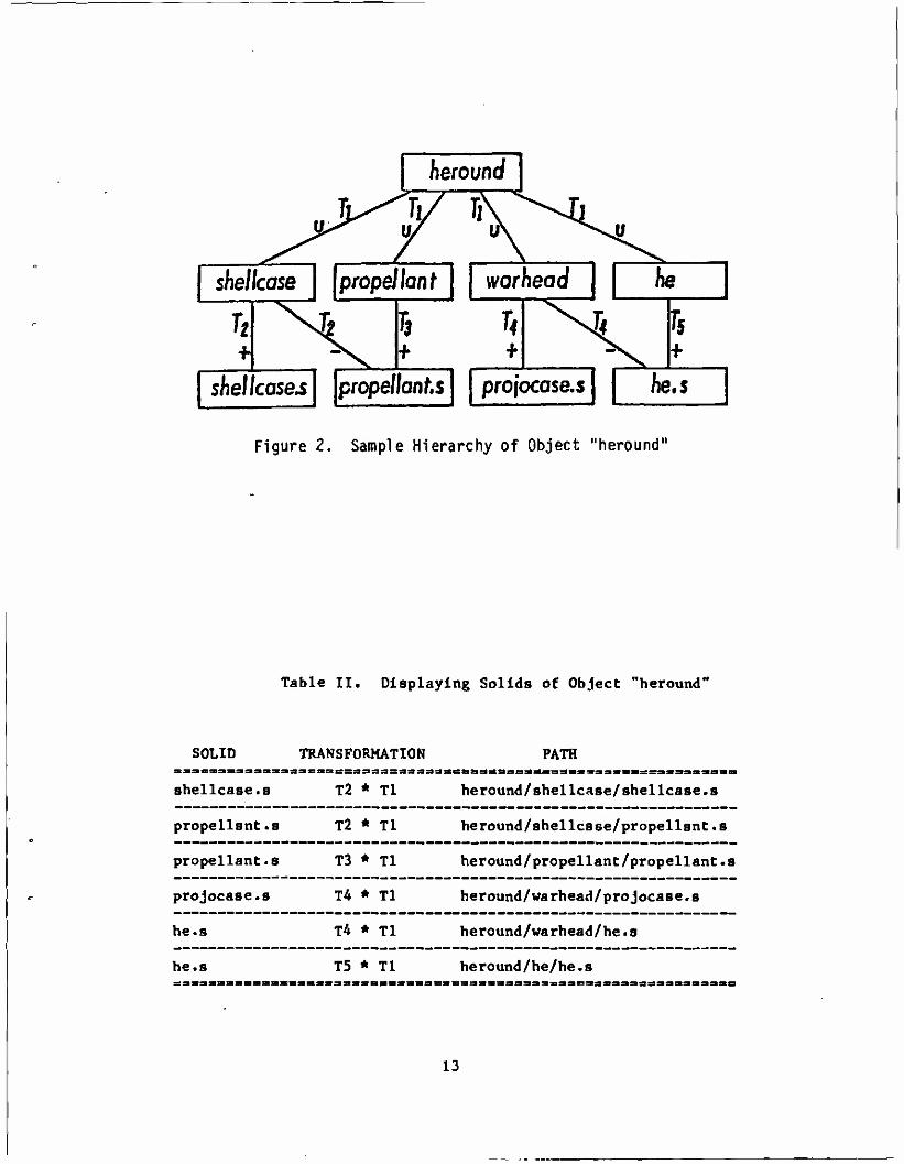
c oldsolid newsolid
This command is used to produce and display a copy of a solid. In this case» the solid "oldsolid" will be copied into a solid called "newsolid," A new identical solid record is added to the data file. The solid parameters are copied as they appear in the solid record.
Examples: c arb8 hullbot.s c arb8 turrettop.s c tgc wheelrim.s c tor tirel.s
n old new
This command is used to rename objects in the data file. In this case, the object "old" will be renamed "new." A note of caution: The name is changed only in the object record itself, not in any member records. Thus, if the object "old" appears as a member of any other object, the name will not be changed there.
Examples: n test hull n gOO air n gl turret
This command clears (Zaps) the screen of all displayed objects
14
g group objl ob j2 objn
This command creates or appends to a combination record and is used to group objects together either for editing or displaying purposes. Tn this case, "objl" through "objn" are added as members to the combination "group." If "group" does not exist, it is created and "objl" through "objn" are added as members.
Examples: g shell hull turret g tank wheels engine crew shell g tank track
r region opl soil op2 sol2 .... opn soln
This command is used to create regions or append to regions. If "region" exists, then solids "soil" through "soln" are added as members with "opl" through "opn" as the defining operations. Tf "region" does not exist, then it is created and solids "soil" through "soln" are added as members with "opl" through "opn" as the defining operations. A region is merely a combination record with a flag set and is distinguished from other combinations (groups) since it has meaning to the COMGEOM solid modeling system.
When a region is created, the item and air codes are set equal to zero. To change the item and air codes use the "I" command. Note: In the past all members of a region had to be solids, but recently regions have been allowed aB members of regions. Hence, the names "soli" can also be regions now.
Examples: r hulltop.r + hulltop.s - hullleft.s - hullright.s r gun + gun«a - gunin.s r gunair + gunin.s
15
i object combname brname
This command is used to make an instance of an object. An instance of an object is produced by creating a combination and making the object a member. In this case, an instance of "object" is made by creating the combination record "combname" (if "combname" does not already exist) and adding "object" as a member. This member also has a second name "brname" added to the member record, which can be thought of as the name of this branch in the hierarchical data structure. If "combname" already exists, then "object" is added as the next member and "brname" is added as the branch name.
An instance is used to refer to an object, without making actual copies of the object. Instances are useful when one is adding a certain component to a target description many times. Furthermore, any modifications to an object which has been instanced need only be done in the original (prototype) object. These modifications will then be automatically reflected in all the instances of the object.
Examples: i heround ammo hel i heround ammo he2 i heat ammo heatl i heat ammo heat2
f face distance
This command allows the user to project a face of an arb (arbitrary polyhedron) being edited a normal distance to create a new arb. The value of "face" Is 4 digits such as 1256. If the face Is projected in the wrong direction use a negative "distance." One use for this command is for producing armor plates of a desired thickness.
Examples: f 1234 20 f 2367 34.75 f 2367 -34.75
16
1 object
This command is used to list information about objects in the data file. The information listed depends on what type of record "object" is. If "object" is a combination record, then the members are listed. Tf "object" is a solid record, then the GED general solid type and the parameters as presently in the data file are listed. Note: Only the solid parameters as they exist in the solid record are listed; no transformation matrix is applied. Hence, if the solid was edited as a member of a combination, the "1" command will not reflect the editing in the listed parameters.
Examples: 1 hull 1 turret 1 turtop.s 1 arb8
m oldsolid newBolid axis
This command is used to create and display a new solid record which is the mirror image of an existing solid. The mirror image is about an axis and is created by changing the signs on the solid's parameters, depending on which axis the solid is mirrored about. In this case, a mirror image of the solid "oldsolid" will be created about the axis indicated by "axis," and the new solid record will be called "newsolid." The only acceptable values for the parameter "axis" are "x," "y," and "z."
Examples: m tur.left.s tur.right.s y m tur.top.s tur.bot.s z m tur«front.9 tur.back.a x
17
p dx [dyj [dz]
This command allows a user In the SOLID EDITING mode to Input exact parameter modifications by the keyboard. The meaning of the values typed after the p command varies,depending on what solid editing feature is being used. Examples of this command will be given in the discussion on solid editing.
D comb raeml mera2 .... memn
This command allows one to delete members from a combination record. In this case, members "meral" through "memn" will be deleted from the combination "comb."
Examples: D tank hull wheels D regionl solidß solidll2 D turtop.r tursidel.s turslder.s turback.s
I region item air
This command allows one to change the item or air code numbers of a region. If the air code ("air") is not included, a zero is assumed. To change the air code, a zero item code should be used. (See second example below.)
Examples: I regionl 105 I region7 0 2 I regionl1 129 0
18
e object
This command is used to display (draw) objects on the screen. In this case, "object" will be displayed on the screen. Note that "object" must be found in the table of contents.
d object
This command is used to drop (delete) objects from the display. In this case, "object" will be deleted from the screen display. This command is opposite of the "e" command.
k object
This command Is used to remove (kill) objects from the data file. In this case, "object" will be removed from the data file. Note the distinction between the "d" command which deletes objects from the display and the "k" command which removes objects from the data file.
This command produces a list of the table of contents of all objects in the data file. The objects are listed a screenfull at a time. A carriage return will produce the next screenfull.
19
a arbnarae rot fb
This command is used to create and display a new arb8 solid record. This new arb8 has two square (5 units x 5 units) parallel faces which are 0.5 units apart. These parallel faces are in planes whose orientations are defined by the two Input angles - the rotation (rot) angle and the fallback (fb) angle. The orientation of armor plates are frequently defined using rotation and fallback angles. The vertex of this new arb8 is located In the center of the screen.
Examples: a hullsec3.s 45 30 a tursec2.s 90 20 a topglacls.s 0 60
This command is the display debug command. Tt will produce a list of all objects that have been displayed, the paths traversed to draw the objects, and whether or not the objects are displayed in the present view.
This command is used to quit the graphics editor code. This is the normal halt.
20

Table TIT. Summary of GED Keyboard Commands
TASK : aa5SBBBBB3»BaBS3SJSBB33B3=33»BSBs=öBB•
create/modify a region :
: COMMAND • =aB333=s;aiiaa3SBa333daaaaaseaaaaaa3aa33=
: r region opl soil .... opn soln
create Instance of object : : 1 object comblnatlonname lnstancename
make copy of a solid : : c oldname newname
rename object : : n oldname newname
group objects
display (view) object : : e object
list object Information : : 1 object
delete object from display : : d object
remove object from desc. : : k object
table of contents : : t
zap (clear) the display : : Z
debug-objects displayed? : : x
solid parameter mods : : p dx [dy dz)
mirror Image of a solid : : m oldsolld newsolld axis
project an arb face : ; f face distance
change region item/air codes: : I region Item air
delete members from comb. : : T) comb meml mem2 .... memn
define arb by rot,fb angles : : a arbname rot fb
quit : s q
21
VIII. PERIPHERAL DEVICES
Before we discuss the features of GED, we will introduce the hardware devices used to Implement them. These devices are the "tools of the trade" for the GED user. We will discuss only basic operational characteristics here. Specific use of these devices will be covered in the later sections on the viewing and editing features of GED.
The JOYSTICK is a mechanical device used to do the rotations in GED. Any movement of the stick left or right rotates the display about the x-axis. Any movement of the stick up or down rotates the display about the y-axis. When the Joystick is twisted in a clockwise or counterclockwise direction, the display rotates about the z-axis. Any combination motion of the stick will produce a "combined" rotation about the appropriate axes. All of these motions have a spring return to a null center position.
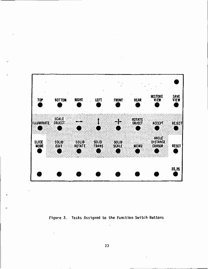
The FUNCTION SWITCH box contains thirty-two buttons. When any of the buttons is pressed, an action occurs or condition is set. Figure 3 depicts the functions programmed for each button. The buttons in the shaded area are used for editing while the rest are used for viewing the display. The exact functions assigned to these buttons will be discussed in the sections on viewing the display and on editing.
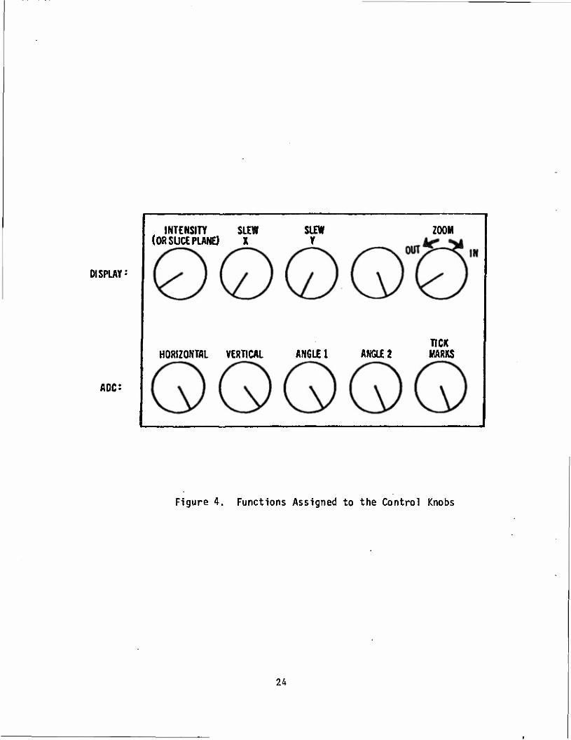
The CONTROL DIALS (knobs) are used to send digital information to the computer. As a knob is turned, a succession of numbers is available for use by the computer. Figure 4 depicts the functions assigned to each of the ten knobs. The exact functions of each of these knobs will be discussed in the angle distance cursor section and in the viewing features section.
The DATA TABLET is a graphics input device containing an X-Y coordinate grid which corresponds to the grid on the screen. Information is entered using a pen-like stylus. The distance this pen is from the tablet is important. If the pen tip is within one half inch of the tablet surface, the cursor location on the screen corresponds to the X,Y location of the pen on the tablet. This condition is called the "near" position. If the pen is more than one half inch from the tablet surface, the cursor remains located in the center of the screen. When the pen is pressed against the tablet surface, the pressure switch is activated and a bit is set which is a signal used by GED. The exact meaning of the pen near and pen press depends on what Is being done and will be covered in the appropriate sections of this report.
IX. ANGLE DISTANCE CURSOR (ADC)
The angle distance cursor is a construction aid used to measure angles and distances. It should be noted that all measurements are made In the projected space of the screen, so one should measure only in a view normal to the surface where the measurement is to take place. The ADC is placed on (or removed from) the display by pushing the "ADC" function switch button, (See Figure 3.) The ADC consists of three cursors which cover the entire screen. Figure 5 depicts the ADC as it
22
RESTORE SAVE TOP BOTTOM RIGHT l£FT FRONT REAR VIEW VIEW
lLLUMlfiÄtE:=:=:OBJECT:
SLICE iS&'SÖU* MODE :;:;:;> iEDlT:'
SOLID: ROTATE:
SOLID TRANS
SOLID SCALE
>>>:. 0BJECT>:>>; ACCEPT \
tfwx-VW STANCE MENÜ:::xv CURSOR::
REJECT
RESET
35,25
Figure 3. Tasks Assigned to the Function Switch Buttons
23
INTENSITY SLEW (OR SLICE PLANE) X
SLEW Y
ZOOM
DISPLAY
HORIZONTAL VERTICAL ANGLE 1 ANGLE 2 TICK MARKS
ADC:
Figure 4. Functions Assigned to the Control Knobs
24
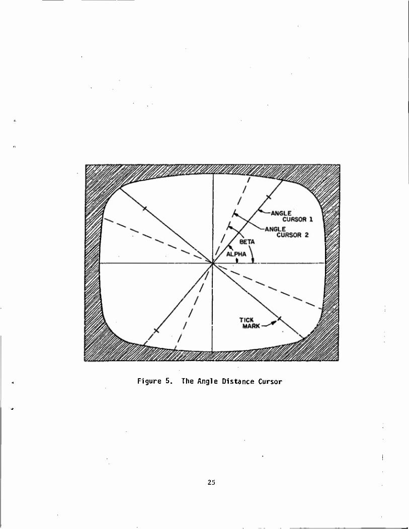
Figure 5. The Angle Distance Cursor
25
appears on the screen. All the cursors are centered at the sane point and can be moved to any location on the screen. Two of these cursors rotate for angle measuring purposes. Angle cursor 1 is solid while angle cursor 2 is dashed. Angle cursor 1 has movable tic marks for measuring distances on the screen. The two angle cursors move with the horizontal and vertical lines of the main cursor. The resulting effect is the moving of the center point horizontally or vertically. The ADC is controlled by the bottom row of the control dial knobs (Figure 4):
Knob 6 moves the center in the horizontal direction Knob 7 moves the center in the vertical direction Knob 8 rotates angle cursor 1 (alpha) Knob 9 rotates angle cursor 2 (beta) Knob 10 moves the tic marks
Whenever the ADC is on the screen, there is a readout at the bottom of the screen listing pertinent information about the ADC. This information includes the angles that angle cursors 1 and 2 have been rotated (alpha and beta), the distance the tic marks are from the center of the ADC, and the location of the center of the ADC. This information is continually updated on the screen.
X. VIEWING FUNCTIONS
The GED viewing features are designed to allow one to examine a target description in close detail. Any of the viewing features can be invoked at any time. It should be noted that these functions do not change the actual data, only the way these data are displayed.
Six standard views (front, rear, top, bottom, left, and right) and one oblique view (azimuth 35, elevation 25) are each assigned to the function buttons. (See Figure 3.) Hence, any of these views is immediately available at the press of the appropriate function button. The views available are not limited to these standard views, however, as the display can be rotated to any view by using the joystick. By pressing the function button labeled "save view" (Figure 3), the present viewing aspect angle of the display ts saved. At any time, the saved view can be immediately returned to the screen by pressing the "restore view" function button. (See Figure 3.) The "restore view" button will be lit whenever a view has been saved. The function button labeled "reset" (Figure 3) restores the display to the default view (front) when pressed.
The display can be panned or slewed on the screen tn two ways - using the data tablet and pen or by using the control knobs. When one is editing, the tablet and pen are not available for slewing; hence, one must use the control knobs to slew the display. If one is NOT editing, then whenever the pen is pressed, the display moves in the direction of an imaginary vector drawn from the center of the screen to the cursor location on the screen. Recall that there ts a one-to-one correspondence between the pen location and the cursor location. The longer this vector, the faster the display will move. To slew the display using the control knobs, one uses the knobs labeled "slew x" or
26
"slew y,"(See Figure 4.) The null positions on these knobs is in the center or straight up. If the "slew x" knob is turned clockwise of center, the display will move to the right« If it is turned counterclockwise, the display will move to the left. For the "slew y" control knob, clockwise of the center moves the display up and counterclockwise moves the display down. The further these knobs are turned from center, the faster the display moves.
One can zoom the display by using the control knob labeled "zoom." (See Figure 4.) Again, the null position of this knob is center or straight up. Turning this knob clockwise of center causes the display to increase in size» producing a zoom-in effect. Turning this knob counterclockwise of center causes the display to decrease in size or zoom out. Again, the further the "zoom" knob is turned from center, the faster the zooming will occur.
The viewing features of GED also include a slice mode. To invoke the slice feature, one presses the "slice mode" function button. (See Figure 3.) An imaginary slicing plane, parallel to the screen, can then be moved about by turning the first control knob. (See Figure 4.) Turning this knob clockwise moves the imaginary plane into the screen, and counterclockwise moves the plane out of the screen. All portions of the display in front of the plane are eliminated from the display. The result of moving this plane into the screen is a slicing effect with the parts of the display closest disappearing first. To leave the slice mode, just press the "slice mode" button again.
XI. SELECTING OBJECTS FOR EDITING
Before we discuss the editing features of GED, we will discuss how one selects objects for editing. To be edited, an object must be displayed on the screen. Since the object to be edited may be only a small portion of the display» a procedure is needed to select an object from the many objects being displayed. This procedure relies on the hierarchical structure of the GED data base. As stated before, when objects are displayed, every path of every object is traversed and the bottom object, which is always a solid, is drawn. Hence, one can think of each solid drawn not as one solid, but as the unique path used to reach that solid- As an example, the six paths (solids) for the sample object "heround" were presented in Table II.
To select an object for editing, one first must enter the illuminate mode by pressing the function button labeled "illuminate." (See Figure 3.) The data tablet and pen are then used to select the object. The surface of the data tablet is divided into imaginary horizontal strips. Each of these strips corresponds to a path (solid) drawn on the screen. For example, if the sample "heround" were displayed, the tablet surface would be divided into six horizontal strips. The pen is used in the "near" mode (within one half inch of tablet surface) to illuminate the paths. The path corresponding to the pen location is written in the upper right-hand corner of the screen. The solid at the bottom of this path is illuminated (drawn brighter) on the screen. In this manner one can "scan" the complete display by
27
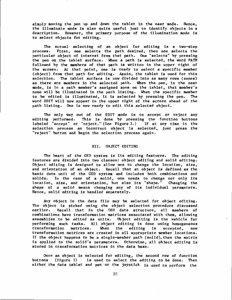
simply moving the pen up and down the tablet in the near mode. Hence, the illuminate mode is also quite useful just to identify objects in a description. However, the primary purpose of the Illumination mode is to select objects for editing.
The actual selecting of an object for editing is a two-step process. First, one selects the path desired, then one selects the particular object of interest from that path. One "selects" by pressing the pen on the tablet surface. When a path is selected, the word PATH followed by the members of that path is written in the upper right of the screen. At that point, one is ready to select a specific member (object) from that path for editing. Again, the tablet is used for this selection. The tablet surface is now divided into as many rows (zones) as there are members in the selected path. When the pen, in the near mode, is in a path member's assigned zone on the tablet, that member's name will be illuminated in the path listing. When the specific member to be edited is illuminated, it is selected by pressing the pen. The word EDIT will now appear in the upper right of the screen ahead of the path listing. One is now ready to edit this selected object.
The only way out of the EDIT mode is to accept or reject any editing performed. This is done by pressing the function buttons labeled "accept" or "reject." (See Figure 3.) If at any time in the selection process an Incorrect object is selected, just press the "reject" button and begin the selection process again.
XII. OBJECT EDITING
The heart of the GED system is its editing features. The editing features are divided into two classes: object editing and solid editing. Object editing is designed to allow one to change the location, size, and orientation of an object. Recall that an object is defined as the basic data unit of the GED system and includes both combinations and solids. In the case of a solid, one needs to change not only its location, size, and orientation, but also its "shape." Changing the shape of a solid means changing any of its Individual parameters. Hence, solid editing is handled separately.
Any object in the data file may be selected for object editing. The object is picked using the object selection procedure discussed earlier. Recall that in the GED data structure, all members of combinations have transformation matrices associated with them, allowing assemblies to be edited as units. Object editing is the vehicle for performing such tasks. All object editing is done using homogeneous transformation matrices. When the editing is accepted, new transformation matrices are created in all appropriate member locations. If the object happens to be a single-member path (solid), then the matrix is applied to the solid's parameters. Otherwise, all object editing is stored in transformation matrices in the data base.
Once an object is selected for editing, the second row of function buttons (Figure 3) is used to select the editing to be done. Then either the data tablet and pen or the joystick is USed to perform the
2C
actual editing.
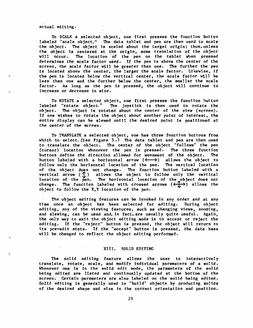
To SCALE a selected object, one first presses the function button labeled "scale object." The data tablet and pen are then used to scale the object. The object is scaled about the target origin; thus, unless the object is centered at the origin, some translation of the object will occur. The location of the pen on the tablet when pressed determines the scale factor used* If the pen is above the center of the screen, the scale factor will be greater than one. The further the pen is located above the center, the larger the scale factor. Likewise, if the pen is located below the vertical center, the scale factor will be less than one and the further below the center, the smaller the scale factor. As long as the pen is pressed, the object will continue to increase or decrease in size.
To ROTATE a selected object, one first presses the function button labeled "rotate object." The joystick is then used to rotate the object. The object is rotated about the center of the view (screen). If one wishes to rotate the object about another point of interest, the entire display can be slewed until the desired point is positioned at the center of the screen*
To TRANSLATE a selected object, one has three function buttons from which to select. (See Figure 3 .) The data tablet and pen are then used to translate the object. The center of the object "follows" the pen (cursor) location whenever the pen is pressed. The three function buttons define the direction allowed for movement of the object. The button labeled with a horizontal arrow (<• >) allows the object to follow only the horizontal location of the pen. The vertical location of the object does not change. The function button labeled with a vertical arrow ( T) allows the object to follow only the vertical location of the pen. The horizontal location of the object does not change. The function labeled with crossed arrows (C T >) allows the object to follow the X,Y location of the pen.
The object editing features can be invoked in any order and at any time once an object has been selected for editing. During object editing, any of the viewing features, such as changing views, zooming, and slewing, can be used and, in fact, are usually quite useful. Again, the only way to exit the object editing mode is to accept or reject the editing. If the "reject" button is pressed, the object will return to its pre-edit state. If the "accept" button is pressed, the data base will be changed to reflect the object editing performed.
XIII. SOLID EDITING
The solid editing feature allows the user to interactively translate, rotate, scale, and modify Individual parsmeters of a solid* Whenever one is in the solid edit mode, the parameters of the solid being edited are listed and continually updated at the bottom of the screen. Certain parameters are also labeled on the solid being edited. Solid editing is generally used to "build" objects by producing solids of the desired shape and size in the correct orientation and position.
29
Once the object is built, object editing is used to scale, orient, and position the object in the description. The general philosophy of solid editing is to first create a copy of a prototype solid with the desired name and then to edit this solid. The prototype solids should not be edited. As an example, suppose one were to build the sample object "heround" mentioned earlier. To produce the base of the shell, one would need a cylindrical shaped solid. The prototype solid is the TGC (Table 1), so one would type:
c tgc shellcase.s
A new solid record called shellcase.s would be created and displayed on the screen. This shellcase.s solid would then be edited using solid editing to produce the exact solid parameters desired. The solid record tgc would be unchanged and available for copying the next time a cylindrical solid is needed.
The procedure for solid editing is quite similar to that for object editing. First, the solid must be selected for editing. A solid is selected for editing using the illuminate mode, just as In object editing, except a solid must be selected. Recall that the bottom object in every hierarchy path is a solid. Second, one must push the function button labeled "solid edit." (See Figure 3.) This button sets up the solid edit mode: the solid parameters are listed at the bottom of the screen, pertinent solid parameters are labeled on the display, the solid editing function buttons are activated, and a menu header depending on the solid type is written on the right side of the screen. The meaning of the menu will be discussed shortly. Third, one selects (by pressing the appropriate function buttons) and performs the editing desired. Finally, one exits the solid editing mode by accepting or rejecting the editing performed, just as in object editing.
Recall, in the section on object editing it was mentioned that since a solid is indeed an object, a solid can be edited (translated, rotated, and scaled) as an object. Hence, the solid editing mode is really only necessary to perform parameter modifications. However, much of the object editing is done about the target or screen center, which can be annoying when editing a solid. Also, precise parameter modifications are possible (using the "p" keyboard command) in solid editing. Thus, it was deemed desirable to include translation, rotation, and scaling in solid editing also.
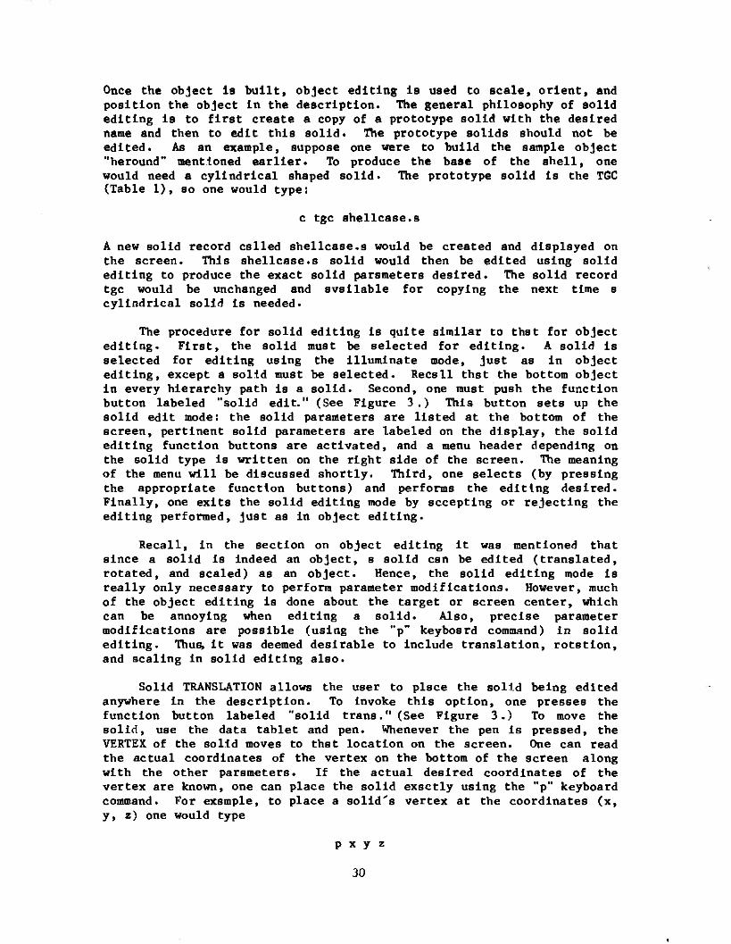
Solid TRANSLATION allows the user to place the solid being edited anywhere in the description. To invoke this option, one presses the function button labeled "solid trans." (See Figure 3.) To move the solid, use the data tablet and pen. Whenever the pen is pressed, the VERTEX of the solid moves to that location on the screen. One can read the actual coordinates of the vertex on the bottom of the screen along with the other parameters. If the actual desired coordinates of the vertex are known, one can place the solid exactly using the "p" keyboard command. For example, to place a solid's vertex at the coordinates (x, y, z) one would type
p x y z
30
The solid would then jump to this location.
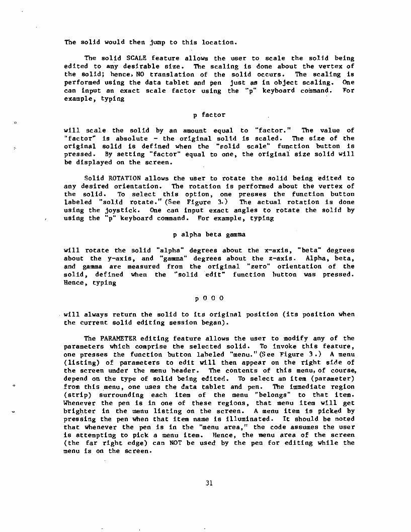
The solid SCALE feature allows the user to scale the solid being edited to any desirable size. The scaling Is done about the vertex of the solid; hence» NO translation of the solid occurs. The scaling Is performed using the data tablet and pen just as In object scaling. One can Input an exact scale factor using the "p" keyboard command. For example, typing
p factor
will scale the solid by an amount equal to "factor." The value of "factor" Is absolute - the original solid Is scaled. The size of the original solid is defined when the "solid scale" function button Is pressed. By setting "factor" equal to one, the original size solid will be displayed on the screen.
Solid ROTATION allows the user to rotate the solid being edited to any desired orientation. The rotation is performed about the vertex of the solid. To select this option, one presses the function button labeled "solid rotate." (See Figure 3.) The actual rotation is done using the joystick. One can input exact angles to rotate the solid by using the "p" keyboard command. For example, typing
p alpha beta gamma
will rotate the solid "alpha" degrees about the x-axis, "beta" degrees about the y-axis, and "gamma" degrees about the z-axis. Alpha, beta, and gamma are measured from the original "zero" orientation of the solid, defined when the "solid edit" function button was pressed. Hence, typing
p 0 0 0
will always return the solid to its original position (its position when the current solid editing session began).
The PARAMETER editing feature allows the user to modify any of the parameters which comprise the selected solid. To invoke this feature, one presses the function button labeled "menu."(See Figure 3.) A menu (listing) of parameters to edit will then appear on the right side of the screen under the menu header. The contents of this menu» of course, depend on the type of solid being edited. To select an item (parameter) from this menu, one uses the data tablet and pen. The immediate region (strip) surrounding each item of the menu "belongs" to that item. Whenever the pen is In one of these regions, that menu item will get brighter in the menu listing on the screen. A menu item Is picked by pressing the pen when that item name is illuminated. It should be noted that whenever the pen is in the "menu area," the code assumes the user is attempting to pick a menu item. Hence, the menu area of the screen (the far right edge) can NOT be used by the pen for editing while the menu is on the screen.
31
For parameter editing, the solid type determines the menu items. The GED code recognizes four general solid types for parameter editing. All the specific solid types which fall into one of these general classes are treated as the general type. For example, all the cylindrical solid types are treated as the general type - the TGC. In the following paragraphs, we will discuss parameter editing for each of these general types of solids.
A. ARB PARAMETER EDITING
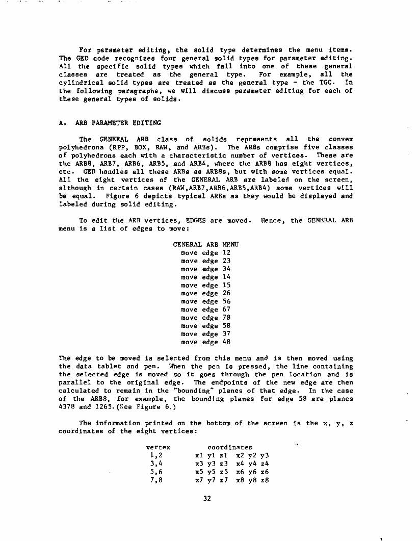
The GENERAL ARB class of solids represents all the convex polyhedrons (RPP, BOX, RAW, and ARBs). The ARBs comprise five classes of polyhedrons each with a characteristic number of vertices. These are the ARB8, ARB7, ARB6, ARB5, and ARBA, where the ARB8 has eight vertices, etc. GED handles all these ARBs as ARB8s, but with some vertices equal. All the eight vertices of the GENERAL ARB are labeled on the screen, although in certain cases (RAW,ARB7,ARB6,ARB5,ARBA) some vertices will be equal. Figure 6 depicts typical ARBs as they would be displayed and labeled during solid editing.
To edit the ARB vertices, EDGES are moved. Hence, the GENERAL ARB menu is a list of edges to move:
GENERAL ARB MENU move edge 12 move edge 23 move edge 3A move edge 1A move edge 15 move edge 26 move edge 56 move edge 67 move edge 78 move edge 58 move edge 37 move edge A8
The edge to be moved is selected from this menu and is then moved using the data tablet and pen. When the pen is pressed, the line containing the selected edge is moved so it goes through the pen location and is parallel to the original edge. The endpoints of the new edge are then calculated to remain in the "bounding" planes of that edge. In the case of the ARB8, for example, the bounding planes for edge 58 are planes A378 and 1265.(See Figure 6.)
The information printed on the bottom of the screen is the x, y, z coordinates of the eight vertices:
vertex coordinates 1,2 xl yl zl x2 y2 y3 3,A x3 y3 z3 xA yA zA 5,6 x5 y5 z5 x6 y6 z6 7,8 x7 y7 z7 x8 y8 z8
32
8
3
5
BOX
ARB8
ARB7
5,6,7,8 ARB6
ARB4
Figure 6. Typical Generalized ARBs
33
These values are continually updated during solid editing.
The user can force the line containing an edge through any point using the "p" keyboard command. Hence, typing
p x y z
will force the line containing the edge being edited to pass through the point (x, y, z). No check is made for concave ARBs or for ARBs with crossed edges. Visual feedback from the display is considered adequate to detect these situations.
B. TGC PARAMETER EDITING
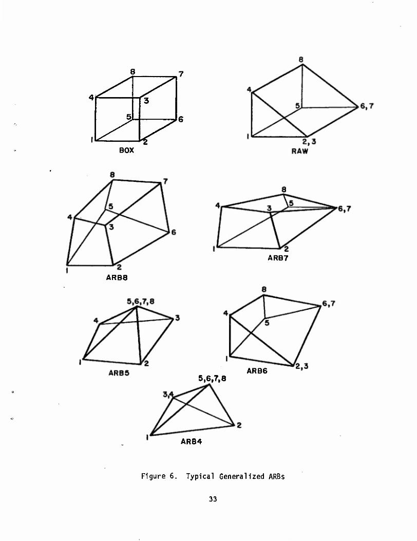
The TGC general class of solids includes all the cylindrical COMGEOM solids. The defining parameters of the TGC are two base vectors (A and B), a height vector (H), two top vectors (C and D), and the vertex (V). Reference 1 contains more information on these parameters. The top vectors C and D are directed the same as the base vectors A and B, respectively; hence, the top vectors are defined only by their lengths (c and d). Figure 7 depicts these parameters on typical TGCs. When a TGC is edited in the solid editing mode, only vectors A and B are labeled on the display.
All the vectors (A,B,C,D,H) of the TGC can be scaled during parameter editing. In addition, the height vector (H) and the base (AxB) can be rotated. These parameter editing options are reflected in the TGC menu:
TGC MENU scale H scale A scale B scale c scale d rotate H
rotate AxB
The scaling of the lengths of the vectors is done using the data tablet and pen in the same manner as object editing. Exact vector lengths can be achieved easily using the "p" keyboard command. If one is scaling a vector, then typing
P x
will make the vector being scaled have a length equal to "x."
To rotate vector H or surface AxB, one uses the joystick. Since vectors C and D have the same direction as vectors A and B, respectively, the top and bottom surfaces of the TGC will remain parallel. Hence, rotating the base surface (AxB) will also rotate the top surface. The "p" keyboard command is not used with the parameter rotation of the TGC.
34
RCC TRC
TEC
Figure 7. Typical TGCs
35
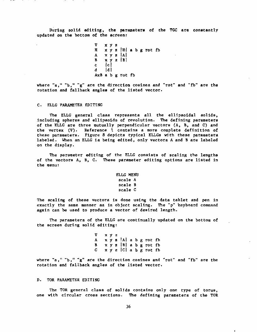
During solid editing, the parameters of the TGC are constantly updated on the bottom of the screen;
V x y z H x y z IHI a b g rot fb A x y z |A| B x y z lB| c |c| d |d| AxB a b g rot fb
where "a," "b," "g" are the direction cosines and "rot" and "fb" are the rotation and fallback angles of the listed vector.
C. ELLG PARAMETER EDITING
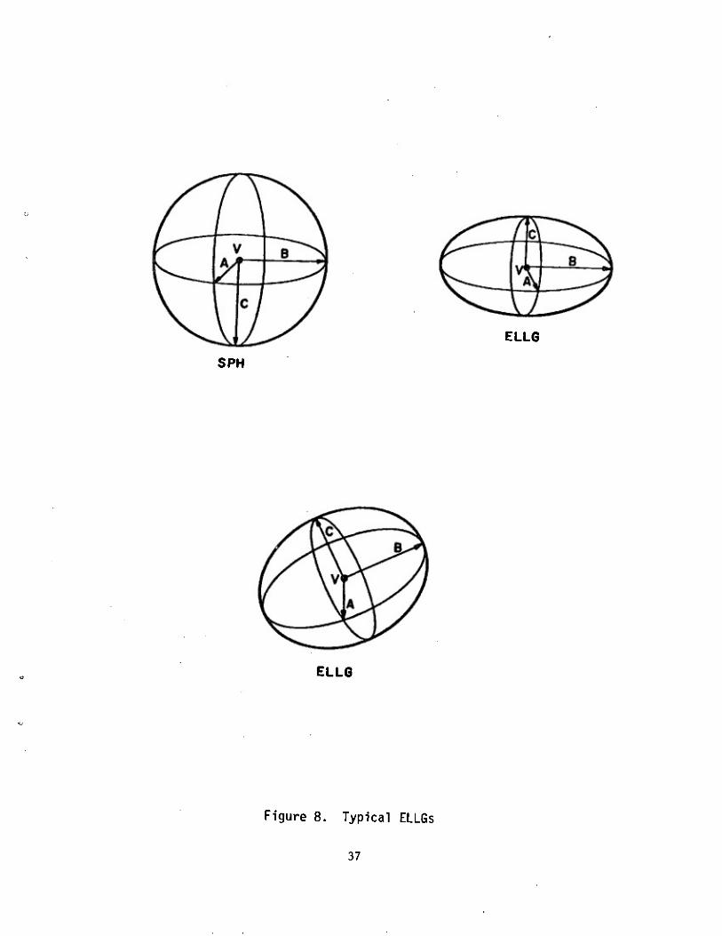
The ELLG general class represents all the ellipsoidal solids, .including spheres and ellipsoids of revolution. The defining parameters of the ELLG are three mutually perpendicular vectors (A, B, and C) and the vertex (V). Reference l contains a more complete definition of these parameters. Figure 8 depicts typical ELLGs with these parameters labeled. When an ELLG is being edited, only vectors A and B are labeled on the display.
The parameter editing of the ELLG consists of scaling the lengths of the vectors A, B, C. These parameter editing options are listed in the menu:
ELLG MENU scale A scale B scale C
The scaling of these vectors is done using the data tablet and pen in exactly the same manner as in object scaling. The "p" keyboard command again can be used to produce a vector of desired length.
The parameters of the ELLG are continually updated on the bottom of the screen during solid editing:
V x y z A xyz|A|abg rot fb B x y z |B| a b g rot fb C xyzlcjabg rot fb
where "a," "b," "g" are the direction cosines and "rot" and "fb" are the rotation and fallback angles of the listed vector.
D. TOR PARAMETER EDITING
The TOR general class of solids contains only one type of torus, one with circular cross sections. The defining parameters of the TOR
36
SPH
ELL6
ELLG
Figure 8. Typical ELLGs
37
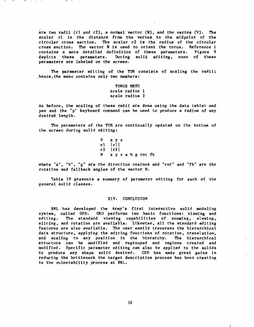
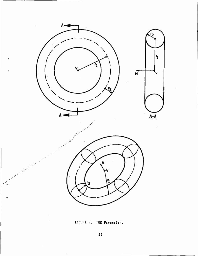
are two radii (rl and r2), a normal vector (N), and the vertex (V). The scalar rl is the distance from the vertex to the midpoint of the circular cross section. The scalar r2 is the radius of the circular cross section. The vector N is used to orient the torus. Reference 1 contains a more detailed definition of these parameters. Figure 9 depicts these parameters. During solid editing, none of these parameters are labeled on the screen.
The parameter editing of the TOR consists of scaling the radii; hence,the menu contains only two members:
TORUS MENU scale radius 1 scale radius 2
As before, the scaling of these radii are done using the data tablet and pen and the "p" keyboard command can be used to produce a radius of any desired length.
The parameters of the TOR are continually updated on the bottom of the screen during solid editing:
V x y z rl |rl| r2 |r2| N x y z a b g rot fb
where "a", "b", "g" are the direction cosines and "rot" and "fb" are the rotation and fallback angles of the vector N.
Table IV presents a summary of parameter editing for each of the general solid classes.
XIV. CONCLUSION
BRL has developed the Army's first interactive solid modeling system, called GED. GED performs two basic functions: viewing and editing. The standard viewing capabilities of zooming, slewing, slicing, and rotation are available. Likewise, all the standard editing features are also available. The user easily traverses the hierarchical data structure, applying the editing functions of rotation, translation, and scaling to any position in the hierarchy. The hierarchical structure can be modified and regrouped and regions created and modified. Specific parameter editing can also be applied to the solids to produce any shape solid desired. GED has made great gains in reducing the bottleneck the target description process has been creating In the vulnerability process at BRL.
38
N
.-"
s
Figure 9. TOR Parameters
39
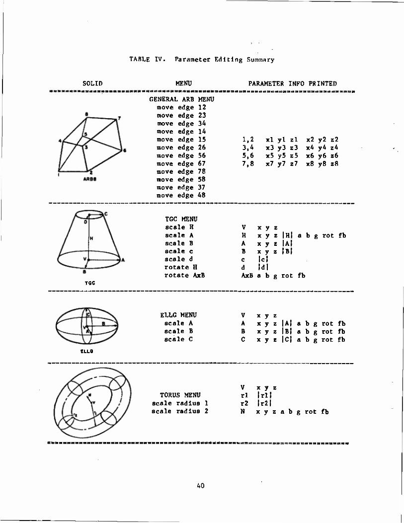
TABLE IV. Parameter Editing Summary
SOLID MENU PARAMETER INFO PRINTED
GENERAL ARB move edge move edge move edge move edge move edge move edge move edge move edge move edge move edge move edge move edge
MENU 12 23 34 14 15 26 56 67 78 58 37 48
1,2 xl yl zl x2 y2 z2 3,4 x3 y3 z3 x4 y4 z4 5,6 x5 y5 z5 x6 y6 z6 7,8 x7 y7 z7 x8 y8 z8
TOC
TGC MENU scale H scale A scale B scale c scale d rotate H rotate AxB
V H A B c d AxB
x y x y x y x y Ic| Id! a b
IHI Ul IBI
b g rot fb
g rot fb
ELLG MENU V scale A A scale B B scale C C
x y z x y z |A| a b g rot fb x y z |B| a b g rot fb x y z 101 a b g rot fb
ELLO
V x y z TORUS MENU rl Irll
scale radius 1 r2 lr2| scale radius 2 N x y z a b g rot fb
40
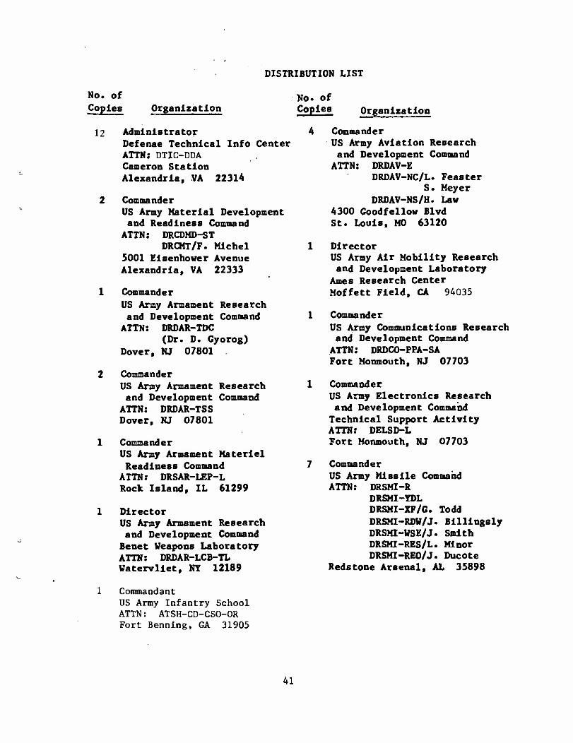
DISTRIBUTION LIST
No. of Copies
12
Organization
Administrator Defense Technical Info Center ATTN: DTIC-DDA Cameron Station Alexandria, VA 22314
Commander US Army Material Development and Readiness Command
ATTN: DRCDMD-ST DRCMT/F. Michel
5001 Elsenhower Avenue Alexandria, VA 22333
Commander US Army Armament Research and Development Command
ATTN: DRDAR-TDC (Dr. D. Gyorog)
Dover, NJ 07801
Commander US Army Armament Research and Development Command
ATTN: DRDAR-TSS Dover, NJ 07801
Commander US Army Armament Materiel
Readiness Command ATTN: DRSAR-LEP-L Rock Island, IL 61299
Director US Army Armament Research and Development Command Benet Weapons Laboratory ATTN: DRDAR-LCB-TL Watervliet, NY 12189
Commandant US Army Infantry School ATTN: ATSH-CD-CS0-0R Fort Benning, GA 31905
No. of Copies Organization
Commander US Army Aviation Research and Development Command
ATTN: DRDAV-E DRDAV-NC/L. Feaster
S. Meyer DRDAV-NS/H. Law
4300 Goodfellow Blvd St. Louis, MO 63120
Director US Army Air Mobility Research and Development Laboratory
Ames Research Center Moffett Field, CA 94035
Commander US Army Communications Research and Development Command
ATTN: DRDCO-PPA-SA Fort Monmouth, NJ 07703
Commander US Army Electronics Research and Development Command Technical Support Activity ATTN: DELSD-L Fort Monmouth, NJ 07703
Commander US Army Missile Command ATTN: DRSMI-R
DRSMI-YDL DRSMI-XF/G. Todd DRSMI-RDV/J. Billlngsly DRSMI-VSE/J. Smith DRSMI-RES/L. Minor DRSMI-RE0/J. Ducote
Redstone Arsenal, AL 35898
41
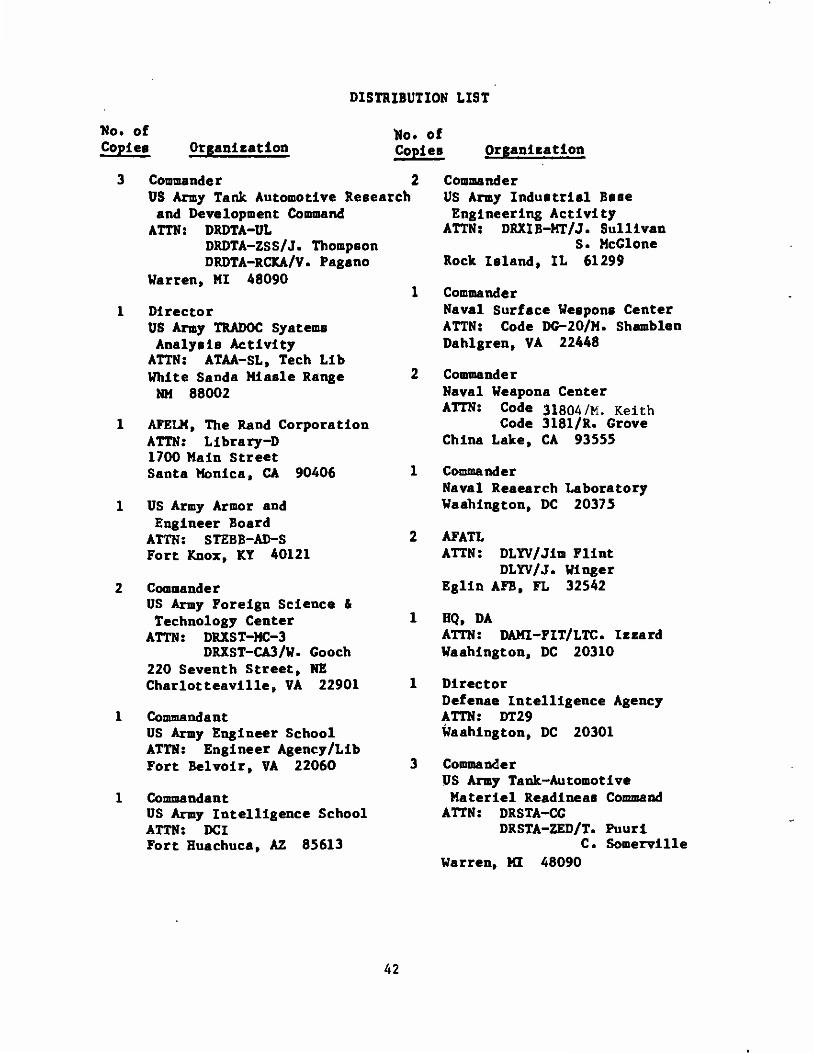
DISTRIBUTION LIST
flo. of Copies Organleatlon
Ko. of Copies
Commander 2 US Army Tank Automotive Research and Development Command
ATTN: DRDTA-UL DRDTA-ZSS/J. Thompson DRDTA-RCKA/V. Pagano
Warren, MI 48090
Director US Army TRADOC Systems Analysis Activity
ATTN: ATAA-SL, Tech Lib White Sands Mlssle Range NM 88002
AFELM, The Rand Corporation ATTN: Library-D 1700 Main Street Santa Monica, CA 90406
US Army Armor and Engineer Board
ATTN: STEBB-AD-S Fort Knox, KY 40121
Commander US Army Foreign Science & Technology Center
ATTN: DRXST-MC-3 DRXST-CA3/W- Cooch
220 Seventh Street, NE Charlottesvllle, VA 22901
Commandant US Army Engineer School ATTN: Engineer Agency/Lib Fort Belvolr, VA 22060
Commandant US Army Intelligence School ATTN: DCI Fort Huachuca, AZ 85613
1
Organisation
Commander US Army Industrial Base Engineering Activity
ATTN: DRXIB-MT/J. Sullivan S. McGlone
Rock Island, IL 61299
Commander Naval Surface Weapons Center ATTN: Code DG-20/M. Shamblen Dahlgren, VA 22448
Commander Naval Weapons Center ATTN: Code 31804/M. Keith
Code 3181/R. Grove China Lake, CA 93555
Commander Naval Research Laboratory Washington, DC 20375
AFATL ATTN: DLYV/Jlra Flint
DLYV/J. Winger Eglln AFB, FL 32542
HQ, DA ATTN: DAMI-FIT/LTC. Izzard Washington, DC 20310
Director Defense Intelligence Agency ATTN: DT29 Washington, DC 20301
Commander US Army Tank-Automotive Materiel Readiness Command
ATTN: DRSTA-CG DRSTA-ZED/T. Puuri
C. Somervilie Warren, MI 48090
42
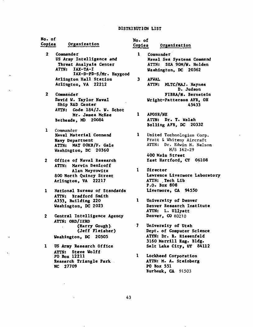
DISTRIBUTION LIST
No. Of Copies Organization
Commander US Army Intelligence and Threat Analysis Center
ATTN: IAX-TA-I IAX-D-PD-S/Mr. Haygood
Arlington Hall Station Arlington» VA 22212
Commander David W. Taylor Naval Ship R&D Center
ATTN: Code 184/J. W. Schot Mr. James McKee
Bethesda, MD 20084
Commander Naval Material Command Navy Department ATTN: MAT 00KB/F. Gale Washington, DC 20360
Office of Naval Research ATTN: Marvin Denlcoff
Alan Meyrowltz 800 North Qulncy Street Arlington, VA 22217
National Bureau of Standards ATTN: Bradford Smith A353, Building 220 Washington, DC 2023
Central Intelligence Agency ATTN: ORD/IERD
(Harry Gough) (Jeff Flelsher)
Washington, DC 20505
US Army Research Office ATTN: Steve Wolff P0 Box 12211 Research Triangle Park NC 27709
No. of Copies Organization
1 Commander Naval Sea Systems Command ATTN: SEA 90M/W. Holden Washington, DC 20362
3 AFWAL ATTN: MLTC/MAJ. Haynes
D. Judson FIBRA/N. Bernstein
Wright-Patterson AFB, OH 45433
1 AF0SR/NE ATTN: Dr. T. Walsh Boiling AFB, DC 20332
1 United Technologies Corp. Pratt & Whiteny Aircraft ATTN: Dr. Edwin N. Nelson
M/S 162-29 400 Main Street East Hartford, CT 06108
1 Director Lawrence Livermore Laboratory ATTN: Tech Lib P.O. Box 808 Livermore, CA 94550
1 University of Denver Denver Research Institute ATTN: L. Ullyatt Denver, CO 80210
7 University of Utah Dept. of Computer Science ATTN: Dr. R. Riesenfeld 3160 Merrill Eng. Bldg. Salt Lake City, UT 84112
1 Lockheed Corporation ATTN: M. A. Steinberg P0 Box 551 Burbank, CA 91503
43
DISTRIBUTION LIST
No. of Copies Organization
No. Of Copies Organization
System Planning Corp. ATTN; T. Hafer
A« Hafer 1500 Wilson Boulevard Arlington, VA 22209
Evans & Sutherland ATTN: Cralg Rasmussen 580 Arapeen Drive Salt Lake City, UT 84108
3 MAGI ATTN: R. Goldstein
M. Cohen H. Steinberg
3 Weetcheeter Plaza Elmsford, NY 10523
General Motors Corp. Research Laboratories
ATTN: John Boyse John Joyce
Warren, Michigan 48090
General Dynamics Data Systems Services ATTN: Richard Frldehal P0 Box 80847 San Diego, CA 92138
TASC ATTN: Paula Hagan 1 Jacob Way Reading, MA 01867
SDRC ATTN: Robert Ard 2000 Eastman Drive Mllford, OH 45150
Computervision ATTN: Dr. V. Gelsberg
Dr. R. Hlllyard 201 Burlington Road Bedford, MA 01730
Megatek Corp. ATTN: M. Landguth
S. Bryant J. Prohaska
888 Washington Street Dedham, MA 02026
Lockheed-California Co. ATTN: Richard Rlccl Burbank, CA 91520
John Fluke Mfg. Co., Inc. ATTN: D. Gunderson P0 Box C9090 Everett, WA 98206
A 0 SMITH Data Systems Division ATTN: H. Vlckeman 8901 N. Klldeer Court Brown Deer, WI 53209
Vought Corporation ATTN: Paul Chan P0 Box 225907 Dallas, Texas 75265
Sikorsky Aircraft ATTN: R. Welge North Main Street Stratford, Conn 06602
Rex L. Nelson 1K204 IBM 1133 Weetcheeter Ave White Plains, NY 10604
Appllcon Inc. ATTN: J,P. DeBernardo 32 Second Avenue Burlington, MA 01803
Lockheed-Georgia Co. ATTN: Joe Tulkoff Marietta, GA 30063
44
DISTRIBUTION LIST
No. of Copies Organization
DMI Data Inc. ATTN: H. Dicken 6900 E. Camelback Rd. Scottsdale, AZ 85251
Rensselaer Polytechnic Ins ATTN: Dr. M. Wozny Troy, NY 12181
1 IIT Research Institute ATTN: A. S. Baldwin 1825 K Street, N.W. Washington, DC 20006
1 General Electric Company ATTN: Ravi Kanuri 777 14th Street, N.W. Washington, DC 20005
3 Environmental Research Institute of Michigan
ATTN: Earl Cobb W. Hartman G. Darling
PO Box 8618 Ann Arbor, MI 48107
1 0LIN Technical Systems Operation ATTN: Everett Moore Drawer "G" Marion, IL 62959
1 SINGER Kearfott Division ATTN: J. Drossman 150 Totowa Road Wayne, NJ 07470
2 General Electric Company Computer Graphics Group ATTN: Virgil Lucke
Lon Jones Gchenectady, NY 12301
No. of Copies Organization
FMC Corporation Ordnance Division ATTN: J.E. Blllkam 1105 Coleman Ave. Box 1201 San Jose, CA 95108
Science Applications, Inc ATTN: Ron Weite 1710 Goodridge Drive Box 1303 McClean, VA 22102
Director NVLE0L ATTN: DELNN-VI/J. Ho Ft. Belvoir, VA 22060
Sandia Laboratories Computer Aids Systems ATTN: James Kelly Development 2424 Albuquerque, NM 87115
Director of Space Systems Headquarters Space Division ATTN: HQ SD/YNAA PO Box 92960 Worldway Postal Center Los Angeles, CA 90009
45
No. of Copies Organisation
ABERDEEN PROVING GROUND
Director USAMSAA ATTN: DRXSY-A/D. O'Nlell
A. Dorney DRXSY-C/E. Atzlnger DRXSY-D/W. Brooks
J. Kramer DRXSY-F/J. McCarthy
M. Reches DRXSY-GS/A, . Young DRXSY-GI/G, , HolIoway DRXSY-FR/L. . Bain DRXSY-R/R. Simmons DRXSY-T/A. Reld DRXSY-D , DRXSY-KP/H. Cohen
Commander USATECOM ATTN: DRSTE-TO-F
Director ÜSACSL, Bid«. E3516, EA ATTN: DRDAR-CLB^PA
DRDAR-CLN _. _ DRDAR-CLJ-L Director I
USAHEL
Director MTD
DISTRIBUTION LIST
No. of Copies Organization
46