Embed Size (px)
Citation preview

EE089/ANA/2B/080911
DIAGNOSIS OF STATOR INTER-TURN SHORT CIRCUIT IN DTC
INDUCTION MOTOR DRIVES
MIJIIAMAD FARANI BIN MUSTAFA
A report submitted in partial fulfillment of the
requirements for the award of the degree of
Bachelor of Electrical Engineering (Power System)
Faculty of Electrical And Electronics
Universiti Malaysia Pahang
NOVEMBER 2009
ABSTRACT
Faults in the stator windings of three-phase induction machines are recognized to
play a major role in the failures that occur during the machines life span. The machines
(or motors) which were fed by inverters tend to worsen its condition, due to the fast
switching of the power semiconductors used by the inverters in which promotes voltage
stresses. After a period of time the machines will be affected by the degradation of the
stator turns insulation which will eventually lead to winding short circuits. By
diagnosing the stator faults in DTC induction motor drives, we can then determine the
failures which the information could be used to construct an artificial intelligence system
that can help monitor and pin-point the source of motor failure. Thus overcoming the
problems is possible and further development of the machines can be done in the near
future.
iv
ABSTRAK
Kerosakan dalam gulungan stator motor induksi tiga fasa memainkan peranan
,utama dalam kegagalan yang berlaku selama jangka hayat mesin. Motor-motor yang
dijana olch inverter cenderung untuk mengalami kerosakan kerana peralihan cepat oleh
semikonduktor kuasa yang digunakan oleh inverter yang mempromosikan penekankan
voltan. Selepas tempoh masa tertentu, motor akan dipengaruhi oleh degradasi stator
yang akhirnya akan mengarah pada litar pintas. Dengan mendiagnosis kerosakan dalam
stator DTC motor induksi, kita botch menentukan kerosakan di mana makiumat yang
telah dikumpulkan boleh digunapakai untuk membina sebuah sistem kecerdasan buatan
yang dapat membantu memantau dan menunjukkan sumber kegagalan motor. Dengan
mi masalah-masalah yang timbul dapat diatasi dan pengembangan lanjut enjin boleh
dilakukan dalam waktu dekat.
V
TABLE OF CONTENTS
SUPERVISOR'S DECLARATION
STUDENT'S DECLARATION
ACKNOWLEDGEMENT
ABSTRACT iv
ABSTRAK v
TABLE OF CONTENTS vi
LIST OF TABLES vii
LISTOF FIGURES viii
CHAPTER 1: INTRODUCTION
Project Background 2
Problem Statement 2
Objectives 3
Project Scopes 3
Thesis Outline 4
CHAPTER 2: LITERATURE REVIEW
2.1 MOTOR 6
2.1.1 Induction Motors 6
2.2 CONTROLLER 8
2.2.1 Direct Torque Control (DTC) 8
A
2.3 INDUCTION MOTOR FAULTS 10

2.3.1 Stator Faults 10
2.4 SENSOR SIGNALS 12
.2.4.1 Vibration 12
2.4.2 Stator Current 12
2.4.3 Axial Magnetic Flux 12
2.4.4 Stator Voltage 13
2.4.5 Other Techniques 13
2.5 SIGNAL PROCESSING TECHNIQUE 14
2.5.IRMS 14
2.5.2 Frequency Analysis 14
2.5.3 Other Frequency Analysis Methods 14
2.6 ARTIFICIAL NEURAL NETWORK 16
CHAPTER 3: METHODOLOGY
3.1 DATA COLLECTION & MANIPULATION 20
3. 1.1 Construction Of Simulink Model: Induction Machine Parameters 20
3. 1. 1.1 Asynchronous Machine Block 20
3.1.1.2 Block Parameters 23
3.1.1.3 Inputs and Outputs 24
3.1.2 Construction Of Simulink Model: Signal Processing 27
3.. 1.2.1 Frequency Analysis Block 27
3.1.2.2 RMS Block 28
3.1.2.3 Block Construction 29
3.1.2.4 Block Placement 29
11.3 Constructed Simulink Model 30
3.1.4 Simulink Model Simulation 31
3.1.4.1 Simulation Parameters 31
3.1.4.2 Healthy State Simulation 32
3.1.4.3 Faulty State Simulation 34
3.2 DATA MANIPULATION: CONSTRUCTION OF NEURAL NETWORK 36
3.2.1 RBNN Construction 36
3.2.2 RBNN Build 38
3.3 DATA MANIPULATION: GUI CONSTRUCTION 40
3.3.l GUI Build 41
3.3.1.1 Input Parameters Panel 49
3.3.1.2 Stator Winding Condition Panel 50
13.1.3 Command Panel 50
3.3.1.4 Guide Panel 51
3.3. 1.5 About and Close Pushbuttons 52
3.3.1.6 Proposed GUI Construction 53
CHAPTER 4: RESULTS AND DISCUSSION
4.1 GRAPHICAL USER INTERFACE (GUT) 55
4.2 GUT OPERATION 56
4.2.1 GUI Operation: Healthy Motor Condition 56
4.2.2 GUI Operation: Faulty Motor Condition 57
4.2.3 GUI Operation: Error messages 60
42.4 GUT Operation: Example 61
4.2.5 GUT Operation: Instructions 62
4.2.6 GUT Operation: Parameters 63
4.2.7 GUT Operation: About 64
CHAPTERS: CONCLUSION AND RECOMMENDATION
5.lConclusion 66

5.2Assessment on design 66
5.3 Strength and Weakness 67
5.4Suggestion for Future Work
67
APPENDIX A GUI CODING
APPENDIX B REFERENCES 81
VII
LIST OF TABLES
Table 1 List of subscripts
21
Table 2 Table of Parameters 22
Table 3 Parameters of Asynchronous Machines
24
Table 4 Inputs and Outputs
24
Table 5 Signals Provided
25
Table 6 Fault Parameter 31

LIST OF FIGURES
Figure 1 Induction Motor 6
Figure 2 DTC Block Diagram 8
Figure 3 Induction Motor Faults 10
Figure 4 ANN Build 16
Figure 5 Methodology 19
Figure 6 Machine Block 20
Figure 7 Asynchronous Machine Block Parameters 23
Figure 8 Winding Representation 26
Figure 9 Torque Parameter 26
Figure 10 Winding Resistance 26
Figure 11 RMS Block 29
Figure 12 Block Placement 29
Figure 13 Load 32
Figure 14 Run Simulation 32
Figure 15 RMS Readings 33
Figure 16 Load 34
Figure 17 Winding Resistance 34
Figure 18 Run Simulation 35
Figure 19 RMS Reading 35
Figure 20 Healthy Data 38
Figure 21 Winding I Data 38
Figure 22 Winding 2 Data 39
Figure 23 Winding 3 Data 39
Figure 24 Target 39
Figure 25 GUIDE 40
Figure 26 GUIDE Start 41
vii

Figure 27 Blank workspace 42
Figure 28 Designed GUI 42
Figure 29 Property Inspector 43
Figure 30 rn-file editor 45
Figure 31 rn-file editor 46
Figure 32 rn-file editor 47
Figure 33 rn-file editor 48
Figure 34 rn-file editor 48
Figure 35 Input Parameters 49
Figure 36 Stator Winding Condition Panel 50
Figure 37 Command Panel 50
Figure 38 Guide Panel 51
Figure 39 About and Close pushbuttons 52
Figure 40 Constructed GUI 53
Figure 41 GUI 55
Figure 42 Insert parameters 56
Figure 43 Simulate 57
Figure 44 Faulty parameters 57
Figure 45 Error 58
Figure 46 Fault at Winding 2 58
Figure 47 Fault at Winding 2 59
Figure 48 Fault at Winding 3 59
Figure 49 Fault at Winding 3 60
Figure 50 Invalid 60
Figure 51 Not a number 61
Figure 52 maximum value 61
Figure 53 Example 61
Figure 54 Instructions 62
Figure 55 Parameters 63
Figure 56 About 64

CHAPTER 1
INTRODUCTION
Chapter Overview:
The title of this project is Diagnosis of Stator Inter Turn Short Circuit in DTC Induction
Motors. The monitoring and fault detection of DTC induction machines have moved in
recent years from traditional techniques to artificial intelligence (Al) techniques. Such
techniques require a minimum configuration intelligence since no detailed analysis of
the fault mechanism is necessary, nor is any modeling of the system required. When an
Al technique is used, fault detection and evaluation can be accomplished without a
human expert.
2
Induction motors play an important role in manufacturing environments,
therefore this type of machine is mainly considered and many diagnostic procedures are
proposed from industries. Some work has also been done on converter-fed induction
motor drives in order to realize a fault-tolerant drive avoiding shutdown if the load
conditions permit faults and failures.
This project is divided into 3 different tasks because it is mainly to collect data, analyze
and acknowledge the behavior of the motor condition and then determine the causes of
the fault occurrence. The main steps of a diagnostic procedure can be classified as
follows:
1) Data Collection
2) Data Manipulation
3) Data Implementation
Project Background
Artificial intelligence techniques have proved their ability in detection of
incipient faults in electrical machines. In this project, the fault diagnosis of three phase
induction motors is studied using models and neural networks have been used in the
fault diagnosis of induction motors using Radial Basis Neural Network (RBNN) in
MATLAB.
Problem Statement
The increased in demand has greatly improved the approach of fault detection in
induction motors. Nowadays artificial intelligence is implemented to improve traditional
techniques, where the results can be obtained instantaneously after it analyzes the input
data of the motor.
Artificial intelligence approached can easily do difficult analysis such as pattern
recognition and nonlinear system identification and control. In this project, Radial Basis

Cl
Neural Network is used to train data and analyzes the condition of the motor. The neural
network is then would be used as a tool to investigate the conditions of the winding by
comparing the actual data to the database (offline monitoring).
Objectives
The Diagnosis of Stator Inter Turn Short Circuit in DTC Induction Motors is developed
with the listed objectives below:
To develop and create a new reliable technique by using artificial intelligence to
detect stator inter turn short circuit in DTC induction motor.
• To apply basic knowledge on Artificial Neural Network Tools in MATLAB.
• To train radial basis function to produce output whether there are no fault or
stator fault for three-phase induction motor.
Project Scopes
There are several scopes for the project:
• Radial Basis Neural Network (RBNN) approach will be used for Artificial
Neural Network training and test.
• This project is use to detect faults in three phase DTC induction motors only. It is
the most popular induction motor in industry.
• Limited to detect stator inter turn faults only.
4
Thesis Outline
This thesis consists of five chapters. In the first chapter, this chapter discussed
the overall idea of this project including objectives of project, problem statement, the
scope of this project and summary of this thesis.
Chapter 2 discussed more on theory and literature review that have been done. It
is well discusses about the ANN, basic concept of the fault in induction motor, Radial
Basis Function network and parameters related to this project.
Chapter 3 described briefly the methodology of the data extraction, fault
evaluation and ANN development for this project. The figures, tables and extra
information are aided into this chapter to he the benchmark thesis in development of
Radial Basis Function Neural Network in detection of stator inter turn fault in the DTC
induction motor.
Chapter 4 presents :a discussion of the implementation, result and analysis of the
whole project. This chapter also explains the reasons of some failure.
Chapter 5 provides the conclusions of the project. There are also several
suggestions that can be used for future implementation or upgrading for this project.

CHAPTER 2
LITERATURE REVIEW
Chapter Overview:
This chapter includes all the paper works and related research as well as the
studies regards to this project. The chapter includes all important studies which have
been done previously by other research work. The related works have been referred
carefully since some of the knowledge and suggestions from the previous work can be
implemented for this project.
Literature review was an ongoing process throughout the whole process of the
project. It is very essential to refer to the variety of sources in order to gain more
knowledge and skills to complete this project. These sources include reference books,
thesis, journals and also the materials obtained from internet.
6
2.1 MOTOR
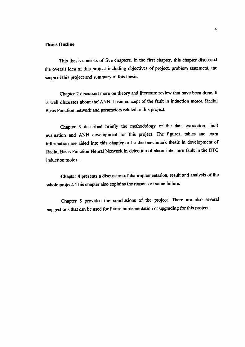
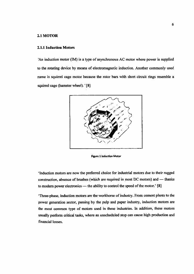
2.1.1 Induction Motors
'An induction motor (IM) is a type of asynchronous AC motor where power is supplied
to the rotating device by means of electromagnetic induction. Another commonly used
flame is squirrel cage motor because the rotor bars with short circuit rings resemble a
squirrel cage (hamster wheel). '[8]
5>
I / /
Figure 1 induction Motor
'Induction motors are now the preferred choice for industrial motors due to their rugged
construction, absence of brushes (which are required in most DC motors) and - thanks
to modem power electronics - the ability to control the speed of the motor.' [8]
'Three-phase, induction motors are the workhorse of industry. From cement plants to the
power generation sector, passing by the pulp and paper industry, induction motors are
the most common type of motors used in these industries. In addition, these motors
usually perform critical tasks, where an unscheduled stop can cause high production and
financial losses.
7
Statistical studies have demonstrated that common types of faults in three-phase
induction motors are roll bearings damage, stator faults, both in the electric and
magnetic circuit, air gap eccentricity, and rotor faults such as broken rotor bars.
Therefore, a lot of works have been done in the last two decades for the development of
adequate diagnostic techniques, able to detect these faults as soon as possible, in order to
prevent major damages to the machine s thus decreasing downtime and the repair cost.
Although most of the diagnostic techniques were initially developed for line-connected
motors, the high penetration rates of induction motor drives, particularly those drive
systems based on vector controlled and direct torque controlled induction motors, have
created new challenges and established new targets for the diagnostic system. The high
harmonic content introduced in the current and voltage signals, as well as the existence
of closed loops in the control system of these drives make the diagnostic process more
complicated than ever. In these adverse conditions, most of the traditional diagnostic
techniques that were effective for line-connected motors fail when dealing with
induction motor drives. Other aspect that should be emphasized at this point is the use of
different diagnostic techniques to diagnose different types of faults, as it appears that no
technique is able to cope easily with all types of faults. Moreover, some of the diagnostic
techniques proposed so far rely on a detailed knowledge about the motor, usually
difficult to obtain when the motors are already installed and in operation'.[9]
8
2.2 CONTROLLER
2.2.1 Direct Torque Control (DTC)
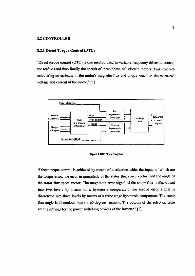
'Direct torque control (DTC) is one method used in variable frequency drives to control
the torque (and thus finally the speed) of three-phase AC electric motors. This involves
calculating an estimate of the motor's magnetic flux and torque based on the measured
voltage and current of the motor.' [6]
Flux reference -
Flux
Phase Flux hysteresis
currents Flux Flux sectorcontroller Look-up TiansStt
and torque Tors table control
TorqueP
^ 24
signals
Phase estimation
voltages
Torque reference - - - -- -
Figure 2 DTC Block Diagram
'Direct torque control is achieved by means of a selection table, the inputs of which are
the torque error, the error in magnitude of the stator flux space vector, and the angle of
the stator flux space vector. The magnitude error signal of the stator flux is discretized
into two levels by means of a hysteresis comparator. The torque error signal is
discretized into three levels by means of a three stage hysteresis comparator. The stator
flux angle is discretized into six 60 degrees sections. The outputs of the selection table
are the settings for the power switching devices of the inverter.' [2]
9
'Controllers based on direct torque control do not require a complex coordinate
transform. The decoupling of the nonlinear ac motor structure is obtained by the use of
on-off control, which can be related to the on-off operation of the inverter power
switches. Similarly to field oriented control, the flux and the torque are either measured
or estimated and used as feedback signals for the controller. However, as opposed to
field oriented controls the states of the power switches are determined directly from the
measured and the reference torque and flux signals' [2]
10
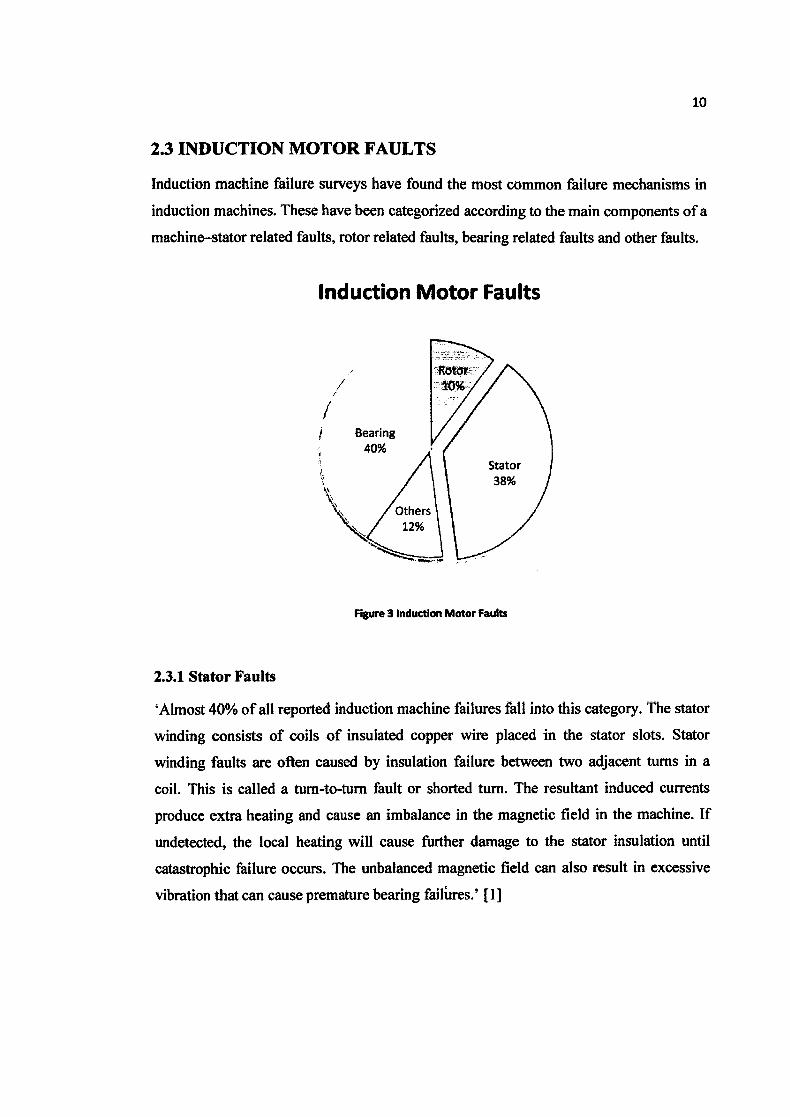
2.3 INDUCTION MOTOR FAULTS
Induction machine failure surveys have found the most common failure mechanisms in
induction machines. These have been categorized according to the main components of a
machine—stator related faults, rotor related faults, bearing related faults and other faults.
Induction Motor Faults
Bearing
/
Others 12%
Figure 3 Induction Motor Faults
2.3.1 Stator Faults
'Almost 40% of all reported induction machine failures fall into this category. The stator
winding consists of coils of insulated copper wire placed in the stator slots. Stator
winding faults are often caused by insulation failure between two adjacent turns in a
coil. This is called a turn-to-turn fault or shorted turn. The resultant induced currents
produce extra heating and cause an imbalance in the magnetic field in the machine. If
undetected, the local heating will cause further damage to the stator insulation until
catastrophic failure occurs. The unbalanced magnetic field can also result in excessive
vibration that can cause premature bearing failures.' [1]

Some of the most frequent causes of stator winding failures are:
• high stator core or winding temperatures,
• slack core lamination, slot wedges, and joints,
• loose bracing for end winding,
• contamination caused by oil, moisture, and dirt,
• short circuits,
• starting stresses,
• electrical discharges,
• leakage in the cooling systems
11
12
2.4 SENSOR SIGNALS
As the induction machine is highly symmetrical, the presence of any kind of fault in it
affects its symmetry. This leads to a corresponding change in the interaction of flux
between the stator and rotor, resulting in changes to the stator currents, voltages,
magnetic field and machine vibration. Thus these signals can be used for on-line
condition monitoring.
2.4.1 Vibration
Vibration monitoring is one of the oldest condition monitoring techniques and is widely
used to detect mechanical faults such as bearing failures or mechanical imbalance. A
piezo-electric transducer providing a voltage signal proportional to acceleration is often
used. This acceleration signal can be integrated to give the velocity or position.
2.4.2 Stator Current
The stator current is usually measured using a clip-on Hall-effect current probe. It
contains frequency components which can be related to a variety of faults such as
mechanical and magnetic asymmetries, broken rotor bars and shorted turns in the stator
windings. Most of the published research work in recent years has examined the use of
the stator current for condition monitoring, particularly using frequency analysis.
2.4.3 Axial Magnetic Flux
The axial magnetic leakage flux of an induction machine is readily measured using a
circular search coil which is placed on the nondrive (rear) end of the machine,
concentric with the shaft. The search coil produces an output voltage which is
proportional to the rate of change of the axial leakage flux. This signal contains many of
the same frequency components which are present in the stator current. It is particularly
useful for estimating the speed as it contains a strong component at the slip frequency.
13
2.4.4 Stator Voltage
This can be safely measured using a high frequency differential voltage probe or
isolation amplifier. It has been used to calculate the instantaneous power, instantaneous
torque and negative sequence impedance.
2.4.5 Other Techniques
Temperature sensors monitoring the bearings and stator windings have been traditionally
used for condition monitoring. They provide a useful indication of machine overheating
but offer limited fault diagnostic capability.
Partial discharge analysis is used for detecting stator insulation faults in higher voltage
motors. It consists of detecting the low amplitude, ultrafast pulses (nS) produced by
electric discharges in small voids in the insulation. Partial discharges occur even in
healthy machines, however an increase in the amount of partial discharge activity can be
associated with insulation degradation.

14
2.5 SIGNAL PROCESSING TECIINIQIJTE
Signal processing techniques are applied to the measured sensor signals in order to
generate features or parameters (e.g. amplitudes of frequency components associated
with faults) which are sensitive to the presence or absence of specific faults.
2.5.1 RMS
'Calculation of simple statistical parameters such as the overall root mean squared
(RMS) value of a signal can give useful information. For instance, the RMS value of the
vibration velocity is a convenient measure of the overall vibration severity. In the same
way, the RMS value of the stator current provides a rough indication of the motor
loading.'
2.5.2 Frequency Analysis
'Frequency analysis using the Fourier transform is the most common signal processing
method used for online condition monitoring. This is because many mechanical and
electrical faults produce signals whose frequencies can be determined from knowledge
of motor parameters such as the number of poles. These fault signals appear in a variety
of sensor signals including vibration, current and flux.' [1]
'The supplied current waveform and the phase current waveform are not sinusoid so that
the frequency spectrum of the current is abundant. With the different control strategies,
the current waveform and the harmonic component are different. Un-sinusoid waveform
current could cause the electromagnetic interference.
2.4.3 Other Frequency Analysis Methods
The Fourier transform used for conventional frequency analysis assumes that the
frequency spectrum is not changing with respect to time over the sampling period. This
assumption is not always valid, especially with mechanical loads which show
considerable variation over time.
Time-frequency techniques overcome this issue by Current Spectrum (dB) dividing the
signal into short time segments over which it is relatively constant, and computing the