Embed Size (px)
Citation preview

EE152 Green Electronics
Power Circuits Photovoltaics
9/30/15
Prof. William Dally Computer Systems Laboratory
Stanford University
Course Logistics • HW2 out Today due Monday 10/5 • Lab1 signed off this week • Lab2 out
EE155/255 Lecture 3 - Power Devices
Course to Date • We need sustainable energy systems • At the core they are voltage converters • Periodic steady-state analysis, buck and boost • Intelligent control + power path • Intelligent control done with event-driven embedded
software • Real devices have switching and conduction loss
EE155/255 Lecture 3 - Power Devices

Snubbers
EE155/255 Lecture 3 - Power Devices

LD
G 50V
+-
40A
RS
CS
D
Cj
M
Dampen Ringing Nodes
LD and Cj resonate when M is on Parallel RS dampens tank Series CS limits dissipation
EE155/255 Lecture 3 - Power Devices
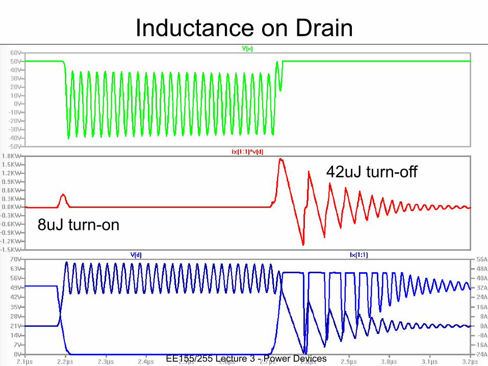
Inductance on Drain
8uJ turn-on
42uJ turn-off
EE155/255 Lecture 3 - Power Devices

With Snubber (1nF, 5Ω)
8uJ turn-on
2uJ in snubber
42uJ turn-off
EE155/255 Lecture 3 - Power Devices

LD
G 50V
+-
40A
RS
CS
D
Cj
M
Design Procedure
Pick RS ~ 1/ωCj Pick CS so
τ >= π/ωOr
Es = CSV2/2
EE155/255 Lecture 3 - Power Devices

G 50V+-
40A
RS
CS
D
M
DS
Move Turn-Off Dissipation to Passive Device
CS slows rise time of drain
CSV2/2RS dissipated in RS when CS discharges
Rarely used today
Other forms slow fall time and rising/falling current EE155/255 Lecture 3 - Power Devices

Lab Half-Bridge Module
EE155/255 Lecture 3 - Power Devices
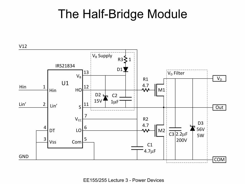
The Half-Bridge Module
1
2
Hin
IRS21834
ComVss
LO
S
HO
COM
Out
VDVB
M1
M2
R14.7
R24.7
U1
����
VCC
3
DT
GND
4
Hin
����
V12
C14.7 F
2.2 F200V
D356V5W
D1
R3 1
C21 F
VBCSupply
VDCFilter
D215V
C3
7
6
5
13
12
11
EE155/255 Lecture 3 - Power Devices
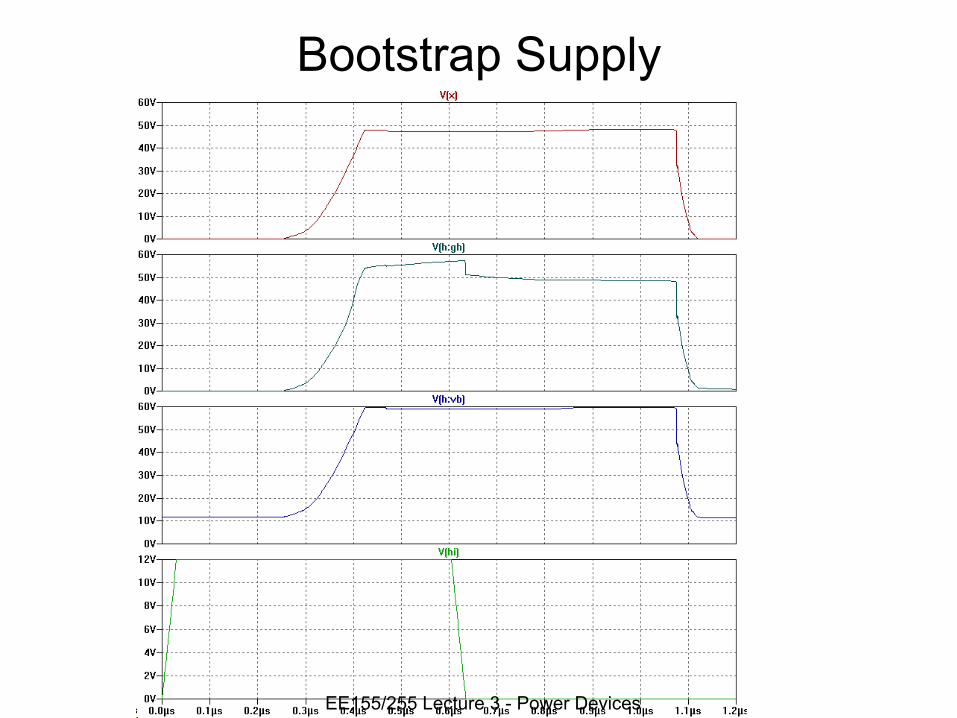
Bootstrap Supply
EE155/255 Lecture 3 - Power Devices
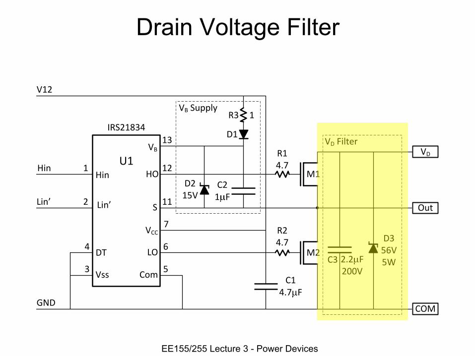
Drain Voltage Filter
1
2
Hin
IRS21834
ComVss
LO
S
HO
COM
Out
VDVB
M1
M2
R14.7
R24.7
U1
����
VCC
3
DT
GND
4
Hin
����
V12
C14.7 F
2.2 F200V
D356V5W
D1
R3 1
C21 F
VBCSupply
VDCFilter
D215V
C3
7
6
5
13
12
11
EE155/255 Lecture 3 - Power Devices

Drain Voltage Filter 300nH Input Inductance
EE155/255 Lecture 3 - Power Devices

SPICE
EE155/255 Lecture 3 - Power Devices

SPICE Example – A Voltage Doubler
EE155/255 Lecture 3 - Power Devices

A Voltage Doubler * Simple voltage "doubler".include "gel.lib".param td=100n tr=100n tf=100n tw=2.5u tcy=5u ncy=2.param l1=22uH c1=10uF r1=10
* call half-bridge subcircuitxhb vd mid g g 0 v12 gel_hb
* circuitl1 vin mid {l1}c1 vd 0 {c1}r1 vd 0 {r1}
* suppliesv12 v12 0 12vin vin 0 24
* stimulusVG g 0 PULSE(0 5 {td} {tr} {tf} {tw} {tcy} {ncy})
.ic i(l1)=9.2
.ic v(vd)=42.8
.tran {ncy*tcy}
EE155/255 Lecture 3 - Power Devices

Turn-On Transient
EE155/255 Lecture 3 - Power Devices
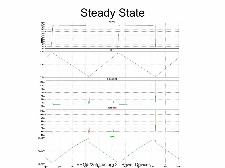
Steady State
EE155/255 Lecture 3 - Power Devices
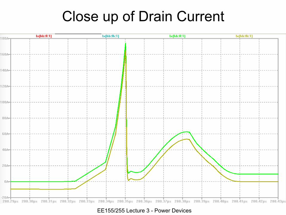
Close up of Drain Current
EE155/255 Lecture 3 - Power Devices
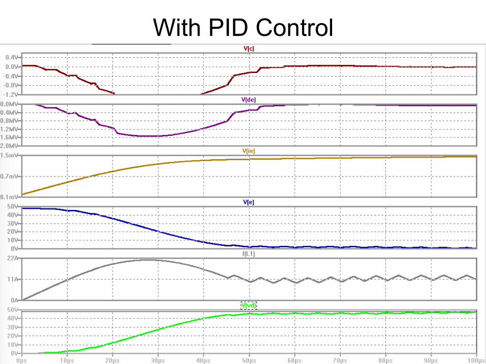
With PID Control
EE155/255 Lecture 3 - Power Devices
A Warning • SPICE (or any simulator) is a Verification tool, not a Design tool
• Design your circuit first – Use Excel, Matlab, a calculator etc… to calculate component
values • Then simulate your circuit to check operation and fine-
tune parameters • Don’t try to design your circuit using SPICE
• Simulation is not a substitute for thinking
EE155/255 Lecture 3 - Power Devices
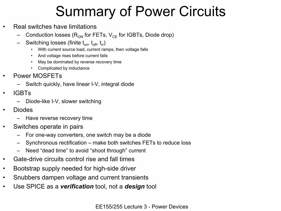
Summary of Power Circuits • Real switches have limitations
– Conduction losses (RON for FETs, VCE for IGBTs, Diode drop) – Switching losses (finite ton, toff, trr)
• With current source load, current ramps, then voltage falls • And voltage rises before current falls • May be dominated by reverse recovery time • Complicated by inductance
• Power MOSFETs – Switch quickly, have linear I-V, integral diode
• IGBTs – Diode-like I-V, slower switching
• Diodes – Have reverse recovery time
• Switches operate in pairs – For one-way converters, one switch may be a diode – Synchronous rectification – make both switches FETs to reduce loss – Need “dead time” to avoid “shoot through” current
• Gate-drive circuits control rise and fall times • Bootstrap supply needed for high-side driver • Snubbers dampen voltage and current transients • Use SPICE as a verification tool, not a design tool
EE155/255 Lecture 3 - Power Devices

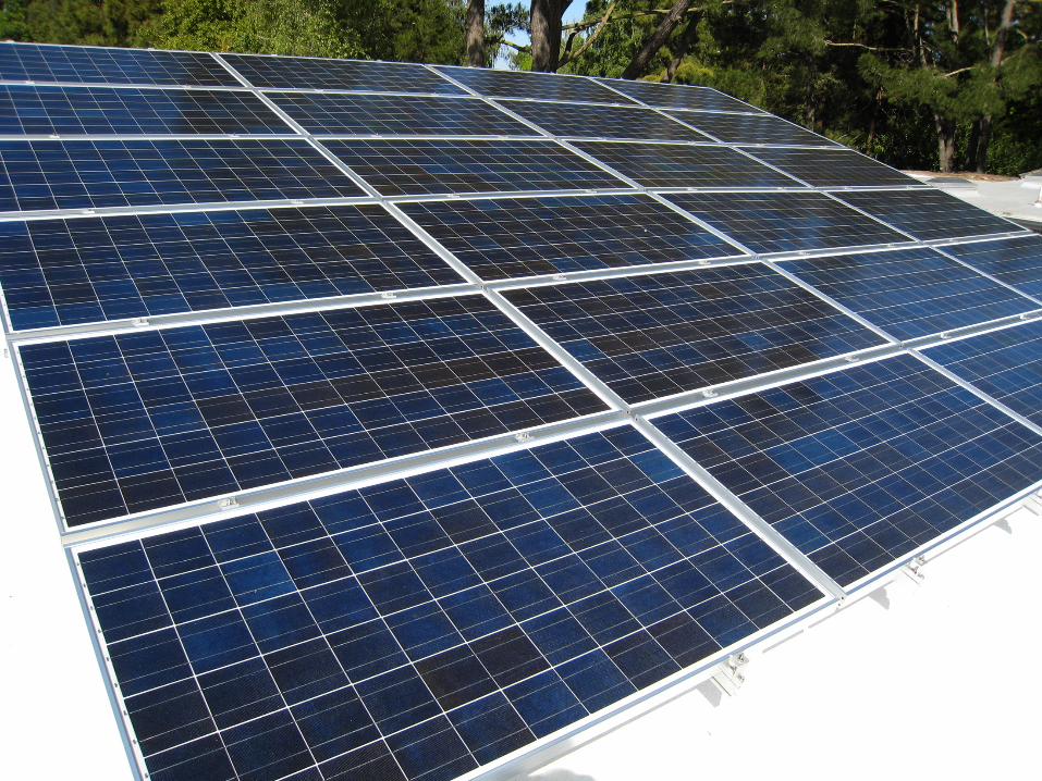
Photovoltaics
EE155/255 Lecture 3 - Power Devices
Energy Conversion
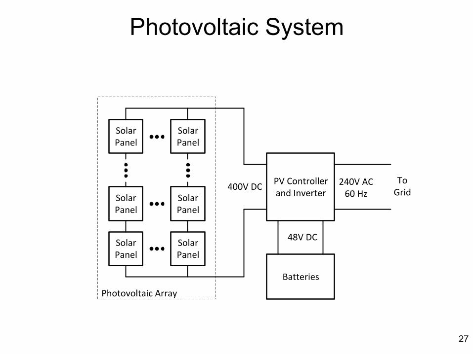
Photovoltaic System
Solar Panel
Solar Panel
Solar Panel
Solar Panel
Solar Panel
Solar Panel
Photovoltaic Array
PV Controller and Inverter
Batteries
400V DC 240V AC60 Hz
48V DC
To Grid
27

28
M
215 Installation and Operation
C
opyright � 2012 Enphase Energy
141-00012 Rev 04
29
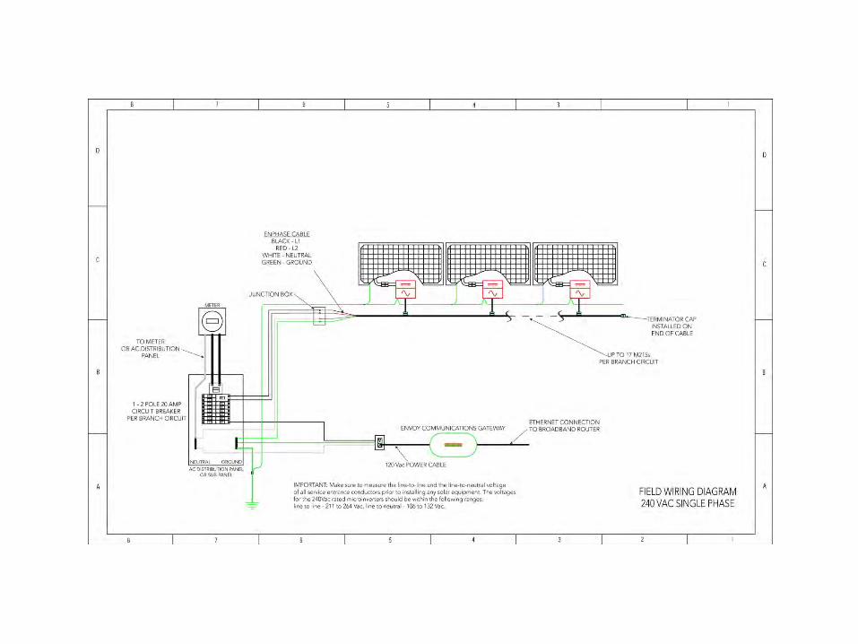
Sam
ple Wiring D
iagram – M
215, 240 VA
C
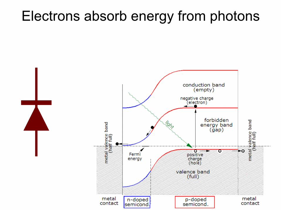
Electrons absorb energy from photons
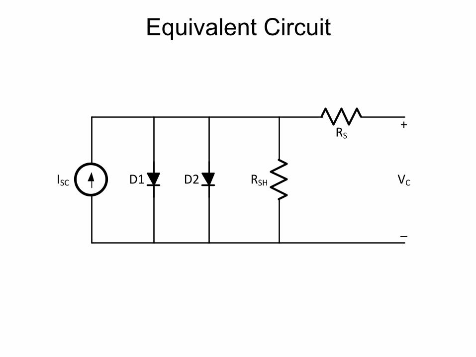
Equivalent Circuit
RSHISC
RS
D1 VC
+
_
D2
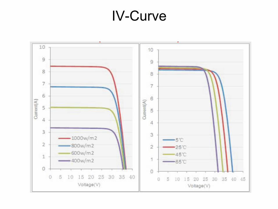
IV-Curve

Typical Module CS6P 60 cells in series ~0.5V per cell 3 strings of 20 with bypass diode on each string
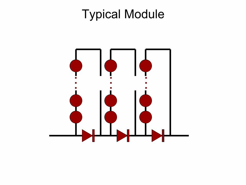
Typical Module
… … …

IV Curve from SPICE Model

Peak-Power Tracking • Find point on IV curve where power is maximized.
Start at any point (v(0),i(0)) “Dither” v, v(i+1) = v(i) + Δv Check result: if(p(i+1) < p(i)) v(i+1) = v(i) Try both directions: Δv = -Δv
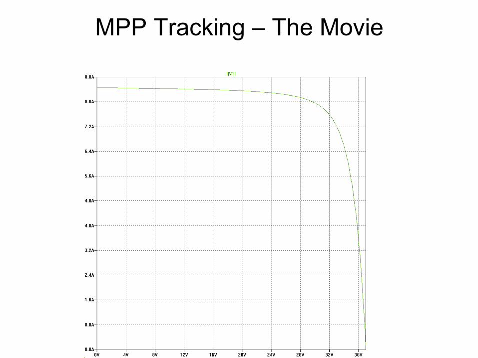
MPP Tracking – The Movie

Start at (35 V, 5.5A) P=192.5

Dither by DV = 0.5V to V = 35.5V (35.5V, 4.7A) P=166.9 < 192.5
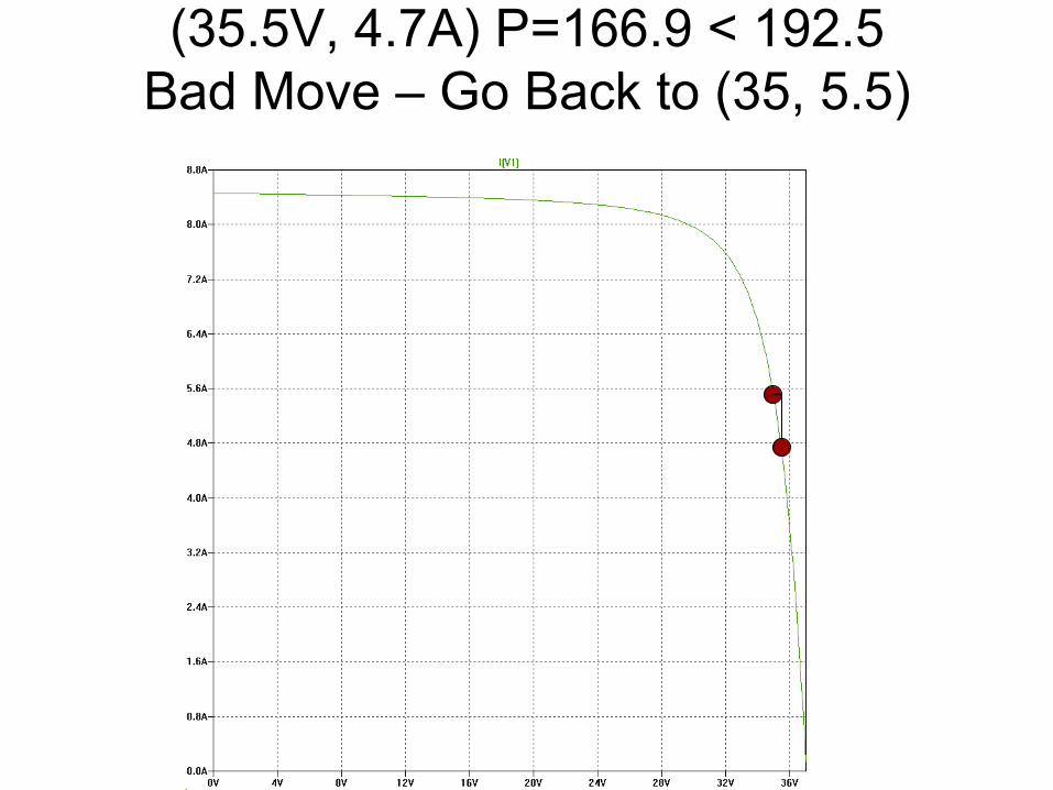
(35.5V, 4.7A) P=166.9 < 192.5 Bad Move – Go Back to (35, 5.5)
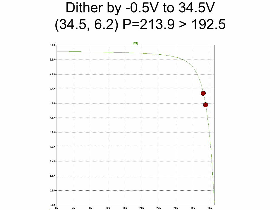
Dither by -0.5V to 34.5V (34.5, 6.2) P=213.9 > 192.5

(34.5, 6.2) P=213.9 > 192.5 Keep move and keep going
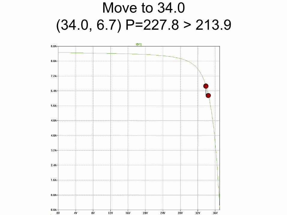
Move to 34.0 (34.0, 6.7) P=227.8 > 213.9

(34.0, 6.7) P=227.8 > 213.9 Keep move and keep going
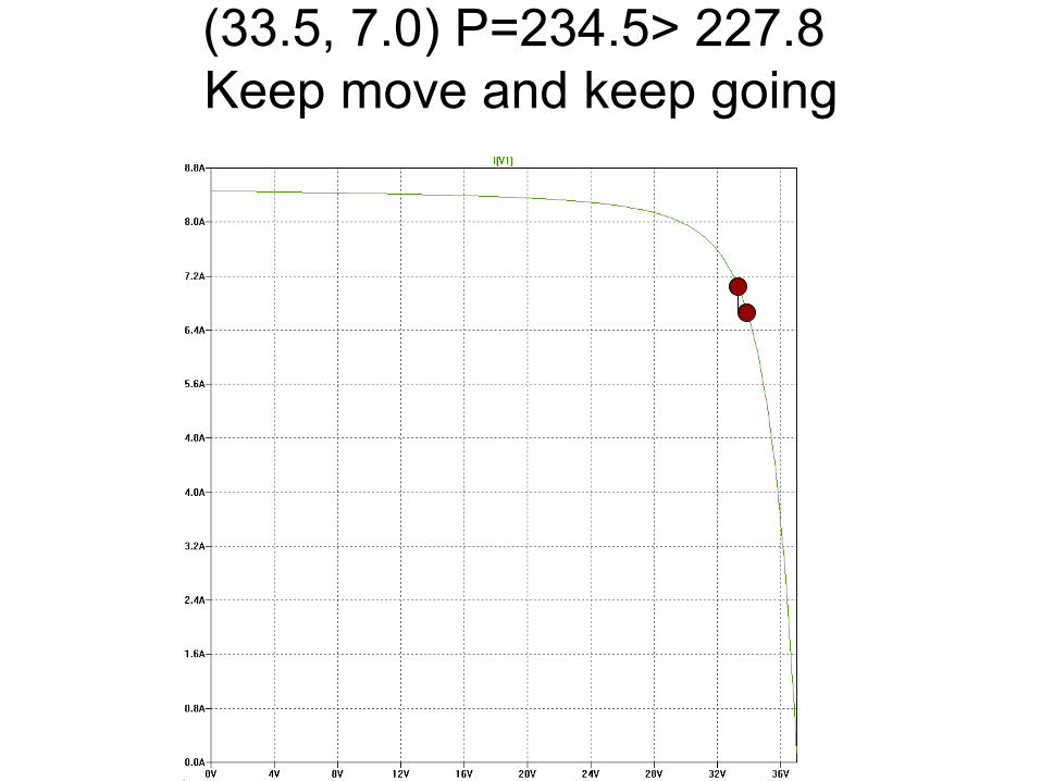
(33.5, 7.0) P=234.5> 227.8 Keep move and keep going
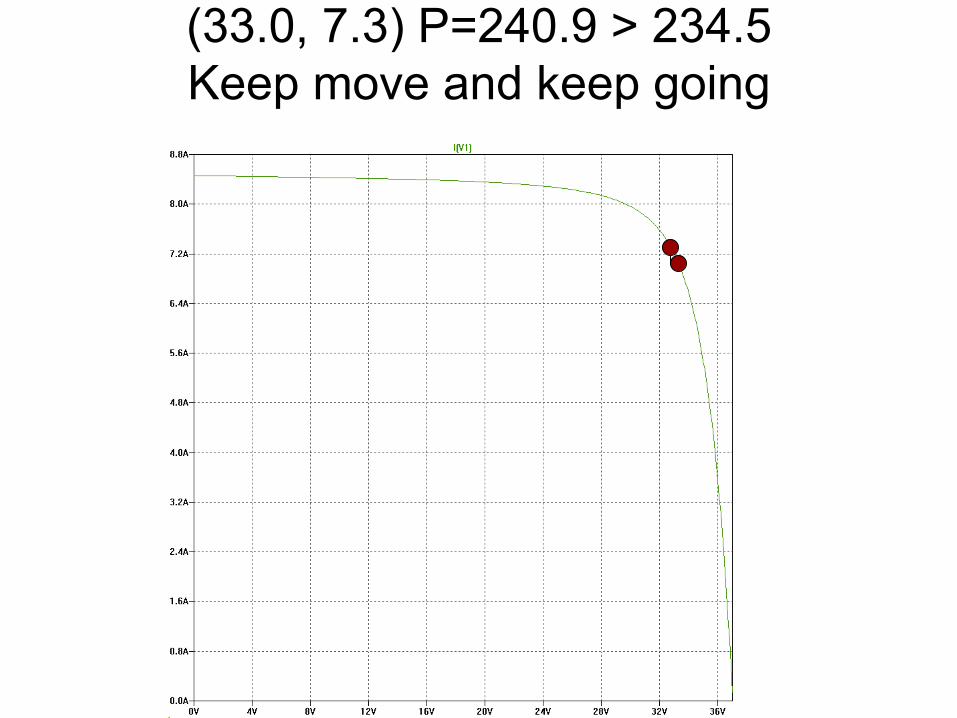
(33.0, 7.3) P=240.9 > 234.5 Keep move and keep going

(32.5, 7.5) P=243.75 > 240.9 Keep move and keep going
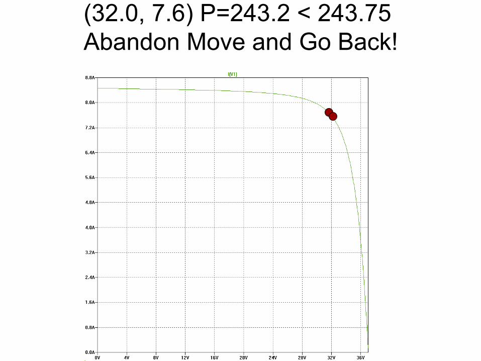
(32.0, 7.6) P=243.2 < 243.75 Abandon Move and Go Back!
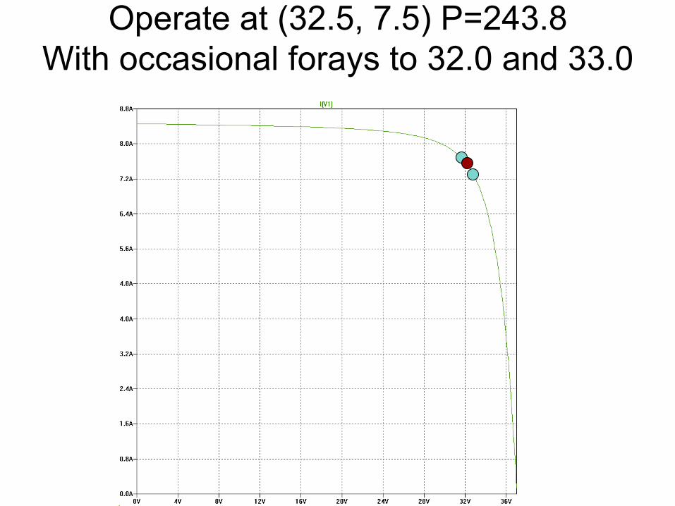
Operate at (32.5, 7.5) P=243.8 With occasional forays to 32.0 and 33.0

“Hillclimbing” On the Power Curve

Compound Power Curve

Compound Power Curve (2 Panels)
Not convex How do you find maximum power point?
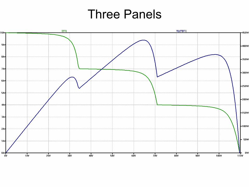
Three Panels
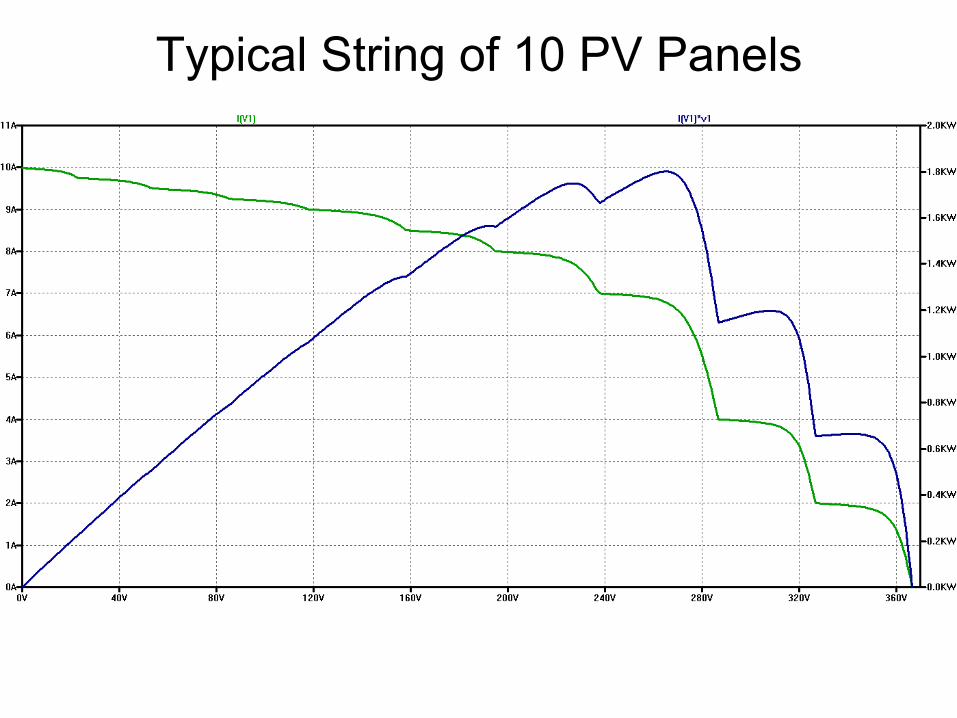
Typical String of 10 PV Panels
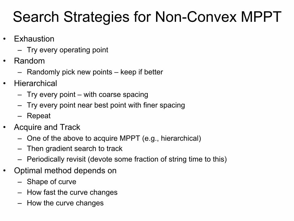
Search Strategies for Non-Convex MPPT • Exhaustion
– Try every operating point • Random
– Randomly pick new points – keep if better • Hierarchical
– Try every point – with coarse spacing – Try every point near best point with finer spacing – Repeat
• Acquire and Track – One of the above to acquire MPPT (e.g., hierarchical) – Then gradient search to track – Periodically revisit (devote some fraction of string time to this)
• Optimal method depends on – Shape of curve – How fast the curve changes – How the curve changes
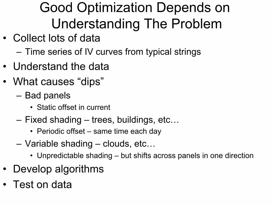
Good Optimization Depends on Understanding The Problem
• Collect lots of data – Time series of IV curves from typical strings
• Understand the data • What causes “dips”
– Bad panels • Static offset in current
– Fixed shading – trees, buildings, etc… • Periodic offset – same time each day
– Variable shading – clouds, etc… • Unpredictable shading – but shifts across panels in one direction
• Develop algorithms • Test on data

An Example of Optimization • Trade-off parameters against one another to maximize
a figure of merit.
• In this case, parameters are panel voltage and current.
• Figure of merit is power.
• Optimization is done real-time because temperature and irradiance change. – Sometimes optimization is done at design time, or calibration
time.

MPPT Power Path (Boost Converter with Energy Meter)
Ci
VPV
PV Panel
RS
M1G
CO
L1
Load
M2G
VL
IPV
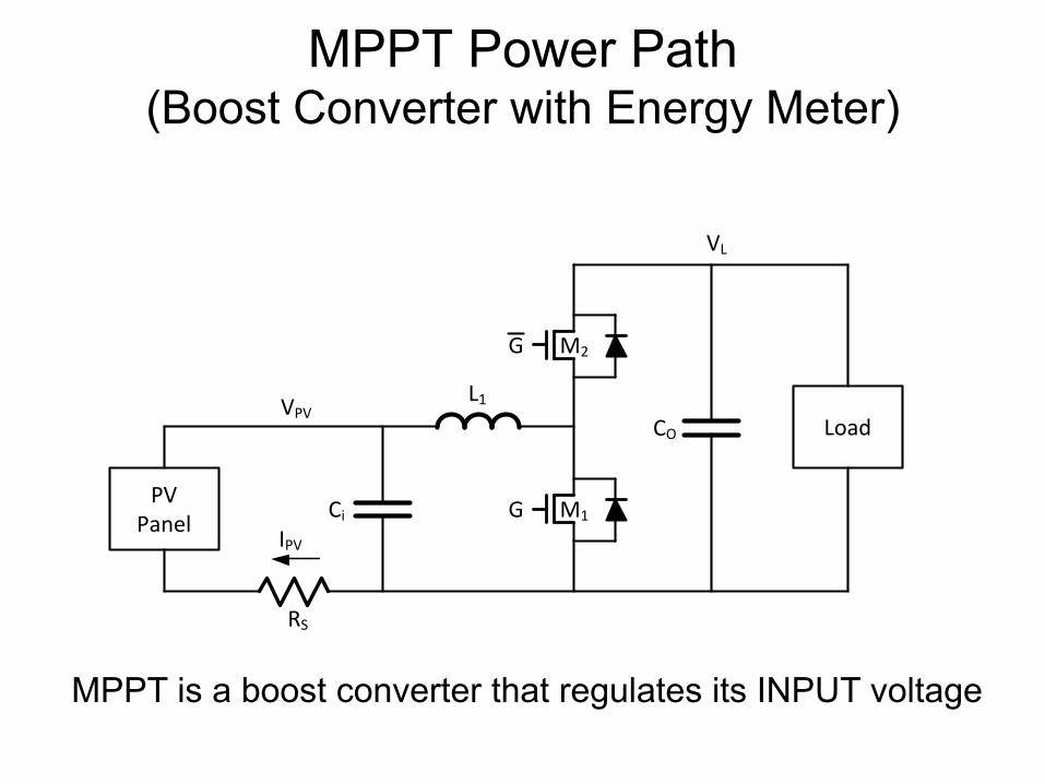
MPPT Power Path (Boost Converter with Energy Meter)
Ci
VPV
PV Panel
RS
M1G
CO
L1
Load
M2G
VL
IPV
MPPT is a boost converter that regulates its INPUT voltage
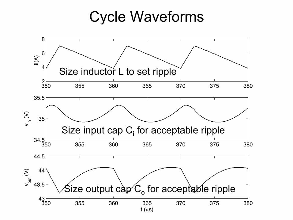
Cycle Waveforms
350 355 360 365 370 375 3802
4
6
8il(
A)
350 355 360 365 370 375 38034.5
35
35.5
v in (V
)
350 355 360 365 370 375 38043
43.5
44
44.5
v out (V
)
t (µs)
Size input cap Ci for acceptable ripple
Size output cap Co for acceptable ripple
Size inductor L to set ripple
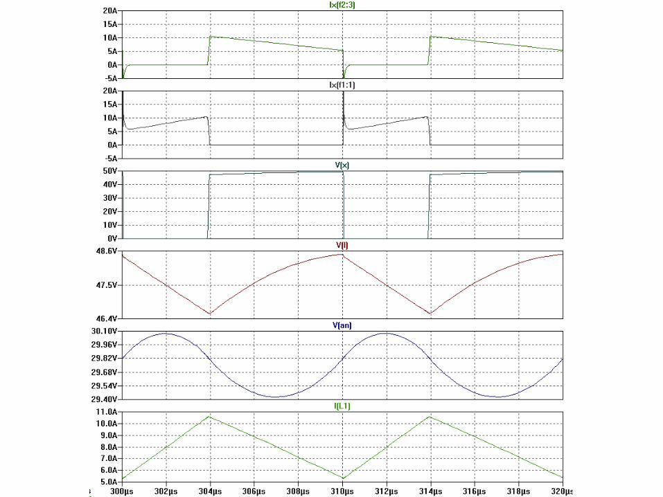
SPICE

Longer Simulation
0 2 4 6 8 10 12 14 1610
20
30
40
v in(V
)
0 2 4 6 8 10 12 14 160
5
10i pv
(A)
0 2 4 6 8 10 12 14 1620
40
60
v out(V
)
0 2 4 6 8 10 12 14 160
0.2
0.4
D
0 2 4 6 8 10 12 14 1650
100150200250
P (W
)
t (ms)

PV Systems

Microinverter
Panel Inverter AC Line 240 Vrms ~1Arms
30-40V 0-10A
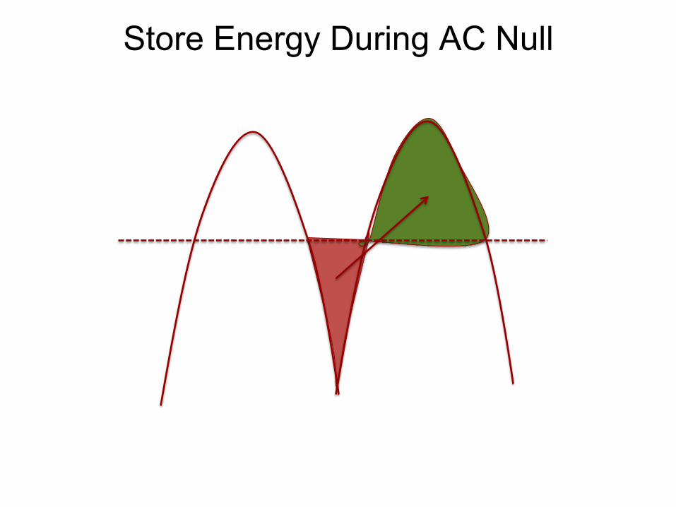
Store Energy During AC Null

Approach 1 – DC Link
Boost
30-40V 0-10A
340-600V 0-1A
Buck Unfold
Rectified AC 240V, 1A rms

Approach 2 – Single Stage
30-40V 0-10A
Convert Unfold
Rectified AC 240V, 1A rms
Buck
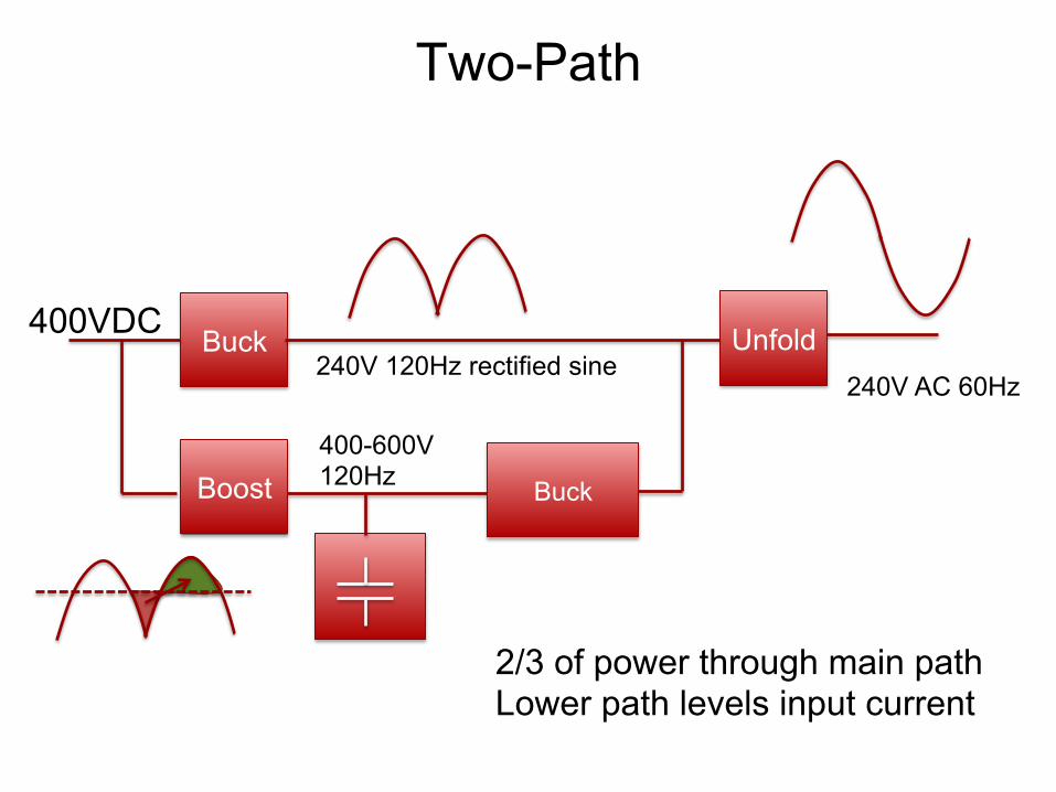
Boost
400VDC Unfold
400-600V 120Hz Buck
240V 120Hz rectified sine 240V AC 60Hz
2/3 of power through main path Lower path levels input current
Two-Path
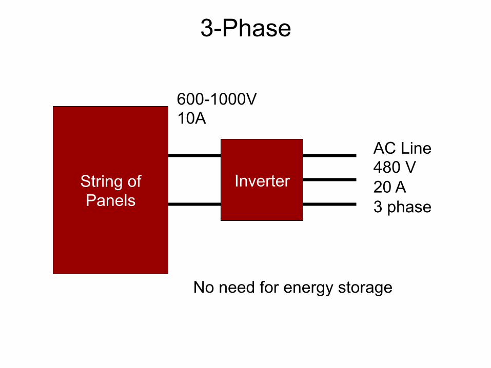
3-Phase
String of Panels
Inverter
AC Line 480 V 20 A 3 phase
600-1000V 10A
No need for energy storage

48V34AH
RCSF1
C1
A
A
B
B
C
C
A B C
3-Φ Inverter Power Path

Transformerless
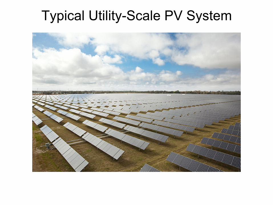
Typical Utility-Scale PV System
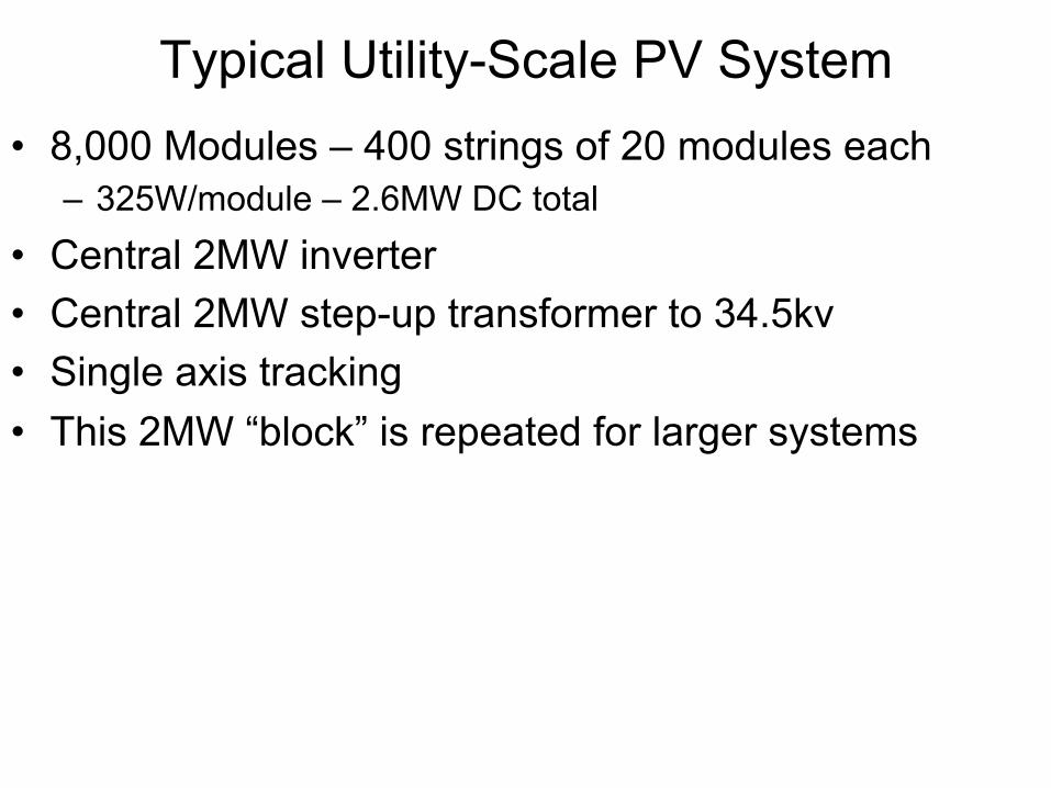
Typical Utility-Scale PV System • 8,000 Modules – 400 strings of 20 modules each
– 325W/module – 2.6MW DC total
• Central 2MW inverter • Central 2MW step-up transformer to 34.5kv • Single axis tracking • This 2MW “block” is repeated for larger systems
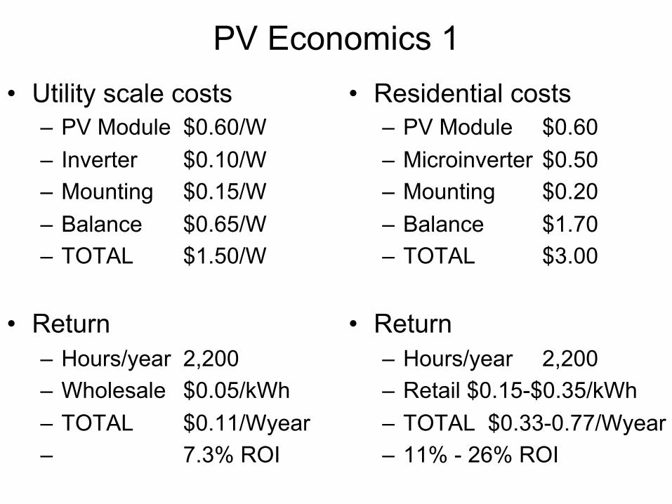
PV Economics 1 • Utility scale costs
– PV Module $0.60/W – Inverter $0.10/W – Mounting $0.15/W – Balance $0.65/W – TOTAL $1.50/W
• Return – Hours/year 2,200 – Wholesale $0.05/kWh – TOTAL $0.11/Wyear – 7.3% ROI
• Residential costs – PV Module $0.60 – Microinverter $0.50 – Mounting $0.20 – Balance $1.70 – TOTAL $3.00
• Return – Hours/year 2,200 – Retail $0.15-$0.35/kWh – TOTAL $0.33-0.77/Wyear – 11% - 26% ROI

PV Economics 2 • Module is only 40% of cost (20% for residential) • Real issue is balance-of-system (installation labor)
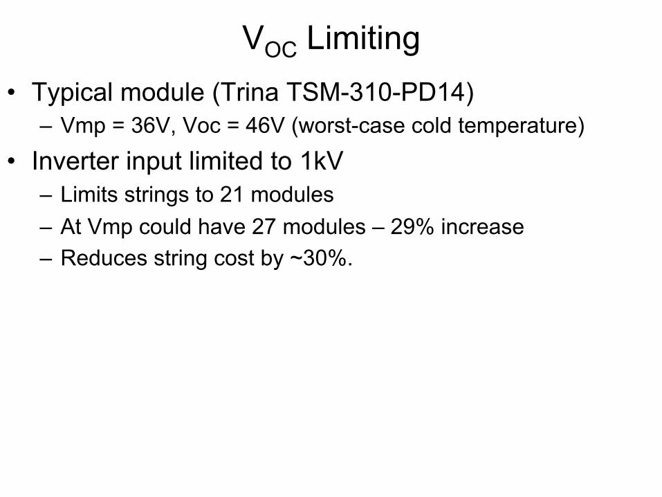
VOC Limiting • Typical module (Trina TSM-310-PD14)
– Vmp = 36V, Voc = 46V (worst-case cold temperature)
• Inverter input limited to 1kV – Limits strings to 21 modules – At Vmp could have 27 modules – 29% increase – Reduces string cost by ~30%.
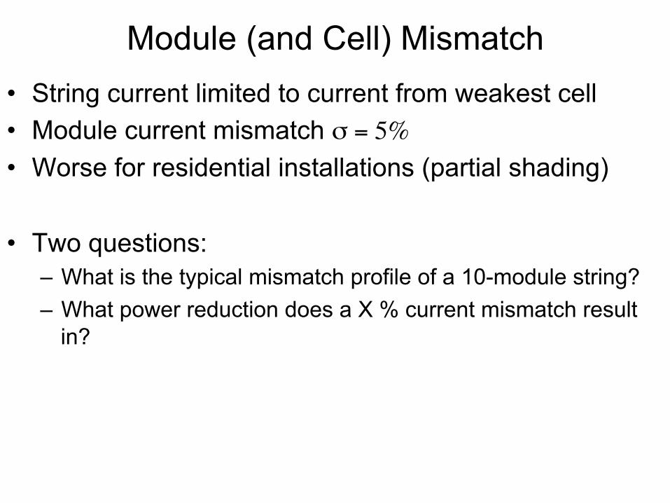
Module (and Cell) Mismatch • String current limited to current from weakest cell • Module current mismatch σ = 5%
• Worse for residential installations (partial shading)
• Two questions: – What is the typical mismatch profile of a 10-module string? – What power reduction does a X % current mismatch result
in?

Faults and Failures • Cell open/short • Diode open/short • Arc fault
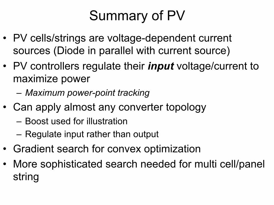
Summary of PV • PV cells/strings are voltage-dependent current
sources (Diode in parallel with current source) • PV controllers regulate their input voltage/current to
maximize power – Maximum power-point tracking
• Can apply almost any converter topology – Boost used for illustration – Regulate input rather than output
• Gradient search for convex optimization • More sophisticated search needed for multi cell/panel
string
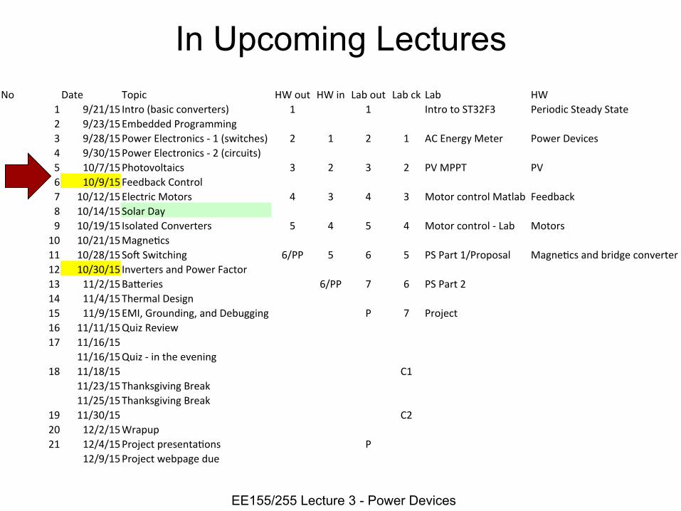
In Upcoming Lectures
EE155/255 Lecture 3 - Power Devices
No Date Topic HW out HW in Lab out Lab ck Lab HW 1 9/21/15 Intro (basic converters) 1 1 Intro to ST32F3 Periodic Steady State 2 9/23/15 Embedded Programming 3 9/28/15 Power Electronics -‐ 1 (switches) 2 1 2 1 AC Energy Meter Power Devices 4 9/30/15 Power Electronics -‐ 2 (circuits) 5 10/7/15 Photovoltaics 3 2 3 2 PV MPPT PV 6 10/9/15 Feedback Control 7 10/12/15 Electric Motors 4 3 4 3 Motor control Matlab Feedback 8 10/14/15 Solar Day 9 10/19/15 Isolated Converters 5 4 5 4 Motor control -‐ Lab Motors 10 10/21/15 MagneTcs 11 10/28/15 SoU Switching 6/PP 5 6 5 PS Part 1/Proposal MagneTcs and bridge converter 12 10/30/15 Inverters and Power Factor 13 11/2/15 BaWeries 6/PP 7 6 PS Part 2 14 11/4/15 Thermal Design 15 11/9/15 EMI, Grounding, and Debugging P 7 Project 16 11/11/15 Quiz Review 17 11/16/15
11/16/15 Quiz -‐ in the evening 18 11/18/15 C1
11/23/15 Thanksgiving Break 11/25/15 Thanksgiving Break
19 11/30/15 C2 20 12/2/15 Wrapup 21 12/4/15 Project presentaTons P
12/9/15 Project webpage due