Embed Size (px)
Citation preview
EE301 - SERIES CIRCUITS, KIRCHHOFF’S VOLTAGE LAW
1 8/6/2021
Learning Objectives a. Identify elements that are connected in series b. State and apply KVL in analysis of a series circuit c. Determine the net effect of series-aiding and series-opposing voltage sources d. Compute the power dissipated by each element and the total power in a series circuit e. Explain and compute how voltage divides between elements in a series circuit f. Compute voltage drops across resistors using the voltage divider formula g. Analyze a series resistive circuit with the ground placed at various points
Series Circuits Two elements are in series if:
• They are connected at a single point (termed a node) • No other current-carrying connections exist at this node
So, in the picture on the right, 1R and 2R are in series.
Current is similar to water flowing through a pipe. Current leaving the element (e.g., a resistor) must be the same as the current entering the element.
If two elements are in series, the same current passes through them. A series circuit is constructed by connecting elements in series. The same current passes through every element of a series circuit.
Example: In each circuit below, list the resistors in series with resistor 2R .
Solution:
EE301 - SERIES CIRCUITS, KIRCHHOFF’S VOLTAGE LAW
2 8/6/2021
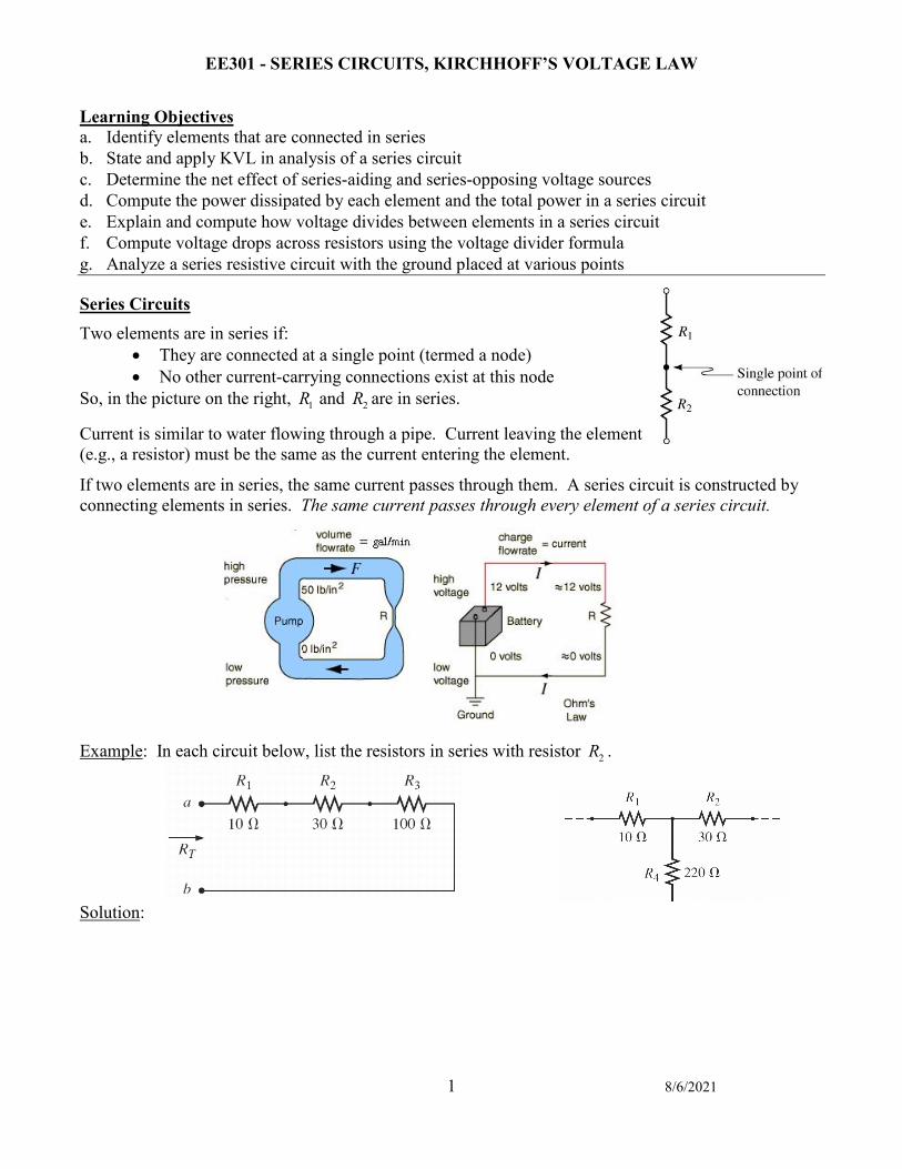
Resistors in Series Most complicated circuits can be simplified. For example, two resistors in series can be replaced by an equivalent resistance RT.
The equivalent resistance Req of any number of resistors in series is the sum of the individual resistances.
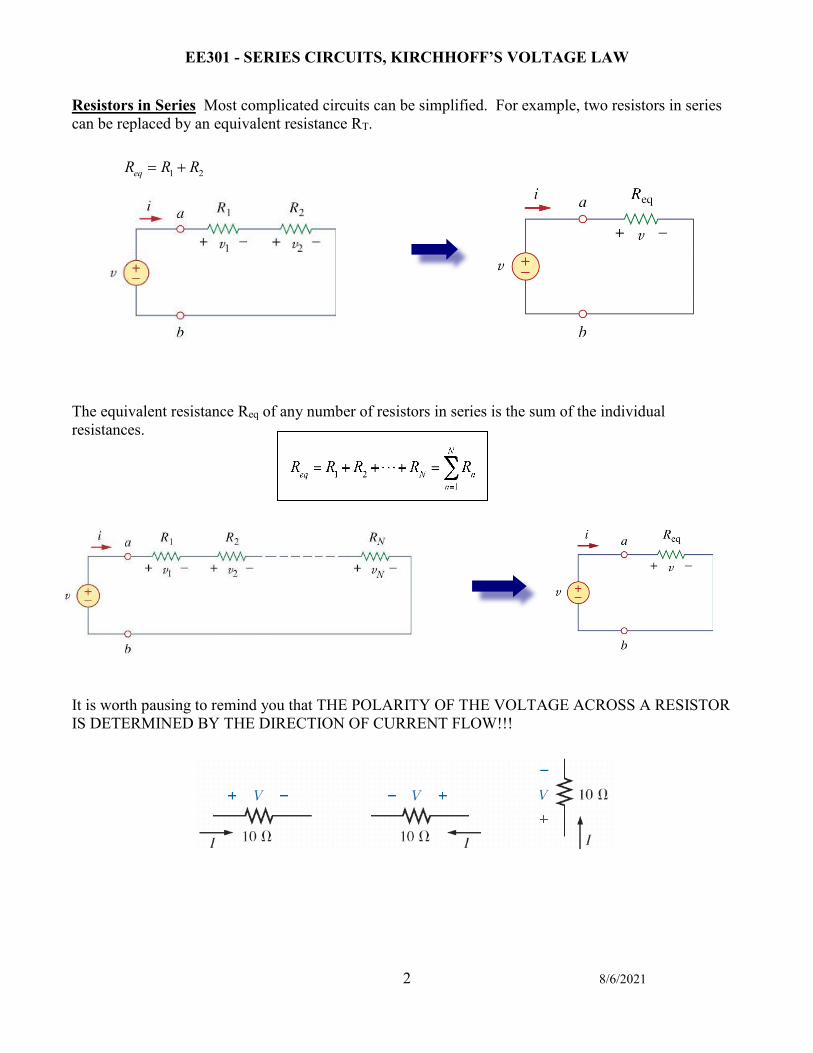
It is worth pausing to remind you that THE POLARITY OF THE VOLTAGE ACROSS A RESISTOR IS DETERMINED BY THE DIRECTION OF CURRENT FLOW!!!
1 2eqR R R= +
EE301 - SERIES CIRCUITS, KIRCHHOFF’S VOLTAGE LAW
3 8/6/2021
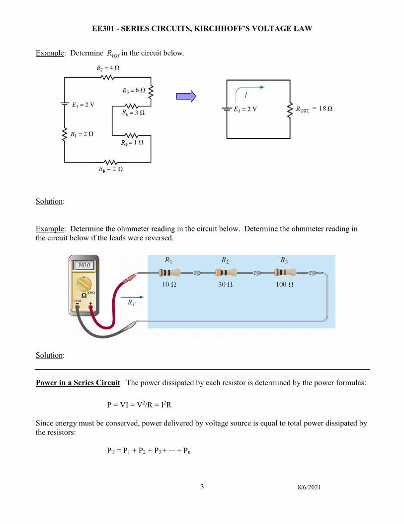
Example: Determine TOTR in the circuit below. Solution: Example: Determine the ohmmeter reading in the circuit below. Determine the ohmmeter reading in the circuit below if the leads were reversed.
Solution:
Power in a Series Circuit The power dissipated by each resistor is determined by the power formulas:
P = VI = V2/R = I2R Since energy must be conserved, power delivered by voltage source is equal to total power dissipated by the resistors: PT = P1 + P2 + P3 + ∙∙∙ + Pn
EE301 - SERIES CIRCUITS, KIRCHHOFF’S VOLTAGE LAW
4 8/6/2021
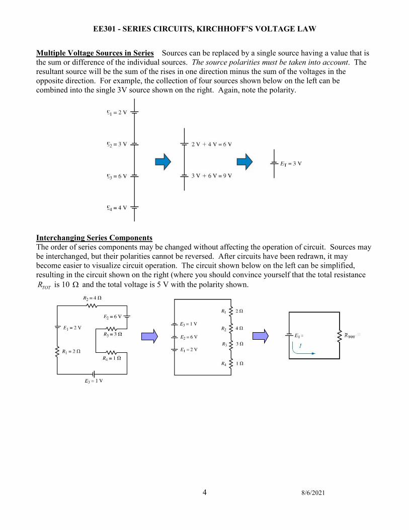
Multiple Voltage Sources in Series Sources can be replaced by a single source having a value that is the sum or difference of the individual sources. The source polarities must be taken into account. The resultant source will be the sum of the rises in one direction minus the sum of the voltages in the opposite direction. For example, the collection of four sources shown below on the left can be combined into the single 3V source shown on the right. Again, note the polarity. Interchanging Series Components The order of series components may be changed without affecting the operation of circuit. Sources may be interchanged, but their polarities cannot be reversed. After circuits have been redrawn, it may become easier to visualize circuit operation. The circuit shown below on the left can be simplified, resulting in the circuit shown on the right (where you should convince yourself that the total resistance
TOTR is 10 Ω and the total voltage is 5 V with the polarity shown.
EE301 - SERIES CIRCUITS, KIRCHHOFF’S VOLTAGE LAW
5 8/6/2021
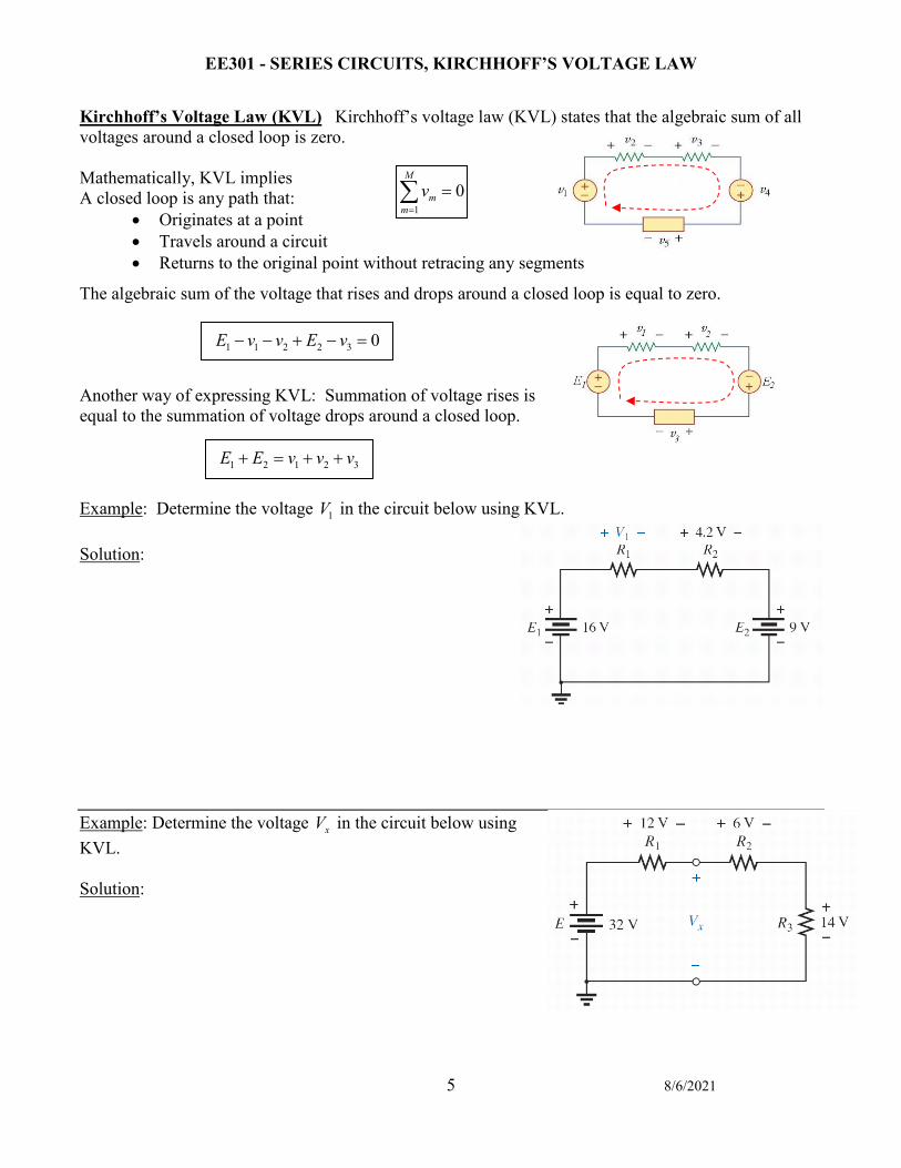
Kirchhoff’s Voltage Law (KVL) Kirchhoff’s voltage law (KVL) states that the algebraic sum of all voltages around a closed loop is zero. Mathematically, KVL implies A closed loop is any path that:
• Originates at a point • Travels around a circuit • Returns to the original point without retracing any segments
The algebraic sum of the voltage that rises and drops around a closed loop is equal to zero. Another way of expressing KVL: Summation of voltage rises is equal to the summation of voltage drops around a closed loop.
Example: Determine the voltage 1V in the circuit below using KVL.
Solution: Example: Determine the voltage xV in the circuit below using KVL.
Solution:
1 1 2 2 3 0E v v E v− − + − =
1 2 1 2 3E E v v v+ = + +
10
M
mm
v=
=∑
EE301 - SERIES CIRCUITS, KIRCHHOFF’S VOLTAGE LAW
6 8/6/2021
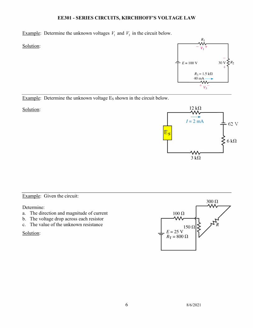
Example: Determine the unknown voltages 1V and 3V in the circuit below. Solution: Example: Determine the unknown voltage ES shown in the circuit below. Solution: Example: Given the circuit: Determine: a. The direction and magnitude of current b. The voltage drop across each resistor c. The value of the unknown resistance
Solution:

EE301 - SERIES CIRCUITS, KIRCHHOFF’S VOLTAGE LAW
7 8/6/2021
Example: Given the circuit: Determine: a. The power dissipated by each resistor and total power dissipated
by the circuit. b. Verify that the summation of the powers dissipated by the
resistors equals the total power delivered by the voltage source. Solution: Example: Given the circuit: a. Redraw the circuit with a single voltage source and single resistor. b. Determine the current.
Solution:
EE301 - SERIES CIRCUITS, KIRCHHOFF’S VOLTAGE LAW
8 8/6/2021
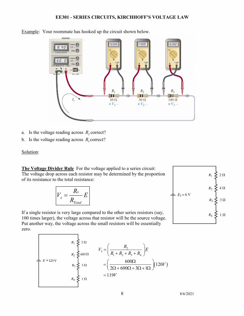
Example: Your roommate has hooked up the circuit shown below.
a. Is the voltage reading across 2R correct? b. Is the voltage reading across 3R correct? Solution: The Voltage Divider Rule For the voltage applied to a series circuit: The voltage drop across each resistor may be determined by the proportion of its resistance to the total resistance: If a single resistor is very large compared to the other series resistors (say, 100 times larger), the voltage across that resistor will be the source voltage. Put another way, the voltage across the small resistors will be essentially zero.
xx
Total
RV ER
=
( )
22
1 2 3 4
600 1202 600 3 1
119
RV ER R R R
V
V
= + + +
Ω = Ω+ Ω+ Ω+ Ω =
EE301 - SERIES CIRCUITS, KIRCHHOFF’S VOLTAGE LAW
9 8/6/2021
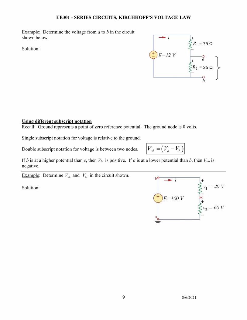
Example: Determine the voltage from a to b in the circuit shown below. Solution: Using different subscript notation Recall: Ground represents a point of zero reference potential. The ground node is 0 volts. Single subscript notation for voltage is relative to the ground. Double subscript notation for voltage is between two nodes. If b is at a higher potential than c, then Vbc is positive. If a is at a lower potential than b, then Vab is negative.
Example: Determine abV and bcV in the circuit shown. Solution:
= 75 Ω
= 25 Ω
( )ab a bV V V= −
EE301 - SERIES CIRCUITS, KIRCHHOFF’S VOLTAGE LAW
10 8/6/2021
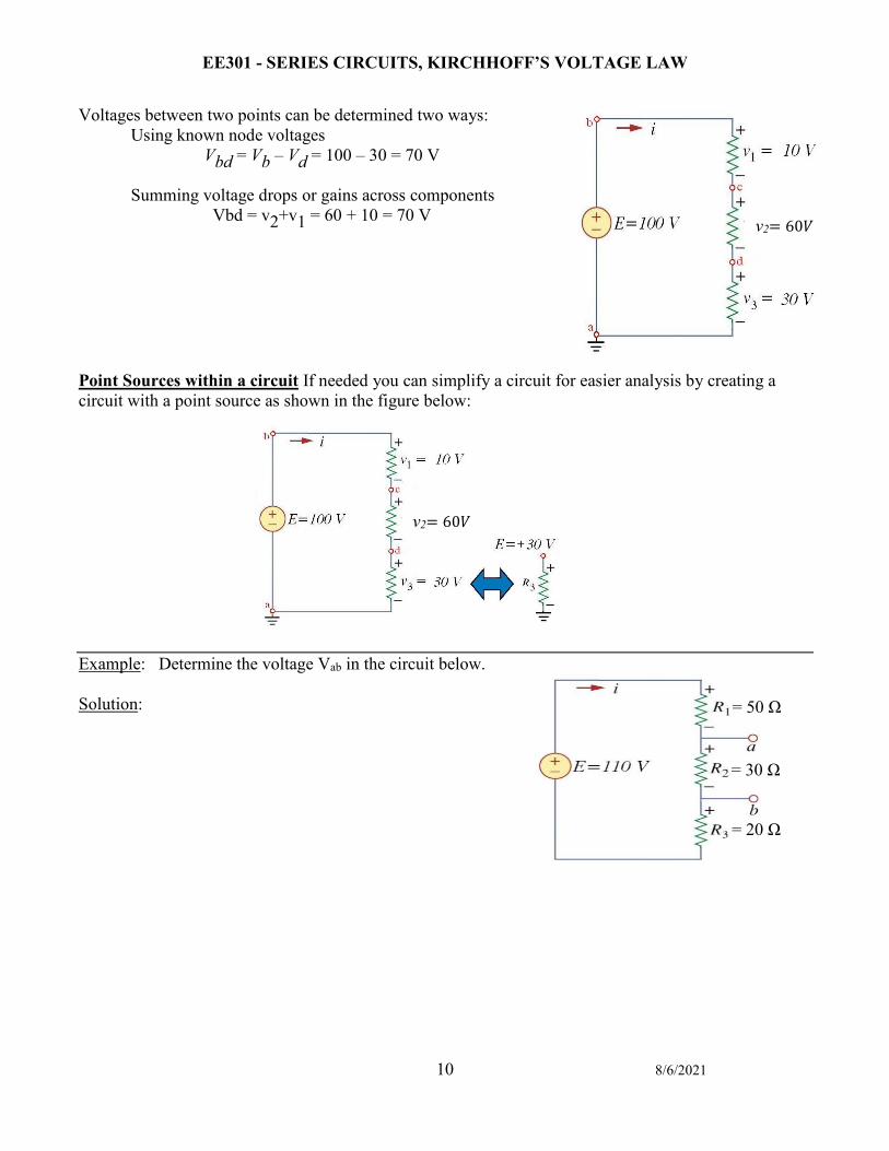
Voltages between two points can be determined two ways: Using known node voltages
Vbd = Vb – Vd = 100 – 30 = 70 V
Summing voltage drops or gains across components Vbd = v2+v1 = 60 + 10 = 70 V
Point Sources within a circuit If needed you can simplify a circuit for easier analysis by creating a circuit with a point source as shown in the figure below: Example: Determine the voltage Vab in the circuit below. Solution:
v2= 60𝑉𝑉
= 30 Ω
= 50 Ω
= 20 Ω
v2= 60𝑉𝑉
v2= 60𝑉𝑉
EE301 - SERIES CIRCUITS, KIRCHHOFF’S VOLTAGE LAW
11 8/6/2021
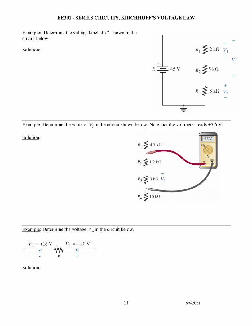
Example: Determine the voltage labeled V ′ shown in the circuit below. Solution: Example: Determine the value of 3V in the circuit shown below. Note that the voltmeter reads +5.6 V. Solution: Example: Determine the voltage abV in the circuit below.
Solution:
EE301 - SERIES CIRCUITS, KIRCHHOFF’S VOLTAGE LAW
12 8/6/2021
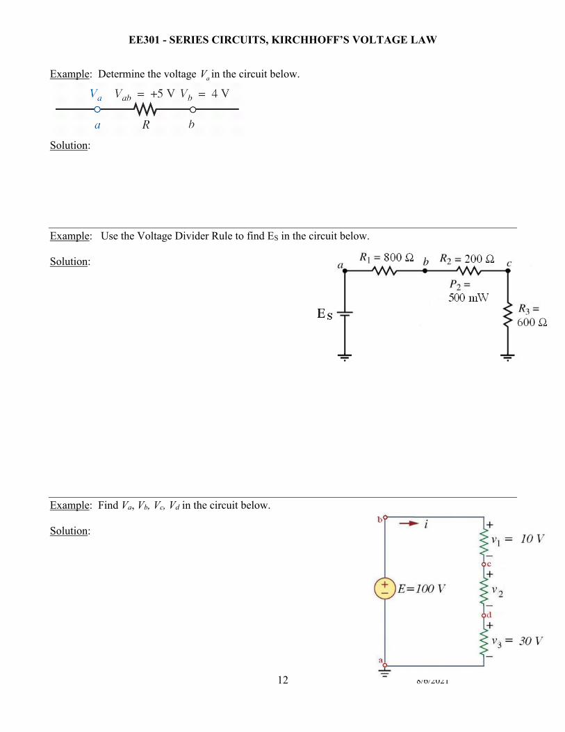
Example: Determine the voltage aV in the circuit below.
Solution: Example: Use the Voltage Divider Rule to find ES in the circuit below. Solution: Example: Find Va, Vb, Vc, Vd in the circuit below. Solution:
EE301 - SERIES CIRCUITS, KIRCHHOFF’S VOLTAGE LAW
13 8/6/2021
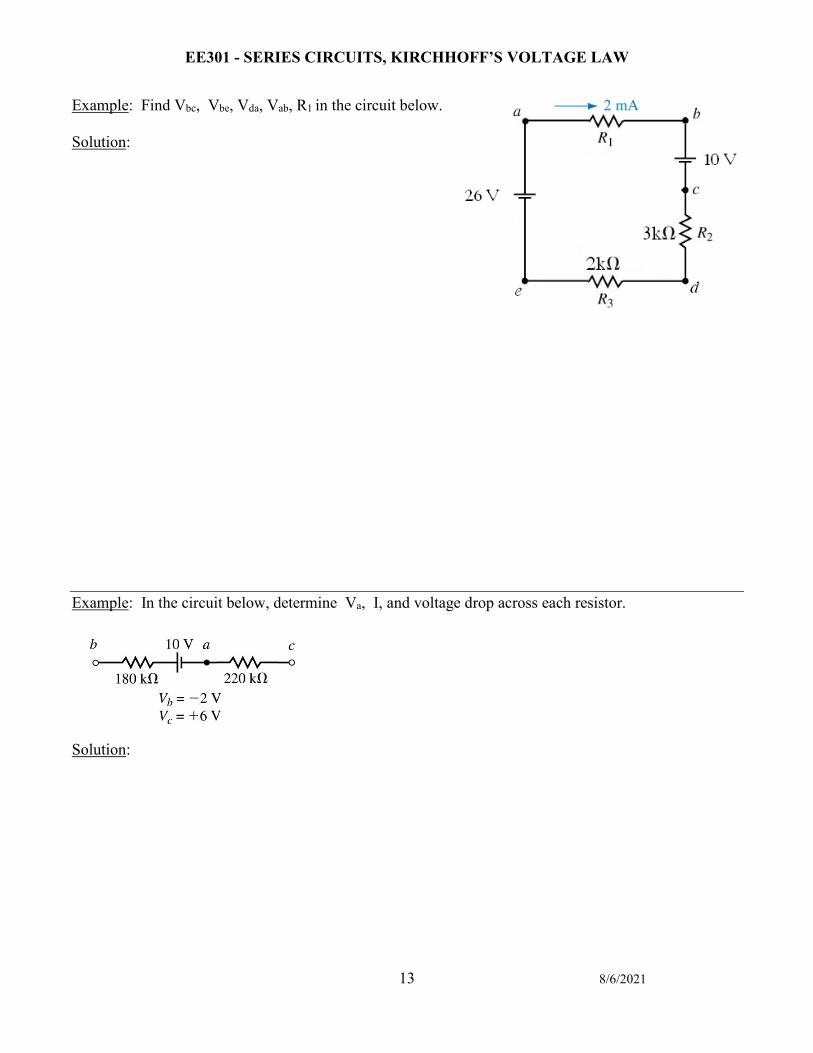
Example: Find Vbc, Vbe, Vda, Vab, R1 in the circuit below. Solution: Example: In the circuit below, determine Va, I, and voltage drop across each resistor.
Solution: