Embed Size (px)
Citation preview
EECC550 - ShaabanEECC550 - Shaaban#1 Lec # 11 Spring 2001 5-14-2001
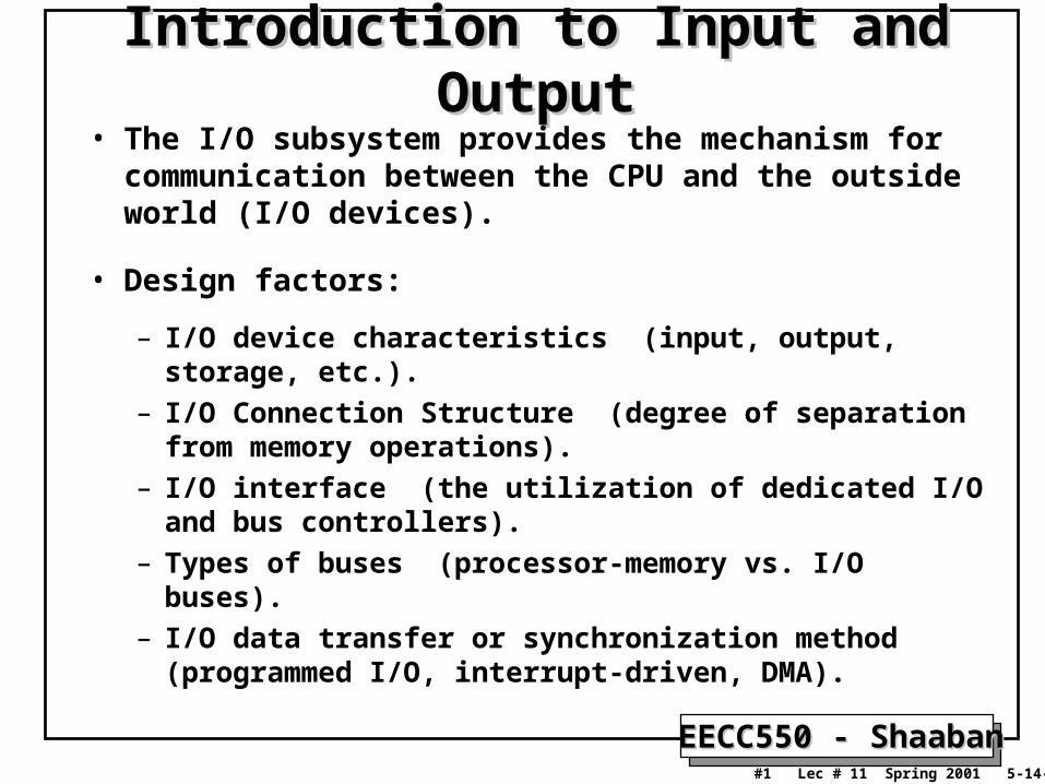
Introduction to Input and OutputIntroduction to Input and Output• The I/O subsystem provides the mechanism for
communication between the CPU and the outside world (I/O devices).
• Design factors:
– I/O device characteristics (input, output, storage, etc.).
– I/O Connection Structure (degree of separation from memory operations).
– I/O interface (the utilization of dedicated I/O and bus controllers).
– Types of buses (processor-memory vs. I/O buses).
– I/O data transfer or synchronization method (programmed I/O, interrupt-driven, DMA).

EECC550 - ShaabanEECC550 - Shaaban#2 Lec # 11 Spring 2001 5-14-2001
Typical CPU-Memory and I/O Bus InterfaceTypical CPU-Memory and I/O Bus Interface

EECC550 - ShaabanEECC550 - Shaaban#3 Lec # 11 Spring 2001 5-14-2001
Impact of I/O on System Performance• CPU Performance: Improvement of 60% per year.
• I/O Sub-System Performance: Limited by mechanical delays (disk I/O). Improvement less than 10% per year (IO rate per sec or MB per sec).
• From Amdahl's Law: overall system speed-up is limited by the slowest component:
If I/O is 10% of current processing time:• Increasing CPU performance by 10 times
Only 5 times system performance increase (50% loss in performance)
• Increasing CPU performance by 100 times Only 10 times system performance increase (90% loss of performance)
• The I/O system performance bottleneck diminishes the benefit of faster CPUs on overall system performance.

EECC550 - ShaabanEECC550 - Shaaban#4 Lec # 11 Spring 2001 5-14-2001
I/O Device CharacteristicsI/O Device Characteristics• I/O devices are characterized according to:
– Behavior: • Input (read once).
• Output (write only, cannot be read).
• Storage (can be reread and usually rewritten).
– Partner: Either a human or a machine at the other end of the I/O device.
– Data rate: The peak rate at which data can be transferred between the I/O device and main memory or CPU.

EECC550 - ShaabanEECC550 - Shaaban#5 Lec # 11 Spring 2001 5-14-2001
The Diversity of I/O DevicesThe Diversity of I/O DevicesDevice Behavior Partner Data Rate
(KB/sec)
Keyboard Input Human 0.01
Mouse Input Human 0.02
Line Printer Output Human 1.00
Floppy disk Storage Machine 50.00
Laser Printer Output Human 100.00
Optical Disk Storage Machine 500.00
Magnetic Disk Storage Machine 5,000.00
Network-LAN Input or Output Machine 20 – 1,000.00
Graphics Display Output Human 30,000.00

EECC550 - ShaabanEECC550 - Shaaban#6 Lec # 11 Spring 2001 5-14-2001
I/O System PerformanceI/O System Performance• I/O System performance depends on many aspects of the system (“limited
by weakest link in the chain”):
– The CPU
– The memory system:
• Internal and external caches.
• Main Memory.
– The underlying interconnection (buses).
– The I/O controller or hardware interface.
– The I/O device itself.
– I/O Data Transfer Method.
– The speed of the I/O software (Operating System).
– The efficiency of the software’s use of the I/O devices.
• Two common performance metrics:
– Throughput: I/O bandwidth or I/O operations/second
– Response time: Latency.

EECC550 - ShaabanEECC550 - Shaaban#7 Lec # 11 Spring 2001 5-14-2001
Producer ServerQueue
I/O PerformanceI/O Performance: Simple Producer-Server ModelSimple Producer-Server Model
• Throughput:– The number of tasks completed by the server in unit time.– In order to get the highest possible throughput:
• The server should never be idle.• The queue should never be empty.
• Response time:– Begins when a task is placed in the queue– Ends when it is completed by the server– In order to minimize the response time:
• The queue should be empty.• The server will be idle at times.

EECC550 - ShaabanEECC550 - Shaaban#8 Lec # 11 Spring 2001 5-14-2001
Throughput Versus Response TimeThroughput Versus Response Time
20% 40% 60% 80% 100%
ResponseTime (ms)
100
200
300
Percentage of maximum throughput

EECC550 - ShaabanEECC550 - Shaaban#9 Lec # 11 Spring 2001 5-14-2001
I/O PerformanceI/O Performance: Throughput EnhancementThroughput Enhancement
Producer
ServerQueue
QueueServer
• In general throughput can be improved by:– Throwing more hardware at the problem.
– Reduces load-related latency.
• Response time is much harder to reduce.

EECC550 - ShaabanEECC550 - Shaaban#10 Lec # 11 Spring 2001 5-14-2001
Magnetic DisksMagnetic DisksCharacteristics:Characteristics:• Diameter: 2.5in - 5.25in
• Rotational speed: 3,600RPM-10,000 RPM
• Tracks per surface.
• Sectors per track: Outer tracks contain
more sectors.
• Recording or Areal Density: Tracks/in X Bits/in
• Cost Per Megabyte.
• Seek Time: The time needed to move the
read/write head arm.
Reported values: Minimum, Maximum, Average.
• Rotation Latency or Delay:
The time for the requested sector to be under
the read/write head.
• Transfer time: The time needed to transfer a sector of bits.
• Type of controller/interface: SCSI, EIDE
• Disk Controller delay or time.
• Average time to access a sector of data =
average seek time + average rotational delay + transfer time +
disk controller overhead + Queueing Delay
EECC550 - ShaabanEECC550 - Shaaban#11 Lec # 11 Spring 2001 5-14-2001
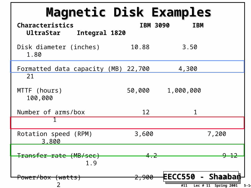
Magnetic Disk ExamplesMagnetic Disk ExamplesCharacteristics IBM 3090 IBM UltraStar Integral
1820
Disk diameter (inches) 10.88 3.50 1.80
Formatted data capacity (MB) 22,700 4,300 21
MTTF (hours) 50,000 1,000,000 100,000
Number of arms/box 12 1 1
Rotation speed (RPM) 3,600 7,200 3,800
Transfer rate (MB/sec) 4.2 9-12 1.9
Power/box (watts) 2,900 13 2
MB/watt 8 102 10.5
Volume (cubic feet) 97 0.13 0.02
MB/cubic feet 234 33000 1050

EECC550 - ShaabanEECC550 - Shaaban#12 Lec # 11 Spring 2001 5-14-2001
Disk I/O PerformanceDisk I/O Performance
ProcessorQueue
DiskController
Disk
Service RateRequest Rate
Queue
DiskController
Disk
• Disk Access Time = Seek time + Rotational Latency + Transfer time
+ Controller Time + Queueing Delay
• Estimating Queue Length:
– Utilization = U = Request Rate / Service Rate
– Mean Queue Length = U / (1 - U)
– As Request Rate -> Service Rate
• Mean Queue Length -> Infinity

EECC550 - ShaabanEECC550 - Shaaban#13 Lec # 11 Spring 2001 5-14-2001
Disk Access Time ExampleDisk Access Time Example• Given the following Disk Parameters:
– Transfer size is 8K bytes
– Advertised average seek is 12 ms
– Disk spins at 7200 RPM
– Transfer rate is 4 MB/sec
• Controller overhead is 2 ms• Assume that the disk is idle, so no queuing delay exist.
• What is Average Disk Access Time for a 512-byte Sector?– Ave. seek + ave. rot delay + transfer time + controller overhead +
Queueing Delay
– 12 ms + 0.5/(7200 RPM/60) + 8 KB/4 MB/s + 2 ms + 0
– 12 + 4.15 + 2 + 2 + 0 = 20 ms
• Advertised seek time assumes no locality: typically 1/4 to 1/3 advertised seek time: 20 ms => 12 ms
EECC550 - ShaabanEECC550 - Shaaban#14 Lec # 11 Spring 2001 5-14-2001
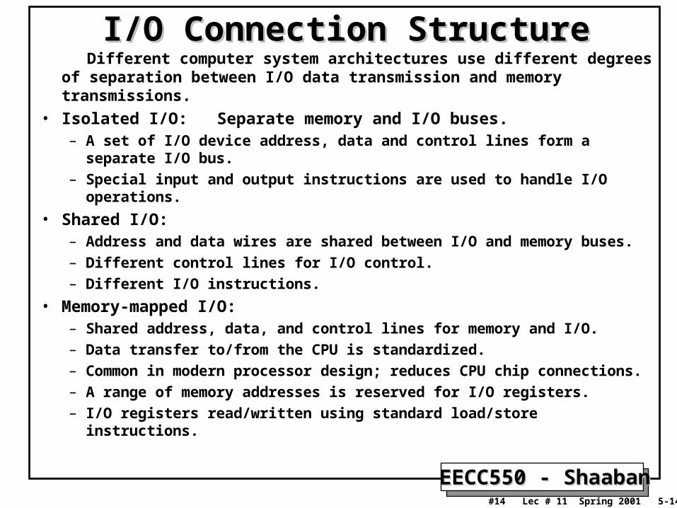
I/O Connection StructureI/O Connection Structure Different computer system architectures use different degrees of
separation between I/O data transmission and memory transmissions.
• Isolated I/O: Separate memory and I/O buses.– A set of I/O device address, data and control lines form a separate I/O
bus.– Special input and output instructions are used to handle I/O operations.
• Shared I/O: – Address and data wires are shared between I/O and memory buses.– Different control lines for I/O control.– Different I/O instructions.
• Memory-mapped I/O: – Shared address, data, and control lines for memory and I/O.– Data transfer to/from the CPU is standardized.– Common in modern processor design; reduces CPU chip connections.– A range of memory addresses is reserved for I/O registers.– I/O registers read/written using standard load/store instructions.

EECC550 - ShaabanEECC550 - Shaaban#15 Lec # 11 Spring 2001 5-14-2001
I/O InterfaceI/O InterfaceI/O Interface, controller or I/O bus adapter:
– Specific to each type of I/O device.
– To the CPU, and I/O device, it consists of a set of control and data registers within the I/O address space.
– On the I/O device side, it forms a localized I/O bus which can be shared by several I/O devices.
– Handles I/O details such as:
• Assembling bits into words,
• Low-level error detection and correction.
• Accepting or providing words in word-sized I/O registers.
• Presents a uniform interface to the CPU regardless of I/O device.

EECC550 - ShaabanEECC550 - Shaaban#16 Lec # 11 Spring 2001 5-14-2001
Types of BusesTypes of Buses• Processor-Memory Bus (sometimes also called Backplane Bus):
– Offers very high-speed and low latency.
– Matched to the memory system to maximize memory-processor bandwidth.
– Usually design-specific, though some designs use standard backplane buses.
• I/O buses (sometimes called a channel ):
– Follow bus standards.
– Usually formed by I/O interface adapters to handle many types of connected I/O devices.
– Wide range in the data bandwidth and latency
– Not usually interfaced directly to memory but use a processor-memory or backplane bus.
– Examples: Sun’s SBus, Intel’s PCI, SCSI.

EECC550 - ShaabanEECC550 - Shaaban#17 Lec # 11 Spring 2001 5-14-2001
Processor-Memory, I/O Bus Organization

EECC550 - ShaabanEECC550 - Shaaban#18 Lec # 11 Spring 2001 5-14-2001
Example: Pentium System OrganizationExample: Pentium System Organization
Processor/MemoryBus
I/O Backplane Bus: PCI Bus
I/O BussesChipset: South Bridge
L2 Cache Main Memory/ControllerChipset: North Bridge
EECC550 - ShaabanEECC550 - Shaaban#19 Lec # 11 Spring 2001 5-14-2001
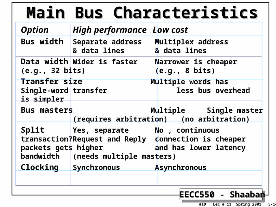
Main Bus CharacteristicsMain Bus CharacteristicsOption High performance Low costBus width Separate address Multiplex address
& data lines & data lines
Data width Wider is faster Narrower is cheaper (e.g., 32 bits) (e.g., 8 bits)
Transfer size Multiple words has Single-word transferless bus overhead is simpler
Bus masters Multiple Single master(requires arbitration) (no arbitration)
Split Yes, separate No , continuous transaction?Request and Reply connection is cheaper packets gets higher and has lower latencybandwidth(needs multiple masters)
Clocking Synchronous Asynchronous

EECC550 - ShaabanEECC550 - Shaaban#20 Lec # 11 Spring 2001 5-14-2001
Synchronous Vs. Asynchronous BusesSynchronous Vs. Asynchronous Buses• Synchronous Bus:
– A clock is included in the control lines.
– A fixed communication protocol relative to the clock is used. (memory-processor communication).
• Asynchronous Bus:– Not clocked.
– A handshaking protocol is used: A series of steps in which the sender and receiver proceed to the next step when both agree using an additional set of control lines.
– A device requesting a word from memory may use the lines:• ReadReq: Read request from memory. Address put on the data
lines at the same time.• DataRdy: Indicated that a data word is now ready.• Ack: Used to acknowledge the ReadReq or DataRdy signal of the
other party.

EECC550 - ShaabanEECC550 - Shaaban#21 Lec # 11 Spring 2001 5-14-2001
Asynchronous Bus Handshaking Asynchronous Bus Handshaking Protocol StepsProtocol Steps
Details in Figure 8.10 page 661

EECC550 - ShaabanEECC550 - Shaaban#22 Lec # 11 Spring 2001 5-14-2001
Typical Synchronous Bus TransactionTypical Synchronous Bus Transaction
BusReq
BusGrant
Cmd+AddrR/WAddress
Data1 Data2Data

EECC550 - ShaabanEECC550 - Shaaban#23 Lec # 11 Spring 2001 5-14-2001
Split-transaction BusSplit-transaction Bus
A read transaction is tagged and broken into:• A read request-transaction containing the address• A memory-reply transaction that contains the data address on the bus refers to a later memory access
• Used when multiple bus masters are present,• Also known as a pipelined or a packet-switched bus• The bus is available to other bus masters while a memory operation is in progress
Higher bus bandwidth, but also higher bus latency

EECC550 - ShaabanEECC550 - Shaaban#24 Lec # 11 Spring 2001 5-14-2001
Obtaining Access to the Bus: Bus ArbitrationObtaining Access to the Bus: Bus ArbitrationBus arbitration decides which device (bus master) gets the use of the bus next. Several schemes exist:
• A single bus master: – All bus requests are controlled by the processor.
• Daisy chain arbitration:– A bus grant line runs through the devices from the highest
priority to lowest (priority determined by the position on the bus).
– A high-priority device intercepts the bus grant signal, not allowing a low-priority device to see it (VME bus).
• Centralized, parallel arbitration:– Multiple request lines for each device.– A centralized arbiter chooses a requesting device and
notifies it that it is now the bus master.

EECC550 - ShaabanEECC550 - Shaaban#25 Lec # 11 Spring 2001 5-14-2001
Obtaining Access to the Bus: Bus ArbitrationObtaining Access to the Bus: Bus Arbitration
• Distributed arbitration by self-selection:
– Use multiple request lines for each device
– Each device requesting the bus places a code indicating its identity on the bus.
– The requesting devices determine the highest priority device to control the bus.
– Requires more lines for request signals (Apple NuBus).
• Distributed arbitration by collision detection:
– Each device independently request the bus.
– Multiple simultaneous requests result in a collision.
– The collision is detected and a scheme to decide among the colliding requests is used (Ethernet).

EECC550 - ShaabanEECC550 - Shaaban#26 Lec # 11 Spring 2001 5-14-2001
Bus Transactions with a Single Master
Details in Figure 8.12 page 668

EECC550 - ShaabanEECC550 - Shaaban#27 Lec # 11 Spring 2001 5-14-2001
Daisy Chain Bus ArbitrationDaisy Chain Bus Arbitration
Details in Figure 8.13 page 670

EECC550 - ShaabanEECC550 - Shaaban#28 Lec # 11 Spring 2001 5-14-2001
I/O Bus ExamplesI/O Bus ExamplesBus SBus TurboChannel MicroChannel PCI
Originator Sun DEC IBM Intel
Clock Rate (MHz) 16-25 12.5-25 async 33
Addressing Virtual Physical Physical Physical
Data Sizes (bits) 8,16,32 8,16,24,32 8,16,24,32,648,16,24,32,64
Master Multi Single Multi Multi
Arbitration Central Central Central Central
32 bit read (MB/s) 33 25 20 33
Peak (MB/s) 89 84 75 111 (222)
Max Power (W) 16 26 13 25

EECC550 - ShaabanEECC550 - Shaaban#29 Lec # 11 Spring 2001 5-14-2001
CPU-Memory Bus ExamplesCPU-Memory Bus ExamplesBus Summit Challenge XDBus
Originator HP SGI Sun
Clock Rate (MHz) 60 48 66
Split transaction? Yes Yes Yes
Address lines 48 40 ??
Data lines 128 256 144 (parity)
Data Sizes (bits) 512 1024 512
Clocks/transfer 4 5 4
Peak (MB/s) 960 1200 1056
Master Multi Multi Multi
Arbitration Central Central Central
Addressing Physical Physical Physical
Slots 16 9 10
Busses/system 1 1 2
Length 13 inches 12 inches 17 inches

EECC550 - ShaabanEECC550 - Shaaban#30 Lec # 11 Spring 2001 5-14-2001
SCSI: Small Computer System InterfaceSCSI: Small Computer System Interface• Clock rate: 5 MHz / 10 MHz (fast) / 20 MHz (ultra).
• Width: n = 8 bits / 16 bits (wide); up to n – 1 devices to communicate on a bus or “string”.
• Devices can be slave (“target”) or master (“initiator”).
• SCSI protocol: A series of “phases”, during which specific actions are taken by the controller and the SCSI disks and devices.
– Bus Free: No device is currently accessing the bus– Arbitration: When the SCSI bus goes free, multiple devices may request
(arbitrate for) the bus; fixed priority by address– Selection: Informs the target that it will participate (Reselection if
disconnected)– Command: The initiator reads the SCSI command bytes from host memory
and sends them to the target
– Data Transfer: data in or out, initiator: target– Message Phase: message in or out, initiator: target (identify, save/restore data
pointer, disconnect, command complete)
– Status Phase: target, just before command complete.
EECC550 - ShaabanEECC550 - Shaaban#31 Lec # 11 Spring 2001 5-14-2001
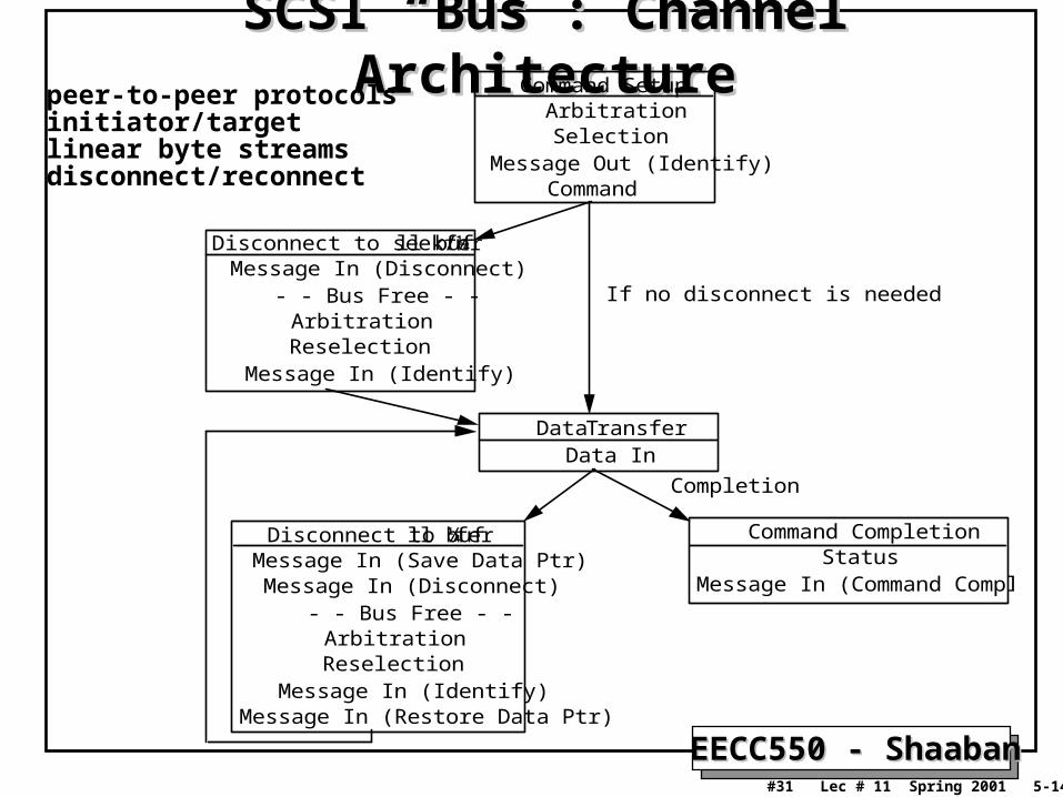
SCSI “Bus”: Channel ArchitectureSCSI “Bus”: Channel ArchitectureCommand Setup
ArbitrationSelection
Message Out (Identify)Command
Disconnect to seek/¼ll bufferMessage In (Disconnect)
- - Bus Free - -ArbitrationReselection
Message In (Identify)
Data TransferData In
Disconnect to ¼ll bufferMessage In (Save Data Ptr)
Message In (Disconnect)- - Bus Free - -
ArbitrationReselection
Message In (Identify)
Command CompletionStatus
Message In (Command Complete)
If no disconnect is needed
Completion
Message In (Restore Data Ptr)
peer-to-peer protocolsinitiator/targetlinear byte streamsdisconnect/reconnect

EECC550 - ShaabanEECC550 - Shaaban#32 Lec # 11 Spring 2001 5-14-2001
IEEE1394 High-Speed Serial Bus (Firewire)IEEE1394 High-Speed Serial Bus (Firewire)• A digital interface: No need to convert digital data into analog
signals and tolerate a loss of data integrity, • Physically small: A thin serial cable can replace larger and more
expensive interfaces, • Easy to use: No need for terminators, device IDs, or elaborate
setup.• Hot pluggable - users can add or remove 1394 devices with the bus
active.• Inexpensive - priced for consumer products.• Scalable architecture: May mix 100, 200, and 400 Mbps devices on
a bus.• Flexible topology: support of daisy chaining and branching for true
peer-to-peer communication, • Fast: Even multimedia data can be guaranteed its bandwidth for
just-in-time delivery, and • Non-proprietary.• Mixed asynchronous and isochronous traffic.

EECC550 - ShaabanEECC550 - Shaaban#33 Lec # 11 Spring 2001 5-14-2001
Firewire OperationFirewire Operation
isochronouschannel #1time slot
Packet Frame = 125 µsecs
isochronouschannel #1time slot
Time slot available for asynchronous transport
Timing indicator
• Fixed frame is divided into preallocated isochronous slots + best effort asynchronous slot
• Each slot has packet containing “ID” command and data
• Example: digital video camera can expect to send one 64 byte packet every 125 µs:
80 * 1024 * 64 = 5MB/s

EECC550 - ShaabanEECC550 - Shaaban#34 Lec # 11 Spring 2001 5-14-2001
I/O Data Transfer MethodsI/O Data Transfer Methods• Programmed I/O (PIO): PollingProgrammed I/O (PIO): Polling
– The I/O device puts its status information in a status register.
– The processor must periodically check the status register.
– The processor is totally in control and does all the work.
– Very wasteful of processor time.
• Interrupt-Driven I/O:Interrupt-Driven I/O:– An interrupt line from the I/O device to the CPU is used to
generate an I/O interrupt indicating that the I/O device needs CPU attention.
– The interrupting device places its identity in an interrupt vector.
– Once an I/O interrupt is detected the current instruction is completed and an I/O interrupt handling routine is executed to service the device.
EECC550 - ShaabanEECC550 - Shaaban#35 Lec # 11 Spring 2001 5-14-2001
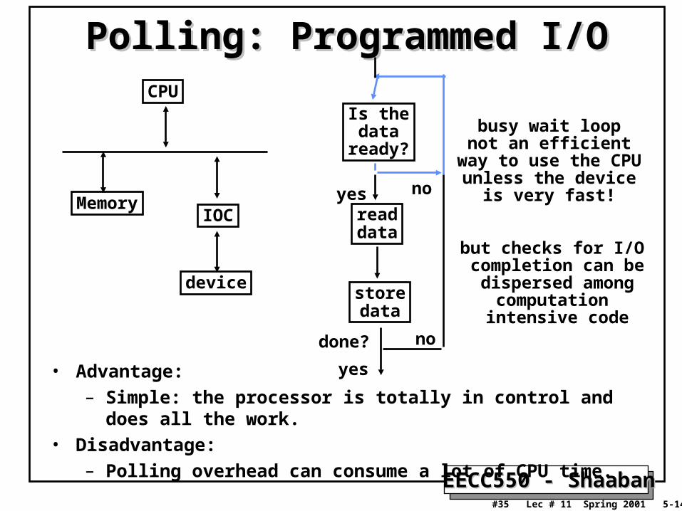
Polling: Programmed I/OPolling: Programmed I/OCPU
IOC
device
Memory
Is thedata
ready?
readdata
storedata
yes no
done? no
yes
busy wait loopnot an efficient
way to use the CPUunless the device
is very fast!
but checks for I/O completion can bedispersed among
computation intensive code
• Advantage: – Simple: the processor is totally in control and does all the work.
• Disadvantage:– Polling overhead can consume a lot of CPU time.

EECC550 - ShaabanEECC550 - Shaaban#36 Lec # 11 Spring 2001 5-14-2001
Polling Example
Example in textbook pages 676-678

EECC550 - ShaabanEECC550 - Shaaban#37 Lec # 11 Spring 2001 5-14-2001
Interrupt-Driven Data TransferInterrupt-Driven Data TransferCPU
IOC
device
Memory
addsubandornop
readstore...rti
memory
userprogram(1) I/O
interrupt
(2) save PC
(3) interruptservice addr
(4):
• Advantage:
– User program progress is only halted during actual transfer.
• Disadvantage, special hardware is needed to:– Cause an interrupt (I/O device).– Detect an interrupt (processor).– Save the proper states to resume after the interrupt (processor).

EECC550 - ShaabanEECC550 - Shaaban#38 Lec # 11 Spring 2001 5-14-2001
Interrupt-driven I/O Example
Example in textbook pages 679-680

EECC550 - ShaabanEECC550 - Shaaban#39 Lec # 11 Spring 2001 5-14-2001
I/O Data Transfer MethodsI/O Data Transfer MethodsDirect Memory Access (DMA):Direct Memory Access (DMA): • Implemented with a specialized controller that transfers data between
an I/O device and memory independent of the processor.
• The DMA controller becomes the bus master and directs reads and writes between itself and memory.
• Interrupts are still used only on completion of the transfer or when an error occurs.
• DMA transfer steps:– The CPU sets up DMA by supplying device identity, operation,
memory address of source and destination of data, the number of bytes to be transferred.
– The DMA controller starts the operation. When the data is available it transfers the data, including generating memory addresses for data to be transferred.
– Once the DMA transfer is complete, the controller interrupts the processor, which determines whether the entire operation is complete.

EECC550 - ShaabanEECC550 - Shaaban#40 Lec # 11 Spring 2001 5-14-2001
Direct Memory Access (DMA) Example
Example in textbook pages 681-682

EECC550 - ShaabanEECC550 - Shaaban#41 Lec # 11 Spring 2001 5-14-2001
System I/O Performance EvaluationSystem I/O Performance Evaluation• When designing an I/O system, the components that
make it up should be balanced in terms of performance.
• Steps for evaluating system I/O performance:– List types of devices and buses in system.
– Record the CPU resource demands of device.• CPU clock cycles directly for I/O (e.g. initiate, interrupts, complete)
• CPU clock cycles due to stalls waiting for I/O
• CPU clock cycles to recover from I/O activity (e.g., cache flush)
– List memory and I/O bus resource demands.
– List the performance parameters for I/O devices.
– Find the peak I/O performance for each system component:• CPU, Memory, System Bus, I/O Bus, I/O Devices.
– The system component with the lowest I/O performance becomes the limiting factor or bottleneck that determines overall system I/O performance.

EECC550 - ShaabanEECC550 - Shaaban#42 Lec # 11 Spring 2001 5-14-2001
System I/O Performance ExampleSystem I/O Performance Example• Assume the following system components:
– 500 MIPS CPU
– 16-byte wide memory system with 100 ns cycle time
– 200 MB/sec I/O bus
– 20 20 MB/sec SCSI-2 buses, with 1 ms controller overhead
– 5 disks per SCSI bus: 8 ms seek, 7,200 RPMS, 6MB/sec
• Other assumptions– All devices may be used to 100% capacity.
– Disk I/O requests are distributed evenly among all disks.
– Average disk I/O size is 16 KB
– 10,000 CPU instructions for a disk I/O
• What is the average I/O operations per second (IOPS)? What is the average I/O bandwidth?
EECC550 - ShaabanEECC550 - Shaaban#43 Lec # 11 Spring 2001 5-14-2001
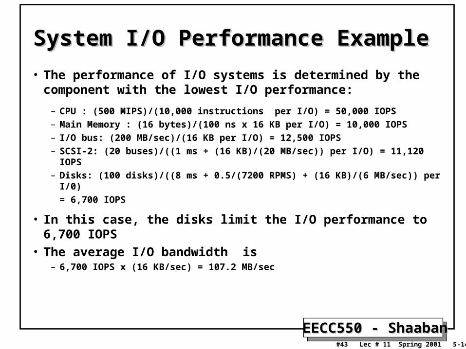
• The performance of I/O systems is determined by the component with the lowest I/O performance:
– CPU : (500 MIPS)/(10,000 instructions per I/O) = 50,000 IOPS
– Main Memory : (16 bytes)/(100 ns x 16 KB per I/O) = 10,000 IOPS
– I/O bus: (200 MB/sec)/(16 KB per I/O) = 12,500 IOPS
– SCSI-2: (20 buses)/((1 ms + (16 KB)/(20 MB/sec)) per I/O) = 11,120 IOPS
– Disks: (100 disks)/((8 ms + 0.5/(7200 RPMS) + (16 KB)/(6 MB/sec)) per I/0)
= 6,700 IOPS
• In this case, the disks limit the I/O performance to 6,700 IOPS
• The average I/O bandwidth is– 6,700 IOPS x (16 KB/sec) = 107.2 MB/sec
System I/O Performance ExampleSystem I/O Performance Example