Embed Size (px)
Citation preview
EECC756 - ShaabanEECC756 - Shaaban#1 lec # 10 Spring2002 4-23-2002
Generic Multiprocessor ArchitectureGeneric Multiprocessor Architecture
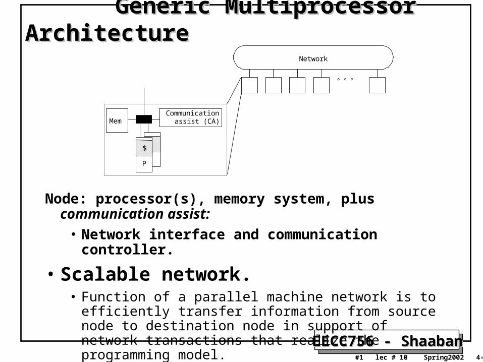
Node: processor(s), memory system, plus communication assist:
• Network interface and communication controller.
• Scalable network.• Function of a parallel machine network is to efficiently transfer
information from source node to destination node in support of network transactions that realize the programming model.
• Network performance should scale up as its size is increased.
Mem
Network
P
$
Communicationassist (CA)
EECC756 - ShaabanEECC756 - Shaaban#2 lec # 10 Spring2002 4-23-2002
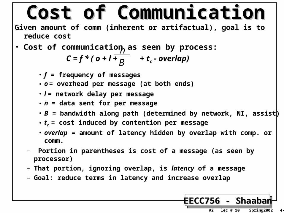
Cost of CommunicationCost of CommunicationGiven amount of comm (inherent or artifactual), goal is to reduce cost
• Cost of communication as seen by process:
C = f * ( o + l + + tc - overlap)
• f = frequency of messages• o = overhead per message (at both ends)
• l = network delay per message
• n = data sent for per message
• B = bandwidth along path (determined by network, NI, assist)
• tc = cost induced by contention per message
• overlap = amount of latency hidden by overlap with comp. or comm.
– Portion in parentheses is cost of a message (as seen by processor)
– That portion, ignoring overlap, is latency of a message
– Goal: reduce terms in latency and increase overlap
nB
EECC756 - ShaabanEECC756 - Shaaban#3 lec # 10 Spring2002 4-23-2002
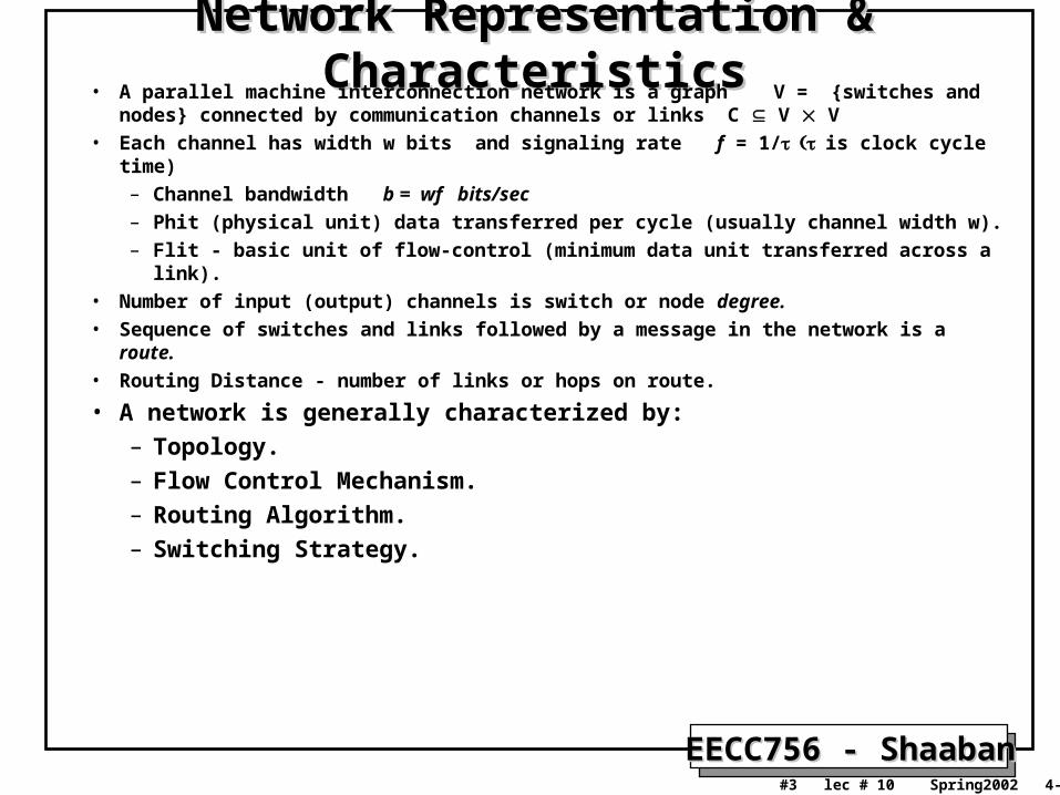
Network Representation & CharacteristicsNetwork Representation & Characteristics• A parallel machine interconnection network is a graph V = {switches and nodes}
connected by communication channels or links C V V• Each channel has width w bits and signaling rate f = 1/is clock cycle time)
– Channel bandwidth b = wf bits/sec
– Phit (physical unit) data transferred per cycle (usually channel width w).
– Flit - basic unit of flow-control (minimum data unit transferred across a link).• Number of input (output) channels is switch or node degree.• Sequence of switches and links followed by a message in the network is a route. • Routing Distance - number of links or hops on route.
• A network is generally characterized by:– Topology.– Flow Control Mechanism.– Routing Algorithm.– Switching Strategy.
EECC756 - ShaabanEECC756 - Shaaban#4 lec # 10 Spring2002 4-23-2002
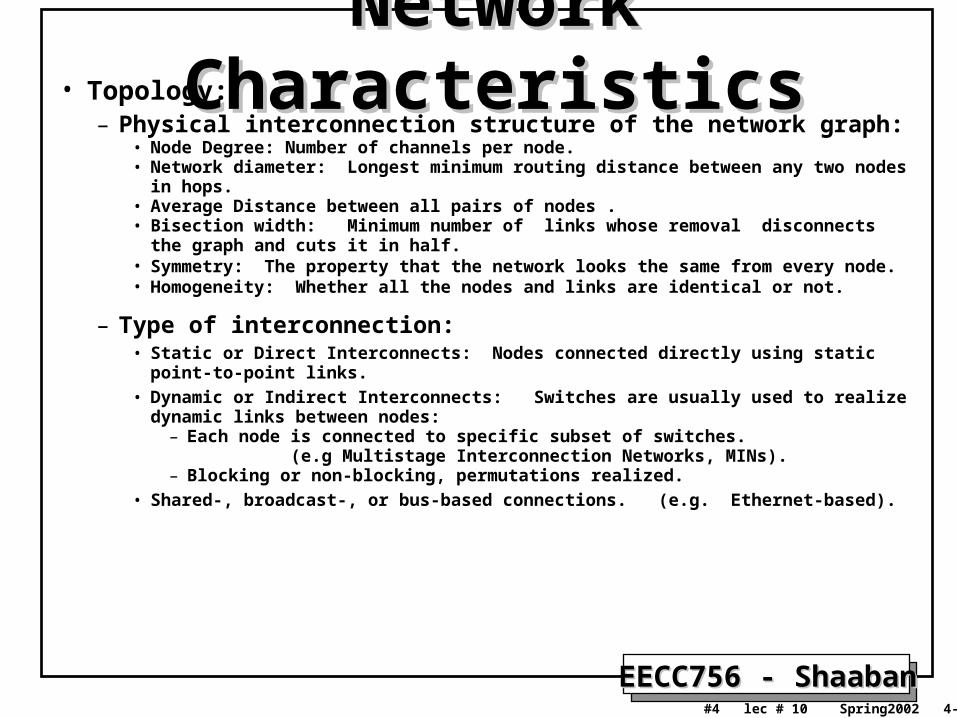
Network CharacteristicsNetwork Characteristics• Topology:
– Physical interconnection structure of the network graph:• Node Degree: Number of channels per node. • Network diameter: Longest minimum routing distance between any two nodes in hops.• Average Distance between all pairs of nodes .• Bisection width: Minimum number of links whose removal disconnects the graph
and cuts it in half.• Symmetry: The property that the network looks the same from every node.• Homogeneity: Whether all the nodes and links are identical or not.
– Type of interconnection:• Static or Direct Interconnects: Nodes connected directly using static point-to-point
links.
• Dynamic or Indirect Interconnects: Switches are usually used to realize dynamic links between nodes:
– Each node is connected to specific subset of switches. (e.g Multistage Interconnection Networks, MINs).
– Blocking or non-blocking, permutations realized.
• Shared-, broadcast-, or bus-based connections. (e.g. Ethernet-based).
EECC756 - ShaabanEECC756 - Shaaban#5 lec # 10 Spring2002 4-23-2002
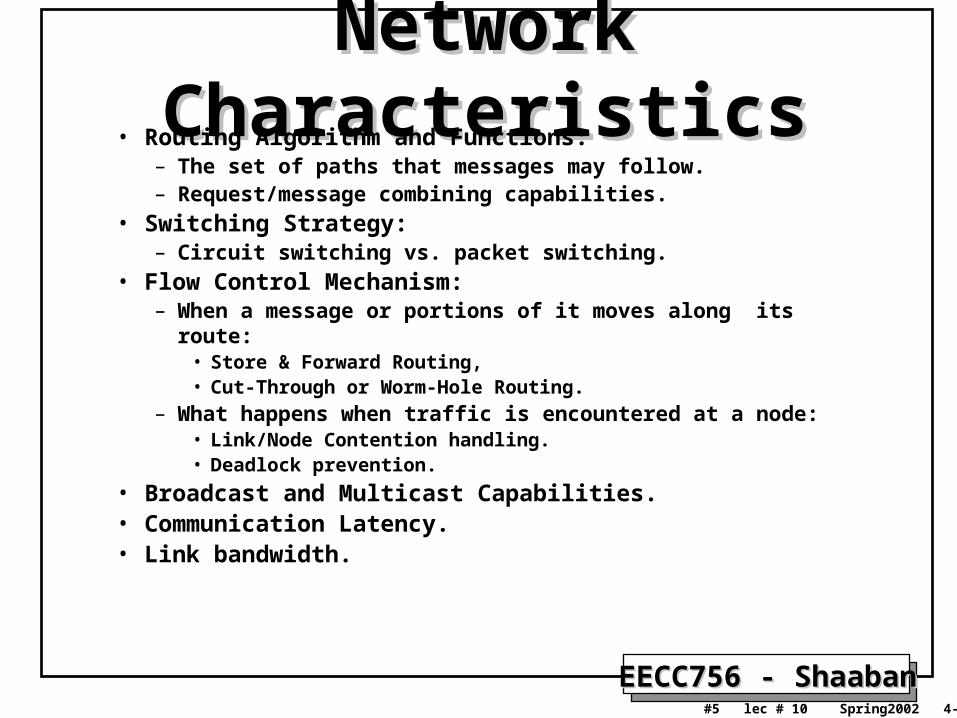
Network CharacteristicsNetwork Characteristics• Routing Algorithm and Functions:
– The set of paths that messages may follow.– Request/message combining capabilities.
• Switching Strategy:– Circuit switching vs. packet switching.
• Flow Control Mechanism:– When a message or portions of it moves along its route:
• Store & Forward Routing,• Cut-Through or Worm-Hole Routing.
– What happens when traffic is encountered at a node:• Link/Node Contention handling.• Deadlock prevention.
• Broadcast and Multicast Capabilities.• Communication Latency.• Link bandwidth.
EECC756 - ShaabanEECC756 - Shaaban#6 lec # 10 Spring2002 4-23-2002
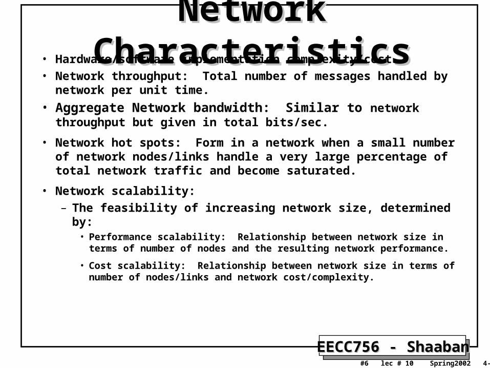
Network CharacteristicsNetwork Characteristics• Hardware/software implementation complexity/cost.• Network throughput: Total number of messages handled by network
per unit time.
• Aggregate Network bandwidth: Similar to network throughput but given in total bits/sec.
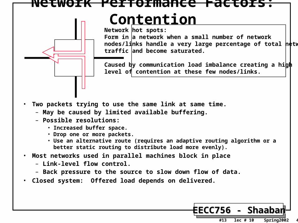
• Network hot spots: Form in a network when a small number of network nodes/links handle a very large percentage of total network traffic and become saturated.
• Network scalability: – The feasibility of increasing network size, determined by:
• Performance scalability: Relationship between network size in terms of number of nodes and the resulting network performance.
• Cost scalability: Relationship between network size in terms of number of nodes/links and network cost/complexity.
EECC756 - ShaabanEECC756 - Shaaban#7 lec # 10 Spring2002 4-23-2002
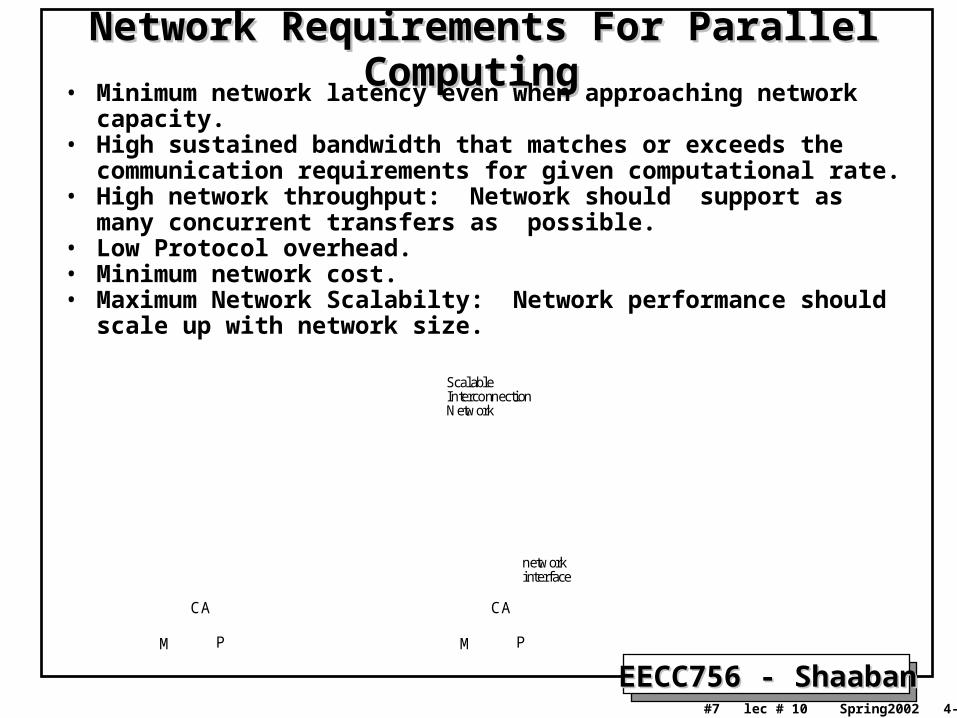
Network Requirements For Parallel ComputingNetwork Requirements For Parallel Computing • Minimum network latency even when approaching network capacity.• High sustained bandwidth that matches or exceeds the communication
requirements for given computational rate.• High network throughput: Network should support as many
concurrent transfers as possible.• Low Protocol overhead.• Minimum network cost.• Maximum Network Scalabilty: Network performance should scale up
with network size.
M P
CA
M P
CA
networkinterface
ScalableInterconnectionNetwork
EECC756 - ShaabanEECC756 - Shaaban#8 lec # 10 Spring2002 4-23-2002
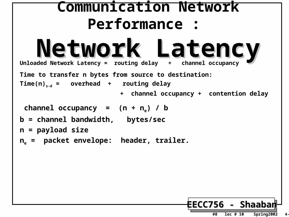
Communication Network Performance :
Network LatencyNetwork LatencyUnloaded Network Latency = routing delay + channel occupancy
Time to transfer n bytes from source to destination:
Time(n)s-d = overhead + routing delay
+ channel occupancy + contention delay
channel occupancy = (n + ne) / b
b = channel bandwidth, bytes/sec
n = payload size
ne = packet envelope: header, trailer.
EECC756 - ShaabanEECC756 - Shaaban#9 lec # 10 Spring2002 4-23-2002
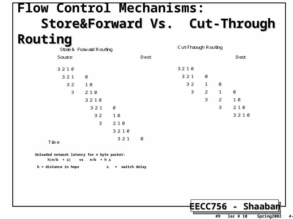
Flow Control Mechanisms: Store&Forward Vs. Cut-Through Routing Store&Forward Vs. Cut-Through Routing
Unloaded network latency for n byte packet:
h(n/b + ) vs n/b + h
h = distance in hops = switch delay
23 1 0
23 1 0
23 1 0
23 1 0
23 1 0
23 1 0
23 1 0
23 1 0
23 1 0
23 1 0
23 1 0
23 1
023
3 1 0
2 1 0
23 1 0
0
1
2
3
23 1 0Time
Store & Forward Routing Cut-Through Routing
Source Dest Dest
EECC756 - ShaabanEECC756 - Shaaban#10 lec # 10 Spring2002 4-23-2002
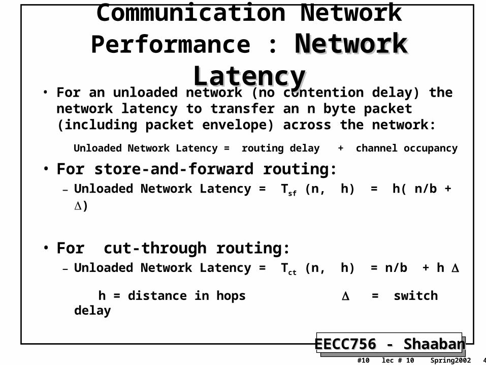
• For an unloaded network (no contention delay) the network latency to transfer an n byte packet (including packet envelope) across the network:
Unloaded Network Latency = routing delay + channel occupancy • For store-and-forward routing:
– Unloaded Network Latency = Tsf (n, h) = h( n/b + )
• For cut-through routing:– Unloaded Network Latency = Tct (n, h) = n/b + h
h = distance in hops = switch delay
Communication Network Performance : Network LatencyNetwork Latency
EECC756 - ShaabanEECC756 - Shaaban#11 lec # 10 Spring2002 4-23-2002
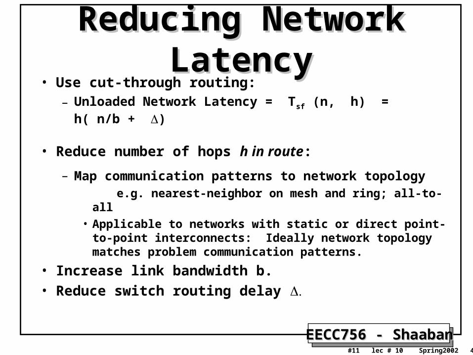
Reducing Network LatencyReducing Network Latency• Use cut-through routing:
– Unloaded Network Latency = Tsf (n, h) = h( n/b + )
• Reduce number of hops h in route:
– Map communication patterns to network topology e.g. nearest-neighbor on mesh and ring; all-to-all
• Applicable to networks with static or direct point-to-point interconnects: Ideally network topology matches problem communication patterns.
• Increase link bandwidth b.
• Reduce switch routing delay
EECC756 - ShaabanEECC756 - Shaaban#12 lec # 10 Spring2002 4-23-2002
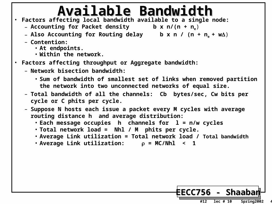
Available BandwidthAvailable Bandwidth• Factors affecting local bandwidth available to a single node:
– Accounting for Packet density b x n/(n + ne)– Also Accounting for Routing delay b x n / (n + ne + w)– Contention:
• At endpoints.• Within the network.
• Factors affecting throughput or Aggregate bandwidth:– Network bisection bandwidth:
• Sum of bandwidth of smallest set of links when removed partition the network into two unconnected networks of equal size.
– Total bandwidth of all the channels: Cb bytes/sec, Cw bits per cycle or C phits per cycle.
– Suppose N hosts each issue a packet every M cycles with average routing distance h and average distribution:
• Each message occupies h channels for l = n/w cycles • Total network load = Nhl / M phits per cycle.• Average Link utilization = Total network load / Total bandwidth • Average Link utilization: = MC/Nhl < 1
EECC756 - ShaabanEECC756 - Shaaban#13 lec # 10 Spring2002 4-23-2002
• Two packets trying to use the same link at same time.– May be caused by limited available buffering.– Possible resolutions:
• Increased buffer space. • Drop one or more packets.• Use an alternative route (requires an adaptive routing algorithm or a better static routing to
distribute load more evenly).
• Most networks used in parallel machines block in place – Link-level flow control.– Back pressure to the source to slow down flow of data.
• Closed system: Offered load depends on delivered.
Network Performance Factors: ContentionNetwork hot spots:Form in a network when a small number of network nodes/links handle a very large percentage of total networktraffic and become saturated.
Caused by communication load imbalance creating a high level of contention at these few nodes/links.
EECC756 - ShaabanEECC756 - Shaaban#14 lec # 10 Spring2002 4-23-2002
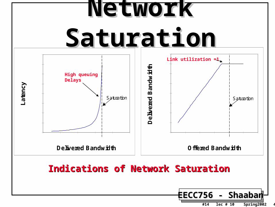
Network SaturationNetwork Saturation
0
10
20
30
40
50
60
70
80
0 0.2 0.4 0.6 0.8 1
Delivered Bandwidth
Lat
ency
Saturation
0
0.1
0.2
0.3
0.4
0.5
0.6
0.7
0.8
0 0.2 0.4 0.6 0.8 1 1.2
Offered BandwidthD
eliv
ered
Ban
dw
idth
Saturation
Indications of Network SaturationIndications of Network Saturation
High queuing Delays
Link utilization =1
EECC756 - ShaabanEECC756 - Shaaban#15 lec # 10 Spring2002 4-23-2002
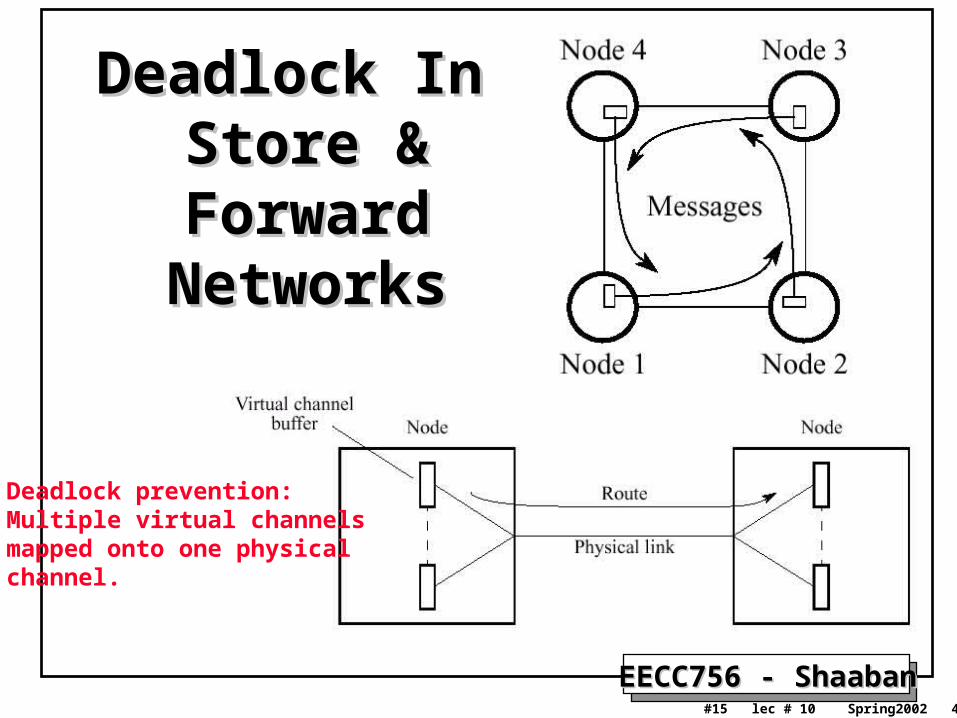
Deadlock In Deadlock In Store & Forward Store & Forward
NetworksNetworks
Deadlock prevention:Multiple virtual channels mapped onto one physical channel.
EECC756 - ShaabanEECC756 - Shaaban#16 lec # 10 Spring2002 4-23-2002
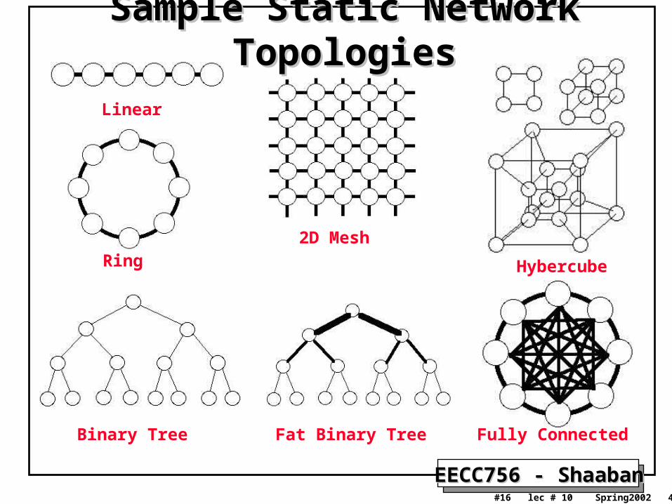
Sample Static Network TopologiesSample Static Network Topologies
Linear
Ring2D Mesh
Hybercube
Binary Tree Fat Binary Tree Fully Connected
EECC756 - ShaabanEECC756 - Shaaban#17 lec # 10 Spring2002 4-23-2002
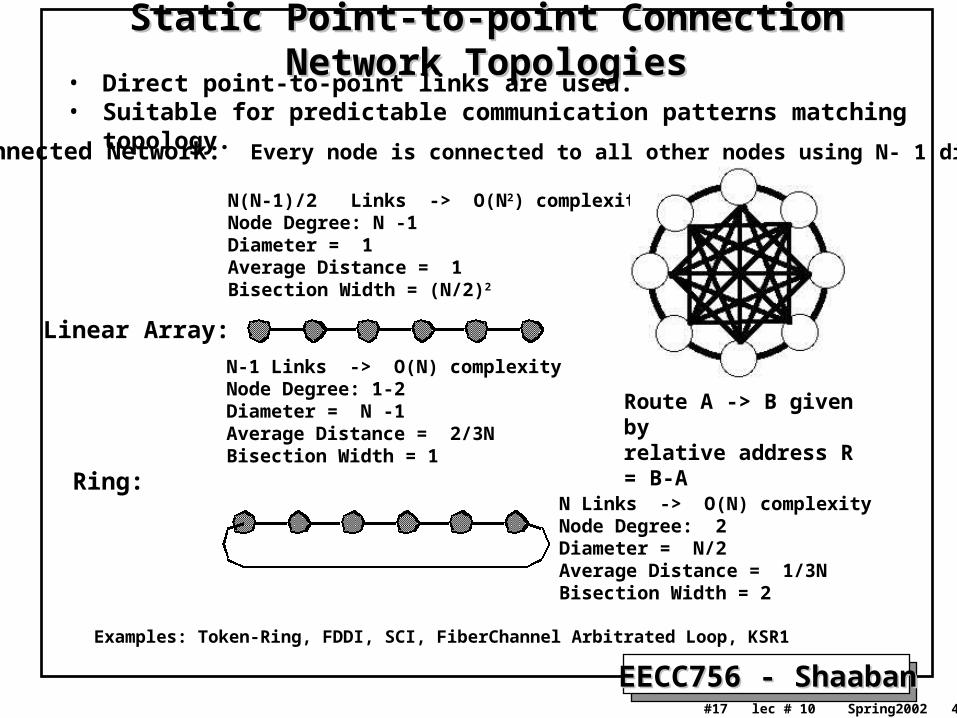
Static Point-to-point Connection Network TopologiesStatic Point-to-point Connection Network Topologies• Direct point-to-point links are used.• Suitable for predictable communication patterns matching topology.
Linear Array:
Ring:
Examples: Token-Ring, FDDI, SCI, FiberChannel Arbitrated Loop, KSR1
Route A -> B given by relative address R = B-A
N-1 Links -> O(N) complexityNode Degree: 1-2Diameter = N -1Average Distance = 2/3NBisection Width = 1
N Links -> O(N) complexityNode Degree: 2Diameter = N/2Average Distance = 1/3NBisection Width = 2
Fully Connected Network: Every node is connected to all other nodes using N- 1 direct links
N(N-1)/2 Links -> O(N2) complexityNode Degree: N -1 Diameter = 1Average Distance = 1Bisection Width = (N/2)2
EECC756 - ShaabanEECC756 - Shaaban#18 lec # 10 Spring2002 4-23-2002
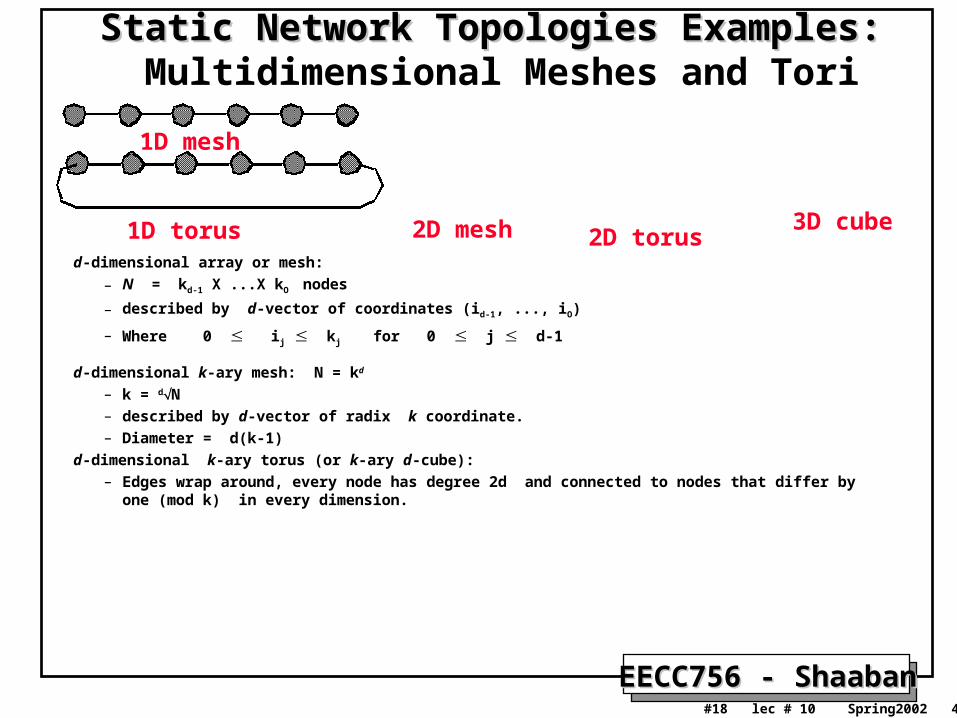
Static Network Topologies Examples:Static Network Topologies Examples: Multidimensional Meshes and Tori
3D cube2D mesh 2D torusd-dimensional array or mesh:
– N = kd-1 X ...X kO nodes
– described by d-vector of coordinates (id-1, ..., iO)
– Where 0 ij kj for 0 j d-1
d-dimensional k-ary mesh: N = kd
– k = dN– described by d-vector of radix k coordinate. – Diameter = d(k-1)
d-dimensional k-ary torus (or k-ary d-cube): – Edges wrap around, every node has degree 2d and connected to nodes that differ by one (mod k) in every
dimension.
1D torus
1D mesh
EECC756 - ShaabanEECC756 - Shaaban#19 lec # 10 Spring2002 4-23-2002
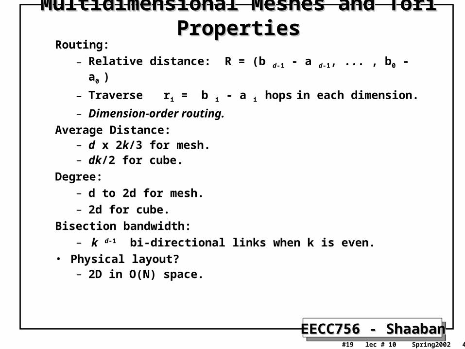
Multidimensional Meshes and Tori PropertiesMultidimensional Meshes and Tori PropertiesRouting:
– Relative distance: R = (b d-1 - a d-1, ... , b0 - a0 )
– Traverse ri = b i - a i hops in each dimension.
– Dimension-order routing.
Average Distance:– d x 2k/3 for mesh.– dk/2 for cube.
Degree:– d to 2d for mesh.– 2d for cube.
Bisection bandwidth:– k d-1 bi-directional links when k is even.
• Physical layout?– 2D in O(N) space.
EECC756 - ShaabanEECC756 - Shaaban#20 lec # 10 Spring2002 4-23-2002
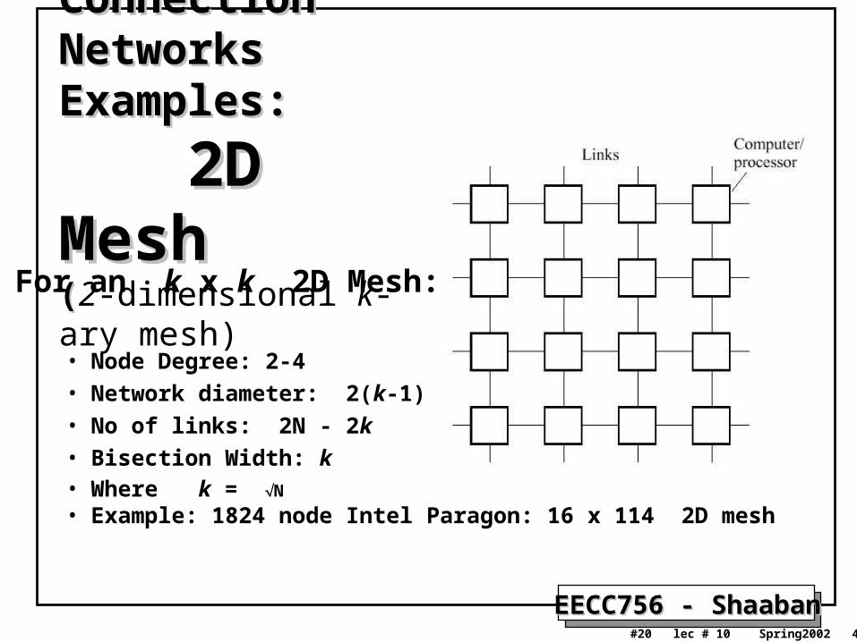
Static Connection Static Connection Networks Examples: Networks Examples:
2D Mesh2D Mesh((2-dimensional k-ary mesh)
• Node Degree: 2-4• Network diameter: 2(k-1)• No of links: 2N - 2k• Bisection Width: k• Where k = N
• Example: 1824 node Intel Paragon: 16 x 114 2D mesh
For an k x k 2D Mesh:
EECC756 - ShaabanEECC756 - Shaaban#21 lec # 10 Spring2002 4-23-2002
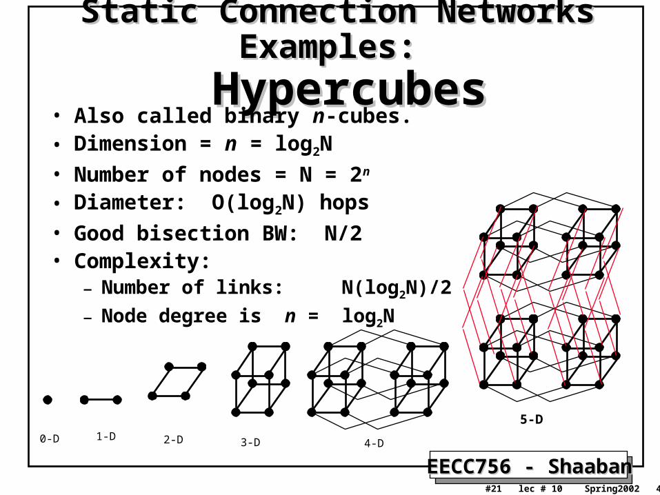
Static Connection Networks Examples: Static Connection Networks Examples:
HypercubesHypercubes• Also called binary n-cubes. • Dimension = n = log2N
• Number of nodes = N = 2n
• Diameter: O(log2N) hops
• Good bisection BW: N/2• Complexity:
– Number of links: N(log2N)/2
– Node degree is n = log2N
0-D 1-D 2-D 3-D 4-D
5-D
EECC756 - ShaabanEECC756 - Shaaban#22 lec # 10 Spring2002 4-23-2002
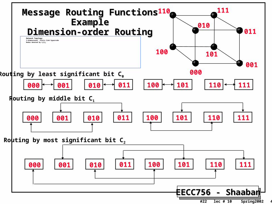
Message Routing Functions ExampleMessage Routing Functions ExampleDimension-order RoutingDimension-order Routing
Network Topology: 3-dimensional static-link hypercube Nodes denoted by C2C1C0
101
010
111
011
100
110
000001
000 001 010 011 100 101 110 111
Routing by least significant bit C0
000 001 010 011 100 101 110 111
Routing by middle bit C1
000 001 010 011 100 101 110 111
Routing by most significant bit C2
EECC756 - ShaabanEECC756 - Shaaban#23 lec # 10 Spring2002 4-23-2002
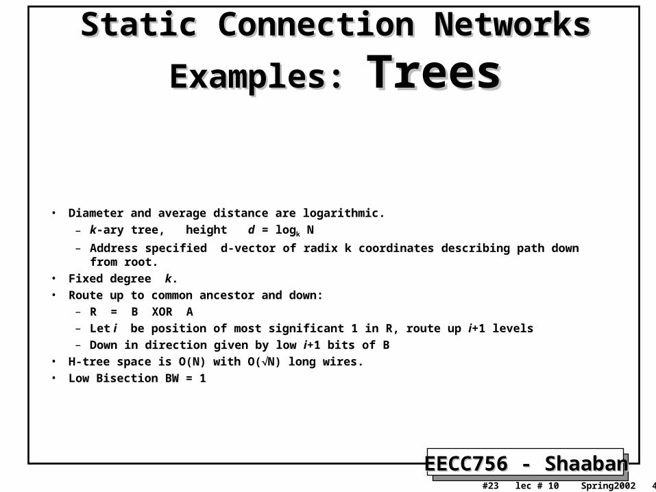
Static Connection Networks Examples: Static Connection Networks Examples:
TreesTrees
• Diameter and average distance are logarithmic.
– k-ary tree, height d = logk N
– Address specified d-vector of radix k coordinates describing path down from root.
• Fixed degree k.
• Route up to common ancestor and down:
– R = B XOR A
– Let i be position of most significant 1 in R, route up i+1 levels
– Down in direction given by low i+1 bits of B
• H-tree space is O(N) with O(N) long wires.
• Low Bisection BW = 1
EECC756 - ShaabanEECC756 - Shaaban#24 lec # 10 Spring2002 4-23-2002
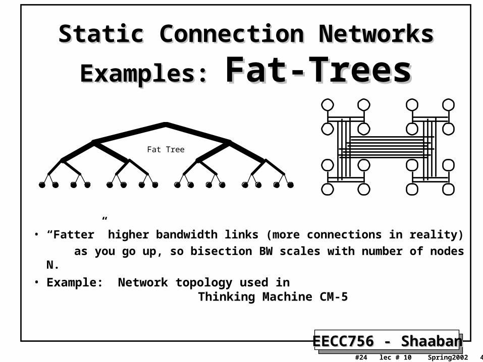
Static Connection Networks Examples: Static Connection Networks Examples:
Fat-TreesFat-Trees
Fat Tree
• “Fatter” higher bandwidth links (more connections in reality)
as you go up, so bisection BW scales with number of nodes N.
• Example: Network topology used in Thinking Machine CM-5
EECC756 - ShaabanEECC756 - Shaaban#25 lec # 10 Spring2002 4-23-2002
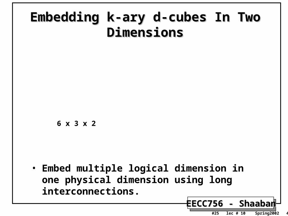
Embedding k-ary d-cubes In Two DimensionsEmbedding k-ary d-cubes In Two Dimensions
• Embed multiple logical dimension in one physical dimension using long interconnections.
6 x 3 x 2
EECC756 - ShaabanEECC756 - Shaaban#26 lec # 10 Spring2002 4-23-2002
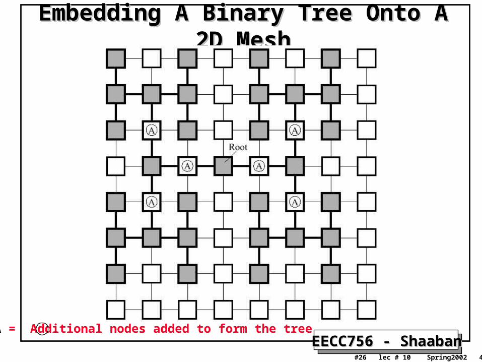
Embedding A Binary Tree Onto A 2D MeshEmbedding A Binary Tree Onto A 2D Mesh
A = Additional nodes added to form the tree
EECC756 - ShaabanEECC756 - Shaaban#27 lec # 10 Spring2002 4-23-2002
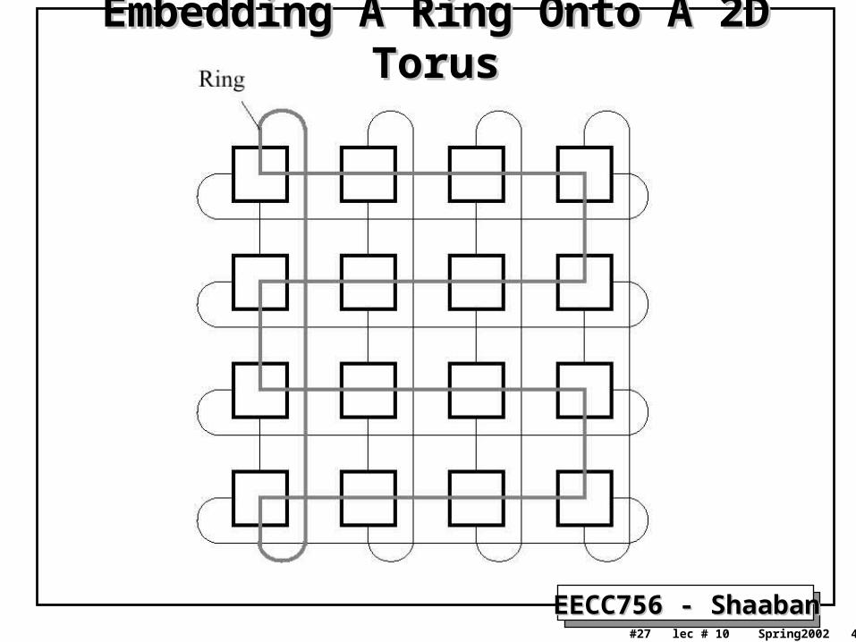
Embedding A Ring Onto A 2D TorusEmbedding A Ring Onto A 2D Torus
EECC756 - ShaabanEECC756 - Shaaban#28 lec # 10 Spring2002 4-23-2002
Dynamic Connection NetworksDynamic Connection Networks
• Switches are usually used to implement connection paths or virtual circuits between nodes instead of fixed point-to-point connections.
• Dynamic connections are established based on communication demands.
• Such networks include: – Bus systems.– Multi-stage Interconnection Networks (MINs):
• Omega Network.
• Baseline Network
• Butterfly Network, etc.
– Crossbar switch networks.
EECC756 - ShaabanEECC756 - Shaaban#29 lec # 10 Spring2002 4-23-2002
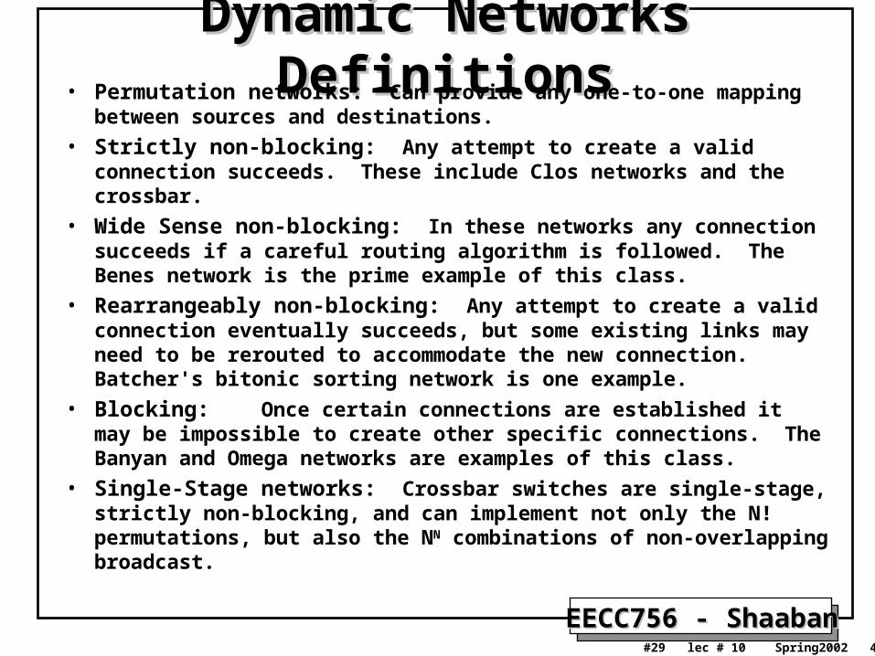
Dynamic Networks DefinitionsDynamic Networks Definitions• Permutation networks: Can provide any one-to-one mapping between
sources and destinations.
• Strictly non-blocking: Any attempt to create a valid connection succeeds. These include Clos networks and the crossbar.
• Wide Sense non-blocking: In these networks any connection succeeds if a careful routing algorithm is followed. The Benes network is the prime example of this class.
• Rearrangeably non-blocking: Any attempt to create a valid connection eventually succeeds, but some existing links may need to be rerouted to accommodate the new connection. Batcher's bitonic sorting network is one example.
• Blocking: Once certain connections are established it may be impossible to create other specific connections. The Banyan and Omega networks are examples of this class.
• Single-Stage networks: Crossbar switches are single-stage, strictly non-blocking, and can implement not only the N! permutations, but also the NN combinations of non-overlapping broadcast.
EECC756 - ShaabanEECC756 - Shaaban#30 lec # 10 Spring2002 4-23-2002
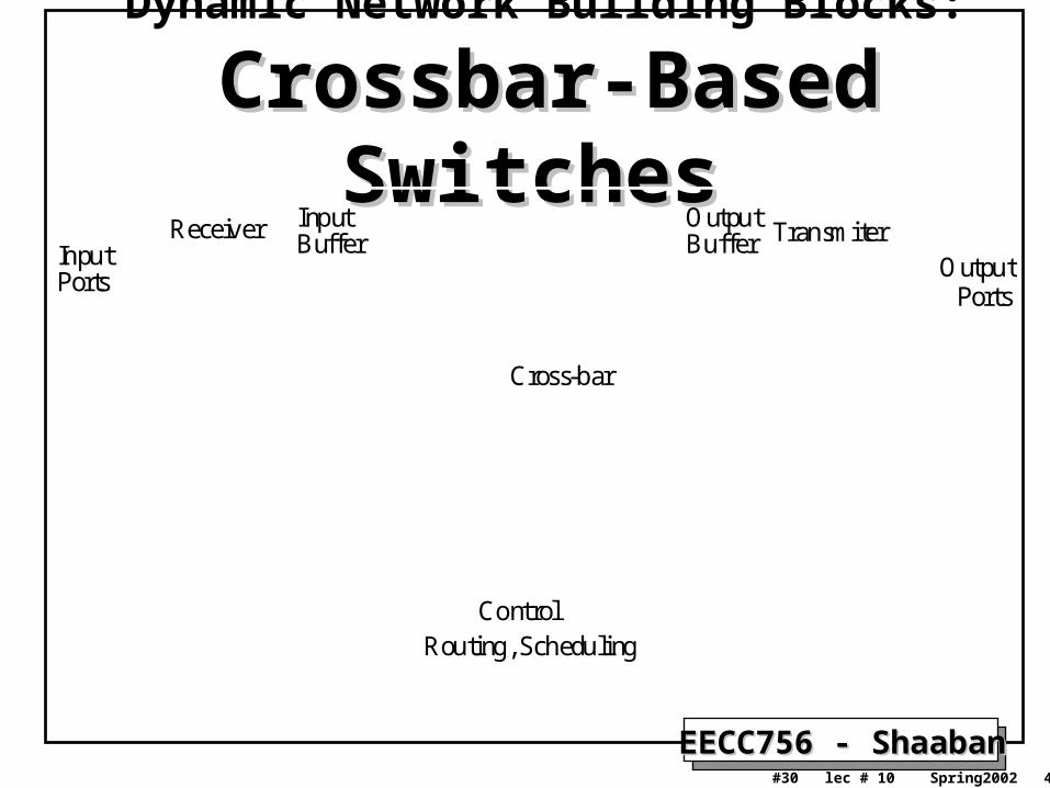
Dynamic Network Building Blocks:
Crossbar-Based SwitchesCrossbar-Based Switches
Cross-bar
InputBuffer
Control
OutputPorts
Input Receiver Transmiter
Ports
Routing, Scheduling
OutputBuffer
EECC756 - ShaabanEECC756 - Shaaban#31 lec # 10 Spring2002 4-23-2002
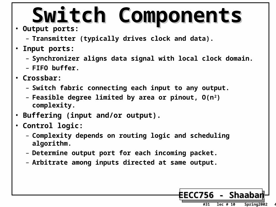
Switch ComponentsSwitch Components• Output ports:
– Transmitter (typically drives clock and data).
• Input ports:– Synchronizer aligns data signal with local clock domain.– FIFO buffer.
• Crossbar:– Switch fabric connecting each input to any output.– Feasible degree limited by area or pinout, O(n2) complexity.
• Buffering (input and/or output).• Control logic:
– Complexity depends on routing logic and scheduling algorithm.– Determine output port for each incoming packet.– Arbitrate among inputs directed at same output.
EECC756 - ShaabanEECC756 - Shaaban#32 lec # 10 Spring2002 4-23-2002
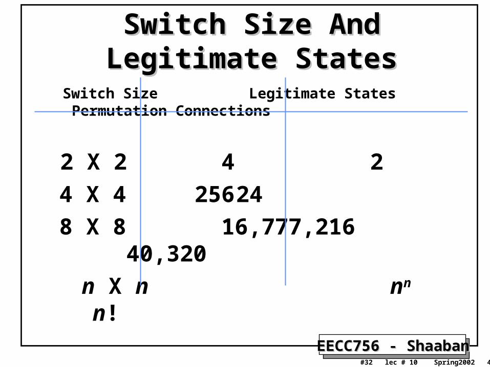
Switch Size And Legitimate StatesSwitch Size And Legitimate States
Switch Size Legitimate States Permutation Connections
2 X 2 4 2
4 X 4 256 24
8 X 8 16,777,216 40,320
n X n nn n!
EECC756 - ShaabanEECC756 - Shaaban#33 lec # 10 Spring2002 4-23-2002
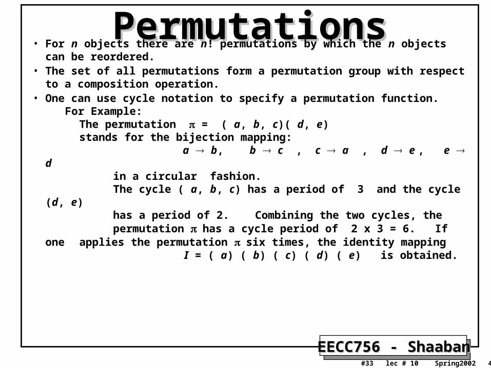
PermutationsPermutations• For n objects there are n! permutations by which the n objects can be
reordered. • The set of all permutations form a permutation group with respect to a
composition operation. • One can use cycle notation to specify a permutation function. For Example: The permutation = ( a, b, c)( d, e) stands for the bijection mapping: a b, b c , c a , d e , e d in a circular fashion. The cycle ( a, b, c) has a period of 3 and the cycle (d, e) has a period of 2. Combining the two cycles, the permutation has a cycle period of 2 x 3 = 6. If one
applies the permutation six times, the identity mapping I = ( a) ( b) ( c) ( d) ( e) is obtained.
EECC756 - ShaabanEECC756 - Shaaban#34 lec # 10 Spring2002 4-23-2002
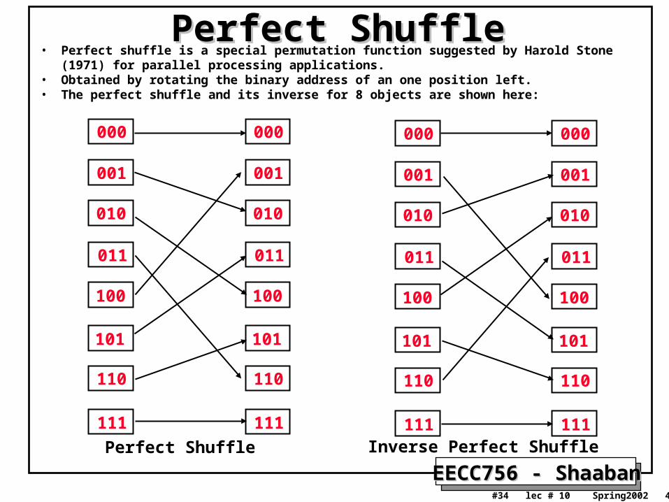
Perfect ShufflePerfect Shuffle• Perfect shuffle is a special permutation function suggested by Harold Stone (1971) for parallel
processing applications. • Obtained by rotating the binary address of an one position left.• The perfect shuffle and its inverse for 8 objects are shown here:
000
001
010
011
100
101
110
111
000
001
010
011
100
101
110
111
000
001
010
011
100
101
110
111
000
001
010
011
100
101
110
111Perfect Shuffle Inverse Perfect Shuffle
EECC756 - ShaabanEECC756 - Shaaban#35 lec # 10 Spring2002 4-23-2002
• In the Omega network, perfect shuffle is used as an inter-stage connection pattern for all log2N stages.
• Routing is simply a matter of using the destination's address bits to set switches at each stage.
• The Omega network is a single-path network: There is just one path between an input and an output.
• It is equivalent to the Banyan, Staran Flip Network, Shuffle Exchange Network, and many others that have been proposed.
• The Omega can only implement NN/2 of the N! permutations between inputs and outputs, so it is possible to have permutations that cannot be provided (i.e. paths that can be blocked). – For N = 8, there are 84/8! = 4096/40320 = 0.1016 = 10.16% of the
permutations that can be implemented.
• It can take log2N passes of reconfiguration to provide all links. Because there are log2 N stages, the worst case time to provide all desired connections can be (log2N)2.
Multi-Stage Networks: Multi-Stage Networks: The Omega NetworkThe Omega Network
EECC756 - ShaabanEECC756 - Shaaban#36 lec # 10 Spring2002 4-23-2002
Multi-Stage Networks: Multi-Stage Networks: The Omega NetworkThe Omega Network
Fig 2.24 page 92
Kai Hwang ref.
See handout
EECC756 - ShaabanEECC756 - Shaaban#37 lec # 10 Spring2002 4-23-2002
MINs Example: Baseline NetworkMINs Example: Baseline Network
Fig 2.25 page 93
Kai Hwang ref.
See handout
EECC756 - ShaabanEECC756 - Shaaban#38 lec # 10 Spring2002 4-23-2002
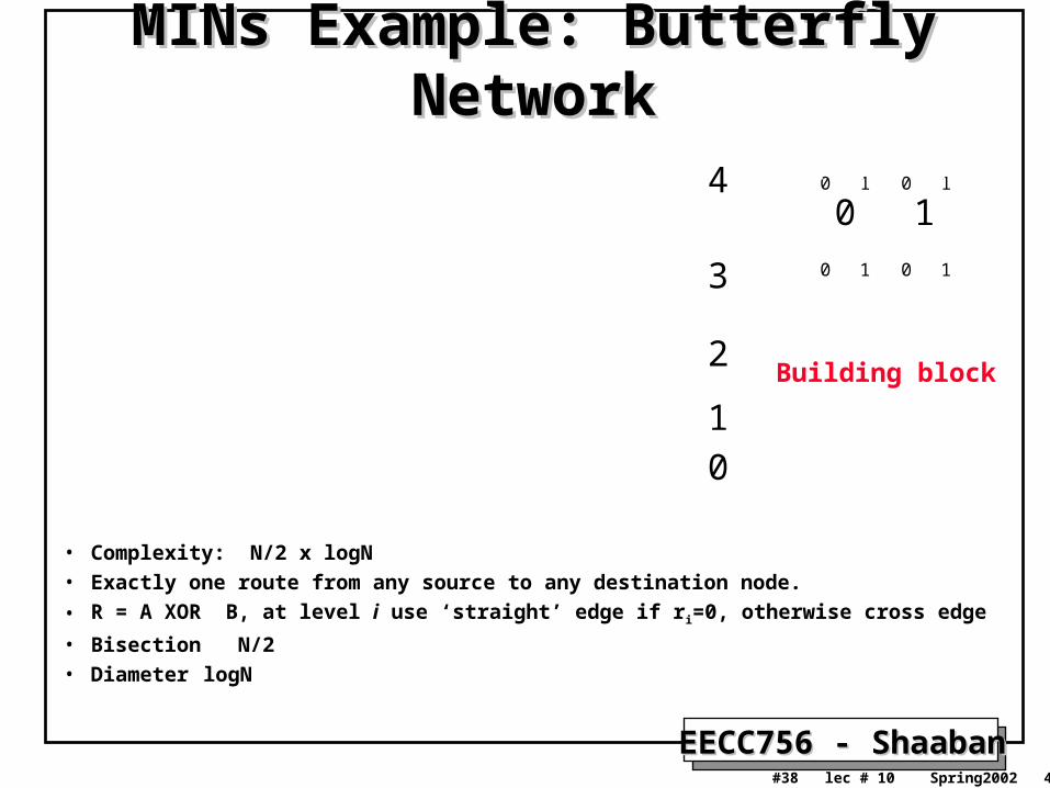
MINs Example: Butterfly NetworkMINs Example: Butterfly Network
• Complexity: N/2 x logN
• Exactly one route from any source to any destination node.
• R = A XOR B, at level i use ‘straight’ edge if ri=0, otherwise cross edge
• Bisection N/2
• Diameter logN
0
1
2
3
4
0 1 0 1
0 1 0 1
0 1
Building block
EECC756 - ShaabanEECC756 - Shaaban#39 lec # 10 Spring2002 4-23-2002
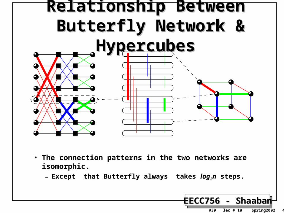
Relationship BetweenRelationship Between Butterfly Network & Hypercubes Butterfly Network & Hypercubes
• The connection patterns in the two networks are isomorphic.– Except that Butterfly always takes log2n steps.
EECC756 - ShaabanEECC756 - Shaaban#40 lec # 10 Spring2002 4-23-2002
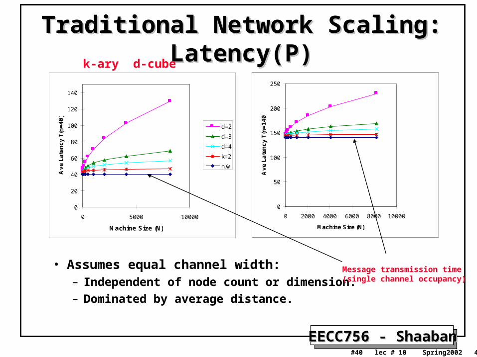
Traditional Network Scaling: Latency(P)Traditional Network Scaling: Latency(P)
• Assumes equal channel width:– Independent of node count or dimension.– Dominated by average distance.
0
20
40
60
80
100
120
140
0 5000 10000
Machine Size (N)
Ave L
ate
ncy T
(n=40)
d=2
d=3
d=4
k=2
n/w
0
50
100
150
200
250
0 2000 4000 6000 8000 10000
Machine Size (N)
Ave L
ate
ncy T
(n=140)
k-ary d-cube
Message transmission time(single channel occupancy)
EECC756 - ShaabanEECC756 - Shaaban#41 lec # 10 Spring2002 4-23-2002
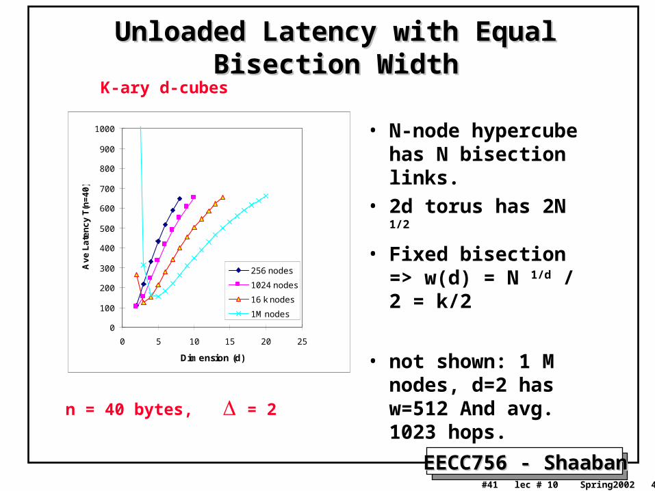
Unloaded Latency with Equal Bisection WidthUnloaded Latency with Equal Bisection Width
• N-node hypercube has N bisection links.
• 2d torus has 2N 1/2
• Fixed bisection => w(d) = N 1/d / 2 = k/2
• not shown: 1 M nodes, d=2 has w=512 And avg. 1023 hops.
0
100
200
300
400
500
600
700
800
900
1000
0 5 10 15 20 25
Dimension (d)
Ave L
ate
ncy T
(n=40)
256 nodes
1024 nodes
16 k nodes
1M nodes
K-ary d-cubes
n = 40 bytes, = 2
EECC756 - ShaabanEECC756 - Shaaban#42 lec # 10 Spring2002 4-23-2002
Summary of Static Network Summary of Static Network CharacteristicsCharacteristics
Table 2.2 page 88
Kai Hwang ref.
See handout
EECC756 - ShaabanEECC756 - Shaaban#43 lec # 10 Spring2002 4-23-2002
Summary of Dynamic Network Summary of Dynamic Network CharacteristicsCharacteristics
Table 2.4 page 95
Kai Hwang ref.
See handout
EECC756 - ShaabanEECC756 - Shaaban#44 lec # 10 Spring2002 4-23-2002
Example Networks: Cray MPPsExample Networks: Cray MPPs• T3D: Short, Wide, Synchronous (300 MB/s).
– 3D bidirectional torus up to 1024 nodes, dimension order, virtual cut-through, packet switched routing.
– 24 bits: 16 data, 4 control, 4 reverse direction flow control– Single 150 MHz clock (including processor).– flit = phit = 16 bits.– Two control bits identify flit type (idle and framing).
• No-info, routing tag, packet, end-of-packet.
• T3E: long, wide, asynchronous (500 MB/s)– 14 bits, 375 MHz– flit = 5 phits = 70 bits
• 64 bits data + 6 control
– Switches operate at 75 MHz.– Framed into 1-word and 8-word read/write request packets.
EECC756 - ShaabanEECC756 - Shaaban#45 lec # 10 Spring2002 4-23-2002
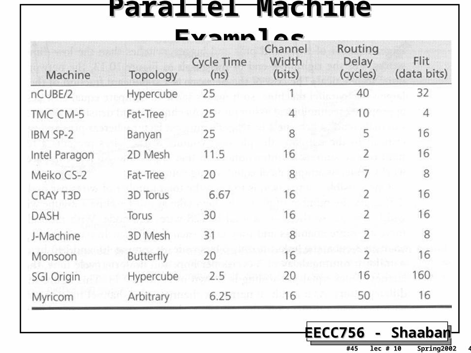
Parallel Machine ExamplesParallel Machine Examples