Embed Size (px)
Citation preview

1
1SMEECE 251, Set 3
EECE251
Circuit Analysis I
Set 3: Additional Analysis Techniques and Circuit Theorems
Shahriar MirabbasiDepartment of Electrical and Computer Engineering
University of British [email protected]
2SM
Reading Material
• Chapter 5 of the textbook
– Section 5.1: Linearity
– Section 5.2: Superposition
– Section 5.3: Source Transformation, and Thévenin’s andNorton’s Theorems
– Section 5.4: Maximum Power Transfer
• Reading assignment:
– Review Section 5.5: Application Examples
EECE 251, Set 3
2
3SMEECE 251, Set 3
Linearity
• Simply put, a linear circuit (or in general a linear system) is acircuit (system) whose output is linearly related (or directlyproportional) to its input.
• A system is linear if and only if it has these two properties:
1. If the input of the system is multiplied by a constant then theoutput is also multiplied by a same constant (homogeneity).
2. The output of the system to a sum of inputs is the sum of theoutputs to each input applied separately (additivity).
Linear
Systemx y
Linear
Systemax ay
Linear
System
x1 y1 Linear
System
x2 y2 Linear
System
x1+x2 y1+y2
4SM
Linearity
• General definition:
• For all α and β
EECE 251, Set 3
Linear
System
x1 y1 Linear
System
x2 y2
Linear
System
αx1+βx2 αy1+βy2
3
5SMEECE 251, Set 3
Linearity
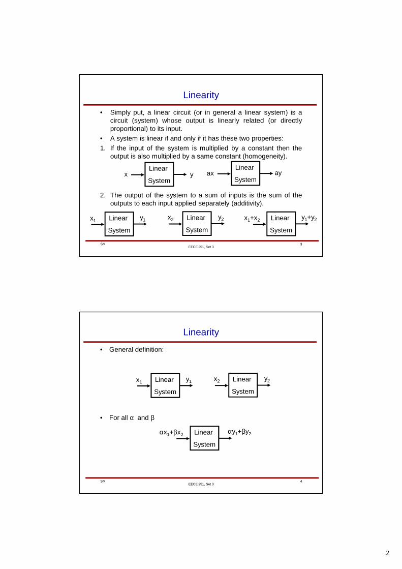
• In circuit theory, the inputs of a circuit are usually theindependent voltage or current sources and the outputs are thevoltages or currents of some elements of the circuit.
• Example: Let’s consider a single resistor as a system. Asshown below, the input of this system is an independent currentsource and the output is the voltage drop across the resistor. Isthis system linear?
I R V
+
-
6SMEECE 251, Set 3
Linearity Theorem
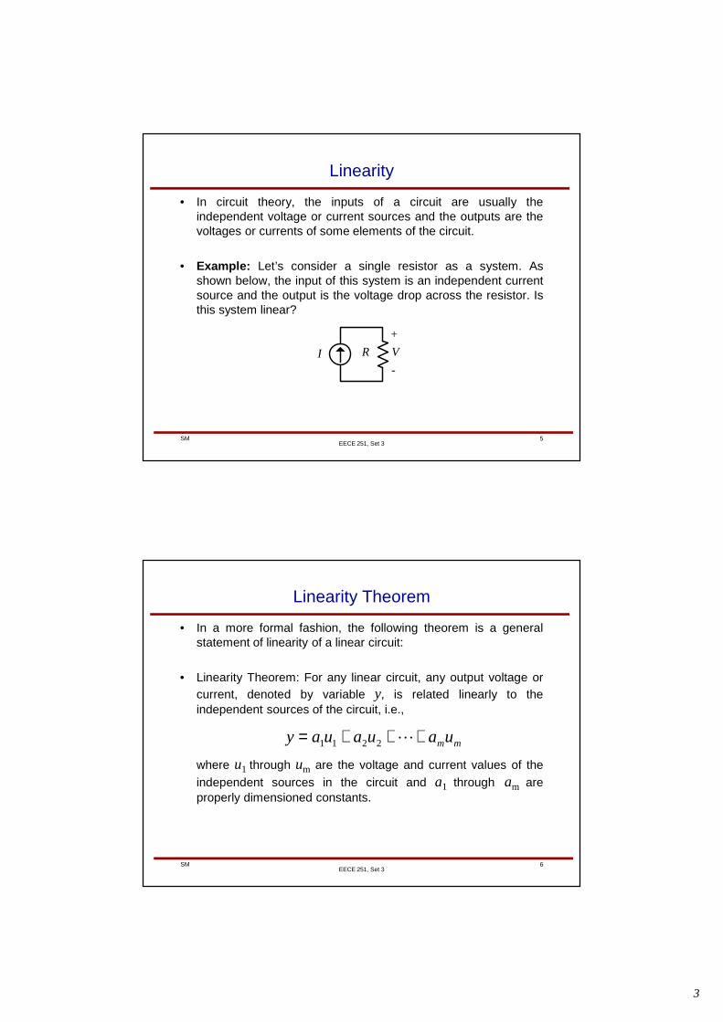
• In a more formal fashion, the following theorem is a generalstatement of linearity of a linear circuit:
• Linearity Theorem: For any linear circuit, any output voltage orcurrent, denoted by variable y, is related linearly to theindependent sources of the circuit, i.e.,
where u1 through um are the voltage and current values of the
independent sources in the circuit and a1 through am areproperly dimensioned constants.
mmuauauay +++= L2211
4
7SMEECE 251, Set 3
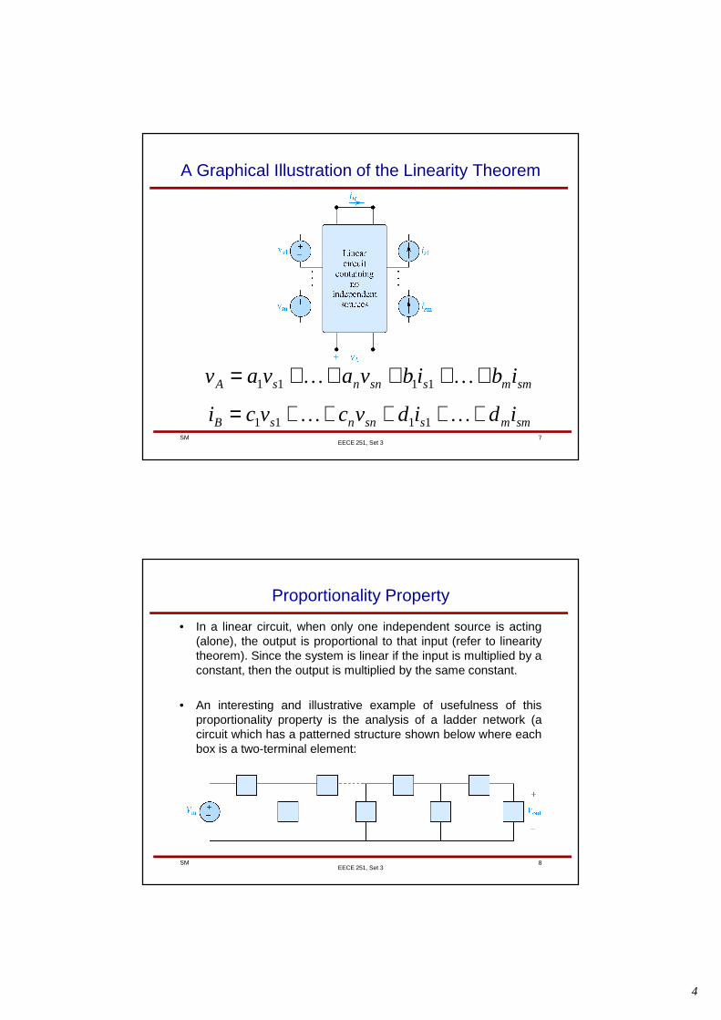
A Graphical Illustration of the Linearity Theorem
smmssnnsA ibibvavav +++++= KK 1111
smmssnnsB ididvcvci +++++= KK 1111
8SMEECE 251, Set 3
Proportionality Property
• In a linear circuit, when only one independent source is acting(alone), the output is proportional to that input (refer to linearitytheorem). Since the system is linear if the input is multiplied by aconstant, then the output is multiplied by the same constant.
• An interesting and illustrative example of usefulness of thisproportionality property is the analysis of a ladder network (acircuit which has a patterned structure shown below where eachbox is a two-terminal element:
5
9SMEECE 251, Set 3
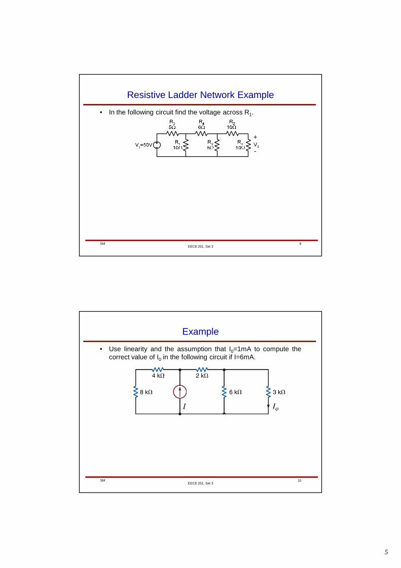
Resistive Ladder Network Example
• In the following circuit find the voltage across R1.
+
-V1
10SM
Example
• Use linearity and the assumption that I0=1mA to compute thecorrect value of I0 in the following circuit if I=6mA.
EECE 251, Set 3

6
11SMEECE 251, Set 3
Superposition Property
• In a linear circuit containing more than one independent source,the voltage across or current through any element is thealgebraic sum of the of the voltages across or currents throughthat element due to each independent source acting alone, withthe remaining independent sources deactivated, i.e., theirvalues set to zero.
• Steps for applying superposition principle:
1. Turn off all independent sources except one source. Find thedesired voltage or current due to that source.
2. Repeat the previous step for each of the independent sources.
3. Find the total desired voltage or current by algebraically addingthe contributions due to each of the independent sources
12SMEECE 251, Set 3
Example
• Using superposition principle find I in the following circuit:
7
13SMEECE 251, Set 3
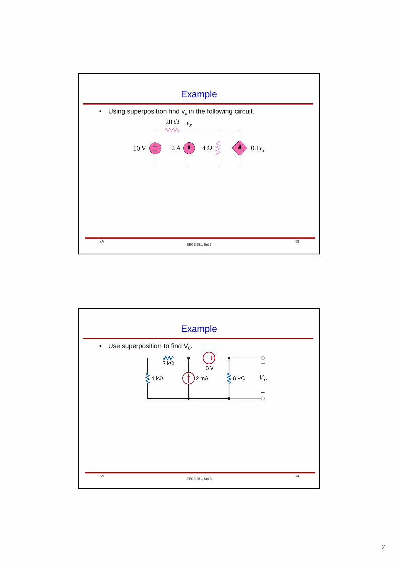
Example
• Using superposition find vx in the following circuit.
-0.1vx2A
14SM
Example
• Use superposition to find V0.
EECE 251, Set 3

8
15SMEECE 251, Set 3
Source Transformation
• Source transformation refers to the process of replacing avoltage source in series with a resistor R with a current sourcein parallel with a resistor (with the same resistance value as R)and vice versa.
• In many circuits source transformation can simplify the analysis.
• Recall that a pair of two terminal networks (circuits) areequivalent if they have the same terminal v-i characteristics.
16SMEECE 251, Set 3
Source Transformation Theorem
• For independent sources (Note the direction of the current of thecurrent source):
• For Dependent sources:
9
17SMEECE 251, Set 3
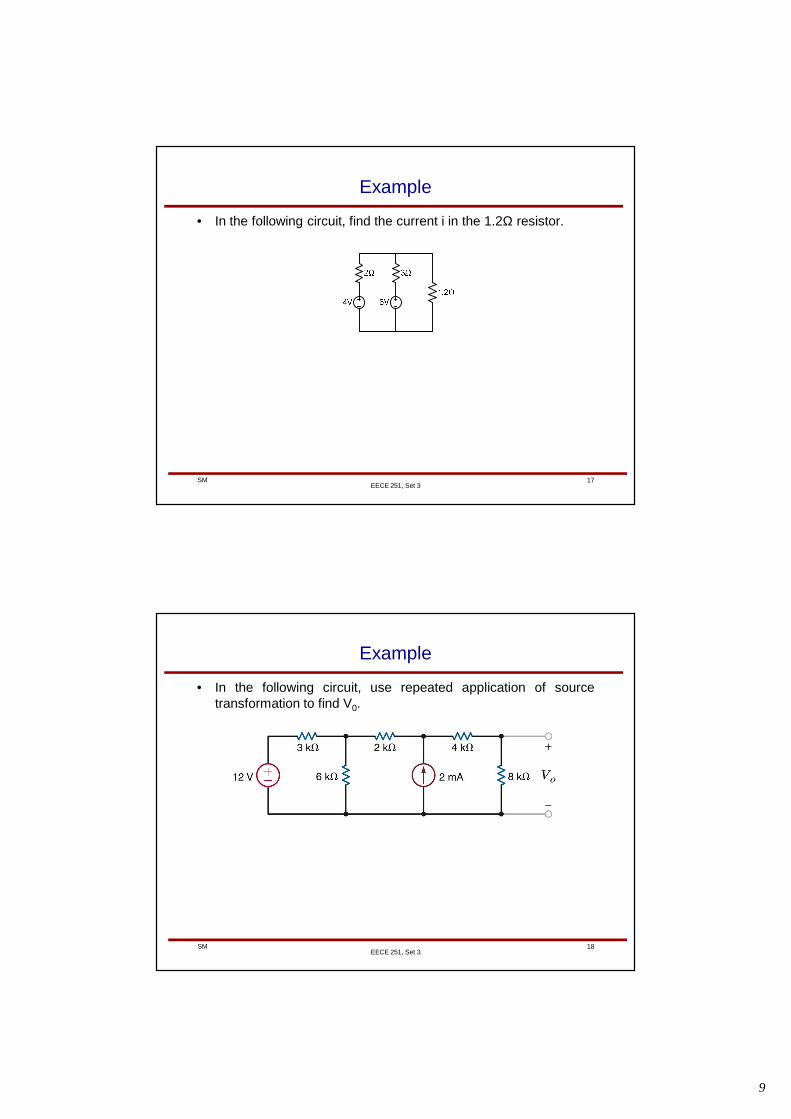
Example
• In the following circuit, find the current i in the 1.2Ω resistor.
18SM
Example
• In the following circuit, use repeated application of sourcetransformation to find V0.
EECE 251, Set 3

10
19SMEECE 251, Set 3
Example
• In the following circuit, use source transformation to find vx.
20SM
Notes
EECE 251, Set 3

11
21SMEECE 251, Set 3
Thévenin’s Theorem
• In practice, it often happens that a particular element (or block)in a circuit is variable (this variable block is usually called load)and the rest of the circuit elements are fixed.
• As an example think of different load speakers with differentinternal resistance that can be connected to an stereo amplifier.
• To avoid analyzing the whole circuit each time the variableelement changes, in 1883, Leon Charles Thévenin (1857-1926),a French telegraph engineer came up with the interesting ideaof replacing a complicated linear circuit by an equivalent circuitconsisting of an independent voltage source in series with aresistor.
22SMEECE 251, Set 3
Thévenin’s Theorem
• Theorem:
• Formal proof of the Thévenin’s theorem

12
23SMEECE 251, Set 3
Thévenin’s Theorem
• The value of voltage source in the Thévenin equivalent circuit isthe open-circuit voltage at the terminal of the circuit and RTH isthe equivalent resistance seen at the terminal when theindependent sources inside the circuit are turned off.
24SM
Ways to Find Thévenin Equivalent of a circuit
• Approach discussed on previous page, that is Vth=Voc and tofind Rth turn off the independent sources and find the equivalentresistance seen at the load terminal. This approach may betricky when the circuit include dependent sources.
• Another approach is to short-circuit the load terminal. Find theshort circuit current, Isc, and then Vth=Voc and Rth=Voc/Isc.
Can you prove that these equations are correct?
• UBC’s 1A/2A approach! (I would like to thank Dr. Luis Linaresfor explaining this elegant technique to me.)
EECE 251, Set 3
13
25SM
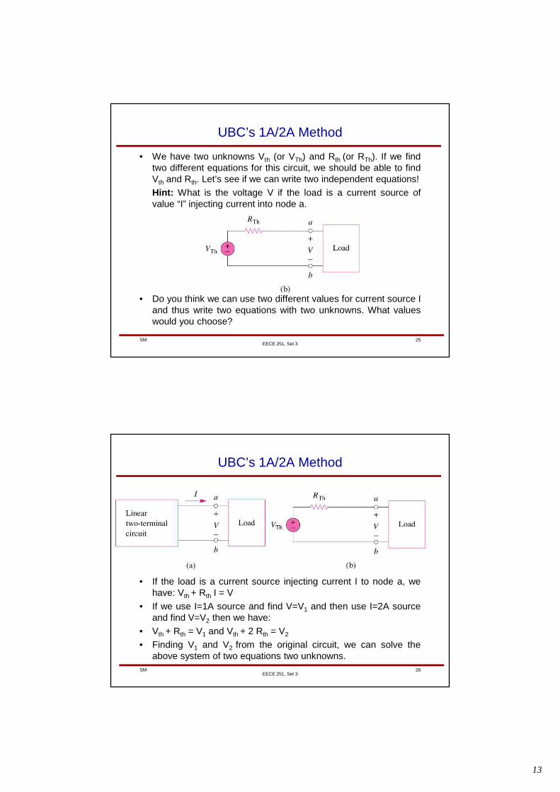
UBC’s 1A/2A Method
• We have two unknowns Vth (or VTh) and Rth (or RTh). If we findtwo different equations for this circuit, we should be able to findVth and Rth. Let’s see if we can write two independent equations!
Hint: What is the voltage V if the load is a current source ofvalue “I” injecting current into node a.
• Do you think we can use two different values for current source Iand thus write two equations with two unknowns. What valueswould you choose?
EECE 251, Set 3
26SM
UBC’s 1A/2A Method
• If the load is a current source injecting current I to node a, wehave: Vth + Rth I = V
• If we use I=1A source and find V=V1 and then use I=2A sourceand find V=V2 then we have:
• Vth + Rth = V1 and Vth + 2 Rth = V2
• Finding V1 and V2 from the original circuit, we can solve theabove system of two equations two unknowns.
EECE 251, Set 3
14
27SM
Notes
EECE 251, Set 3
28SMEECE 251, Set 3
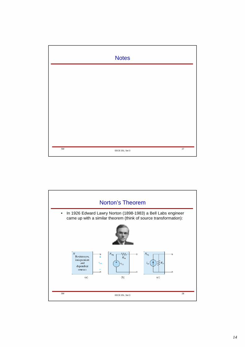
Norton’s Theorem
• In 1926 Edward Lawry Norton (1898-1983) a Bell Labs engineercame up with a similar theorem (think of source transformation):
15
29SMEECE 251, Set 3
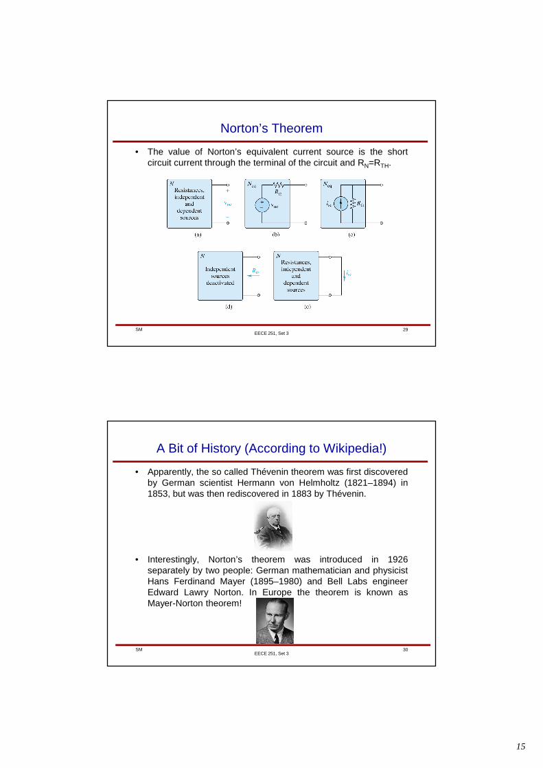
Norton’s Theorem
• The value of Norton’s equivalent current source is the shortcircuit current through the terminal of the circuit and RN=RTH.
30SM
A Bit of History (According to Wikipedia!)
• Apparently, the so called Thévenin theorem was first discoveredby German scientist Hermann von Helmholtz (1821–1894) in1853, but was then rediscovered in 1883 by Thévenin.
• Interestingly, Norton’s theorem was introduced in 1926separately by two people: German mathematician and physicistHans Ferdinand Mayer (1895–1980) and Bell Labs engineerEdward Lawry Norton. In Europe the theorem is known asMayer-Norton theorem!
EECE 251, Set 3

16
31SMEECE 251, Set 3
Example
• Use Thévenin’s theorem to find the equivalent circuit to the leftof the terminals a and b in the following circuit and then find I.Find Thévenin equivalent of the system using all threeapproaches that we have discussed.
32SM
Notes
EECE 251, Set 3
17
33SM
Notes
EECE 251, Set 3
34SM
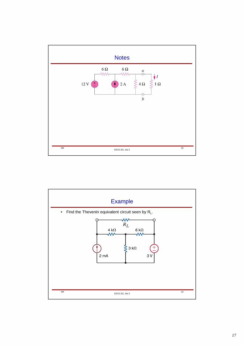
Example
• Find the Thevenin equivalent circuit seen by RL.
EECE 251, Set 3

18
35SMEECE 251, Set 3
36SMEECE 251, Set 3
Example
• Find the Thévenin equivalent of the following circuit:
• Can you guess what is Vth before even picking up your pencil tosolve this question?!

19
37SMEECE 251, Set 3
Example
• Find the Norton equivalent of the following circuit:
38SM
Example
• Find the Thévenin equivalent of the following circuit:
EECE 251, Set 3

20
39SMEECE 251, Set 3
Maximum Power Transfer
• In many practical circuits, it is desirable to provide maximumpower to the load.
LLTh
ThL R
RR
VRip
22
+==
40SMEECE 251, Set 3
Maximum Power Transfer
• Power delivered to the load as a function of RL:
• Maximum power is transferred to the load when the loadresistance equals the Thevenin resistance as seen from theload (that is, RL=RTh)
• Formal proof:

21
41SMEECE 251, Set 3
Example
• Find the value of RL for maximum power transfer in the followingcircuit. What is the maximum power?
42SM
• Find the value of RL to which the maximum power is transferredin the following circuit. What is the maximum power?
EECE 251, Set 3

22
43SM
Example
• Find the value of RL to which the maximum power is transferredin the following circuit. What is the maximum power?
EECE 251, Set 3
44SM
Notes
EECE 251, Set 3