Embed Size (px)
Citation preview
三 菱 マ テ リ ア ル 株 式 会 社MITSUBISHI MATERIALS CORPORATIONw w w . m m c . c o . j p / a d v / d e v
Copyright © 2017 MITSUBISHI MATERIALS CORPORATION Technical data Ver.3.01 / 9
三菱マテリアル株式会社電子材料事業カンパニー
電子デバイス事業部MITSUBISHI MATERIALS CORPORATION
ELECTRONIC MATERIALS & COMPONENTS COMPANYELECTRONIC COMPONENTS DIVISION
技術資料(第3版)サージアブソーバ
Technical data (Ver.3.0)Surge Absorber
三 菱 マ テ リ ア ル 株 式 会 社MITSUBISHI MATERIALS CORPORATIONw w w . m m c . c o . j p / a d v / d e v
Copyright © 2017 MITSUBISHI MATERIALS CORPORATION Technical data Ver.3.02 / 9
技術資料(第3版)Technical data (Ver.3.0)
もくじContents ページ
1.サージとは? ~サージ対策でお困りではありませんか?~ 3What is Surge?
2.誘導雷サージ 3Induced Surge
3.誘導雷サージの侵入経路 4Invasion of Induced Surge
4.サージアブソーバとは 4What is a Surge Absorber?
5.サージ防護デバイス 4SPD: Surge Protective Device
6.マイクロギャップ式サージアブソーバ 5Micro-gap Surge Absorber
7.続流について 5About Follow-On Current
8.放電管の V-I 特性 5V-I properties of gas discharge tubes
9.ホールドオーバとは 6What is Holdover?
10.ホールドオーバのメカニズム 6Mechanism of Holdover
11.AC 電源に対する続流とは 7Follow-on current from AC sources
12.技術コンサルタント ~立会試験サービス~ 8CONSULTING ~ Surge Test Service ~
三 菱 マ テ リ ア ル 株 式 会 社MITSUBISHI MATERIALS CORPORATIONw w w . m m c . c o . j p / a d v / d e v
Copyright © 2017 MITSUBISHI MATERIALS CORPORATION Technical data Ver.3.03 / 9
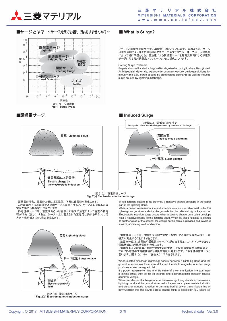
図1 サージの種類Fig.1 Surge Types
サージとは瞬間的に発生する異常電圧のことをいいます。 図のように、 サージは発生原因により様々に分類されますが、 三菱マテリアル (株) では、 回路設計において特に問題となる、 雷放電による誘導雷サージと静電気放電による静電気サージに対する対策部品/ソリューションをご提供しています。
Solving Surge ProblemsSurge is abnormal transient voltage and is categorized according to where it is originated.At Mitsubishi Materials, we provide countermeasure devices/solutions for circuitry and ESD surge caused by electrostatic discharge as well as induced surge caused by lightning discharge.
図 2 (b) 電磁誘導サージFig. 2(b) Electromagnetic induction surge
電磁誘導サージは、 雷雲と大地間で放電 (落雷) する時に大電流が流れ、 電磁界が発生することにより生じます。 落雷点の近くに送電線や通信線のケーブルが存在すると、 これがアンテナとなり電磁誘導により異常電圧が発生します。 雷雲間あるいは雷雲と大地で放電を起こす時、 近傍の送電線や通信線のケーブルに静電誘導や電磁誘導により異常電圧が発生します。 これを誘導雷サージと言います。 図 2 (a) (b) に発生メカニズムを示します。
When electric discharge (lightning) occurs between a lightning cloud and the ground, a severe electric current drifts and the electromagnetic induction surge produces an electromagnetic field.If a power transmission line and the cable of a communication line exist near a lighting strike, they act as an antenna and electromagnetic induction causes abnormal voltage.When an electric discharge occurs between lightning clouds or between a lightning cloud and the ground, abnormal voltage occurs by electrostatic induction and electromagnetic induction to the neighboring power transmission line or communication line. This is what is called Induced Surge as illustrated in fig.2 (a) and (b).
■誘導雷サージ
図 2 (a) 静電誘導サージFig. 2(a) Electrostatic induction surge
夏季雷の場合、 雷雲の上部には正電荷、 下部に負電荷が発生します。 この雷雲の下に送電線や通信線ケーブルが存在すると、 ケーブルの上にも正の電荷が集められ高電圧が発生します。 静電誘導サージは、 雷雲間あるいは雷雲と大地間の放電によって雷雲の負電荷が消失 (減少) すると、 ケーブル上に蓄えられた正電荷は拘束を解かれて両方向へ進行波となって進み発生します。
When lightning occurs in the summer, a negative charge develops in the upper part of the lightning cloud.When a power transmission line and a communication line cable exist under this lightning cloud, equilateral electric charges collect on the cable and high voltage occurs.Electrostatic induction surge occurs when a positive charge on a cable develops near a negative charge from a lightning cloud. When the cloud releases its charge to another cloud or the ground, the charge on the cable is released and travels in a wave, advancing in either direction.
■サージとは? ~サージ対策でお困りではありませんか?~ ■ What is Surge?
■ Induced Surge
三 菱 マ テ リ ア ル 株 式 会 社MITSUBISHI MATERIALS CORPORATIONw w w . m m c . c o . j p / a d v / d e v
Copyright © 2017 MITSUBISHI MATERIALS CORPORATION Technical data Ver.3.04 / 9
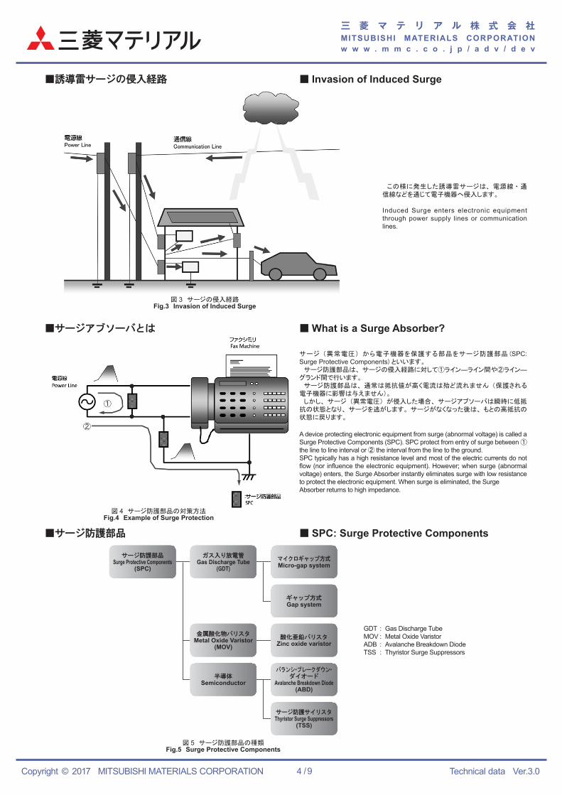
この様に発生した誘導雷サージは、 電源線 ・ 通信線などを通じて電子機器へ侵入します。
Induced Surge enters electronic equipment through power supply lines or communication lines.
図 4 サージ防護部品の対策方法Fig.4 Example of Surge Protection
図 5 サージ防護部品の種類Fig.5 Surge Protective Components
サージ (異常電圧) から電子機器を保護する部品をサージ防護部品 (SPC: Surge Protective Components) といいます。 サージ防護部品は、 サージの侵入経路に対して①ライン―ライン間や②ライン―グランド間で行います。 サージ防護部品は、 通常は抵抗値が高く電流は殆ど流れません (保護される電子機器に影響は与えません)。 しかし、 サージ (異常電圧) が侵入した場合、 サージアブソーバは瞬時に低抵抗の状態となり、 サージを逃がします。 サージがなくなった後は、 もとの高抵抗の状態に戻ります。
A device protecting electronic equipment from surge (abnormal voltage) is called a Surge Protective Components (SPC). SPC protect from entry of surge between ① the line to line interval or ② the interval from the line to the ground.SPC typically has a high resistance level and most of the electric currents do not flow (nor influence the electronic equipment). However; when surge (abnormal voltage) enters, the Surge Absorber instantly eliminates surge with low resistance to protect the electronic equipment. When surge is eliminated, the SurgeAbsorber returns to high impedance.
GDT : Gas Discharge TubeMOV : Metal Oxide VaristorADB : Avalanche Breakdown DiodeTSS : Thyristor Surge Suppressors
図 3 サージの侵入経路Fig.3 Invasion of Induced Surge
■誘導雷サージの侵入経路 ■ Invasion of Induced Surge
■ What is a Surge Absorber?
■ SPC: Surge Protective Components
■サージアブソーバとは
■サージ防護部品
サージ防護部品Surge Protective Components
(SPC)
ガス入り放電管Gas Discharge Tube
(GDT)マイクロギャップ方式Micro-gap system
ギャップ方式Gap system
酸化亜鉛バリスタZinc oxide varistor
バランシ・ブレークダウン・ダイオード
Avalanche Breakdown Diode(ABD)
サージ防護サイリスタThyristor Surge Suppressors
(TSS)
金属酸化物バリスタMetal Oxide Varistor
(MOV)
半導体Semiconductor
三 菱 マ テ リ ア ル 株 式 会 社MITSUBISHI MATERIALS CORPORATIONw w w . m m c . c o . j p / a d v / d e v
Copyright © 2017 MITSUBISHI MATERIALS CORPORATION Technical data Ver.3.05 / 9
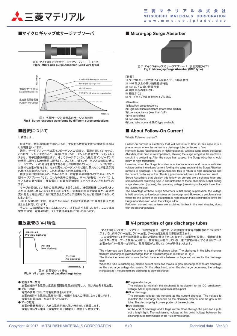
図 6 マイクロギャップ式サージアブソーバ (リードタイプ)Fig.6 Micro-gap Surge Absorber (Lead wire type)
図 7 マイクロギャップ式サージアブソーバ (表面実装タイプ)Fig.7 Micro-gap Surge Absorber (SMD type)
図 8 各種サージ対策部品のサージ応答波形Fig.8 Surge response waveforms by different surge protections
図 9 放電管の V-I 特性Fig.9 V-I properties of gas discharge tubes
【特長】1) マイクロギャップ方式による優れたサージ応答特性2) 10M Ω以上の高い絶縁抵抗特性3) 1pF 以下の低い静電容量4) 明所暗所の差がない5) 極性がない6) リードタイプと表面実装タイプに対応
<Benefits>1) Excellent surge response2) High insulation resistance (more than 10MΩ)3) Low capacitance (less than 1pF)4) No dark effect5) Two-directional6) Lead wire type and SMD type available
1. 続流とは ...
続流とは、 文字通り続けて流れるもの、 すなわち放電管で言うと電流が流れ続ける現象をいいます。 通常、 サージアブソーバは高インピーダンスの状態で、 電流を流していません。これにサージが印加されると、 導通して低インピーダンスの状態でサージをバイパスさせ、 電子回路を保護します。 そしてサージがなくなった後は高インピーダンスの状態に戻ってもとの状態に戻ります。 ところが、 低インピーダンスの状態の時にサージアブソーバの電流を維持できる電圧が印加されていると、 サージがなくなった後でも放電が維持され、 もとの高インピーダンスの状態に戻れなくなり電流が流れ続ける現象があります。 これが続流と言われる現象です。 続流現象が観測されることがあるものは、 放電管や半導体タイプのスイッチング型サージアブソーバです。 これらの素子の特徴は、 サージを吸収 (バイパス) している時の動作電圧 (残留電圧) が動作開始電圧に比べて低いことがあげられます。 サージを吸収している時の電圧が低いと言うことは、 被保護機器にかかるストレスが低く抑えられると言う長所を持ちますが、 何等かの原因で電源等から電流が流れ込むと電圧が低い為に電流を止めることが出来なくなると言う短所にもなってしまいます。 JIC C 5381-311 では、 電流が 150msec. を超えて流れ続けた場合を続流が発生したと判定しています。 そこで、 この続流のメカニズムについて、 以下に述べる事にします。 ここでは放電管の放電、 電源の特性、 そして続流の条件について述べます。
● 前期グロー放電 放電を維持する電圧は直流放電開始電圧とほぼ等しい。 淡い光を発する放電。● グロー放電 電流の変動に対して定電圧特性をもちます。 放電を維持する電圧は電極の材質、 使用するガスの種類によって異なります。 放電光が電極の一部分を覆っています。● アーク放電 放電の最終形態で、 大きな電流が流れ強い光を出して放電します。 放電を維持する電圧 (放電管の端子間電圧) は数十 V 程度です。
What is Follow-on current?
Follow-on current is electricity that will continue to flow; in this case it is a phenomenon where the current in a discharge tube continues to flow.Normally, Surge Absorbers are in high impedance. When a surge enters the Surge Absorber, it will drop to low impedance, allowing the surge to bypass the electronic circuit it is protecting. After the surge has passed, the Surge Absorber should return to high impedance.However, when the Surge Absorber is in low impedance and there is sufficient voltage on the line to keep current flowing, the surge ends and the Surge Absorber remains in discharge. The Surge Absorber fails to return to high impedance and the current continues to flow. This is a phenomenon known as follow-on current.Surge Absorbers that display this follow-on current are discharge-type and semiconductor switching-type. A characteristic of these absorbers is that during surge absorption (bypass), the operating voltage (remaining voltage) is lower than the starting voltage.The advantage of these Surge Absorbers is that during suppression, the voltage is held very low, so it reduces stress on the equipment. However, a problem arises when the line current of the equipment is high enough that it continues to drive the Surge Absorber even when the voltage is low.Follow-on current mechanisms are explained further in the next chapter, along with the discharge tubes.
マイクロギャップ式サージアブソーバは放電管の一種です。この放電管は放電が開始されてから図9に示すように前期グロー放電、グロー放電、アーク放電と放電の形態を変えます。 この放電管の V-I 特性は放電管の電圧と電流の関係を示した図です。 放電管が放電し、 電流が流れるとグロー放電、 アーク放電へと移行し、 放電電圧が低下していき、 逆に放電が停止する場合はアーク放電からグロー放電へと移行し、 放電電圧が上昇していくのが特徴といえます。
The micro-gap type Surge Absorber is a type of discharge tubes. The discharge in the tube changes from pre-discharge to glow discharge, then to arc discharge as illustrated in Fig.9.The illustration below also shows the V-I characteristics between voltage and current for the discharge tube.When the tube is discharging, electric current flows and moves to glow discharge then to arc discharge as the discharge voltage decreases. On the other hand, when the discharge decreases, the voltage increases as it moves from arc discharge to glow discharge.
●Pre-glow discharge The voltage to maintain the discharge is equivalent to the DC breakdown
voltage. A faint light can be seen from at this point.●Glow discharge The constant voltage rate remains as the current changes. The voltage to
maintain the discharge depends on the electrode material and the gas in the tube. The discharge light covers portion of the electrodes.
●Arc discharge At the end of discharge and a large current flows through the part and it puts
out a bright light. The maintaining voltage at this point (voltage between the discharge tube terminals) is in the 10's of volts range.
■マイクロギャップ式サージアブソーバ
■続流について ■ About Follow-On Current
■ V-I properties of gas discharge tubes
■ Micro-gap Surge Absorber
■放電管の V-I 特性
バリスタ Varistor
他の放電管 Typical gas tube
インパルス原波形 Impulse waveform
マイクロギャップ Micro-gap surge absorber
時間 Time
直流放電開始電圧
DC spark-over voltage
機器のサージ耐圧
Equipment surge limit
電圧
Volta
ge
三 菱 マ テ リ ア ル 株 式 会 社MITSUBISHI MATERIALS CORPORATIONw w w . m m c . c o . j p / a d v / d e v
Copyright © 2017 MITSUBISHI MATERIALS CORPORATION Technical data Ver.3.06 / 9
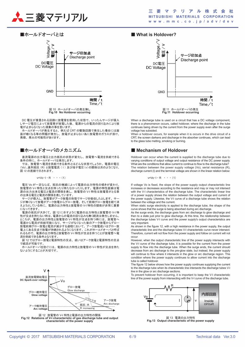
DC 電圧が重畳される回路に放電管を使用した状態で、 いったんサージが侵入しサージ電圧によって放電管が放電した後、 電源からの電流の回り込みにより放電が止まらなくなった現象の事を言います。 ホールドオーバが発生すると、 例えば CRT の駆動回路で発生した場合には画面が暗くなる等の問題が発生し、 放電が止まらない為に放電管のガラスが溶け、発煙、 発火の可能性があります。
When a discharge tube is used on a circuit that has a DC voltage component, there is a phenomenon occurs, called holdover, where the discharge in the tube continues being driven by the current from the power supply even after the surge voltage has subsided.When a holdover occurs, for example when it is occurs in the drive circuit of a CRT, the screen darkens and discharge in the absorber continues, which can lead to the glass tube melting, smoking or burning.
図 10 ホールドオーバの発生無しFig.10 No Holdover occurring
図 11 ホールドオーバの発生Fig.11 Holdover occurring
R
Vo内部回路Insidecircuit
Ⅰ v
直流電源の出力電圧と出力抵抗の状態が変化し、 放電管へ電流を供給できる条件の時に、 ホールドオーバは発生します。 では、 放電管へ電流を供給できる条件とはどんな状態でしょうか。 電源の電圧(Vo)、直列抵抗 (R) と放電電流 ( I ) 及び端子電圧(v)の関係は次のようになり、図 12 の直線で示されます。
v=Vo- I ・ R ・ ・ ・ (1)
電圧 Vo が一定ならば、 抵抗の増減によって電源の出力特性の傾きが変わり、放電管の V-I 特性と交点を持ったり持たなかったりします。 電源の特性直線は電源の出力出来る電圧と電流の関係を表し、 放電管の V-I 特性は放電管がとる事の出来る電圧と電流の関係を表しています。 サージが侵入し、 放電管がアーク放電の形態でサージを吸収したとします。 サージが無くなって放電がアーク放電からグロー放電、 そして前期グロー放電を経て消えようとしている時に、 電源の出力特性と放電管の V-I 特性の関係が非常に重要になってきます。 電源の抵抗が大きくて、 図 12 に示すように電源の出力特性と放電管の V-I 特性が交点を持たない時は、電源からの電流の回り込みも無く続流は発生しません。ところが、 電源の出力特性と放電管の V-I 特性が交点を持つ時には、 放電管へ電源から電流が供給可能になり、 サージがなくなった後のアーク放電からグロー放電前期グロー放電と電流が減少する過程において、 アーク放電或いはグロー放電上にある交点で放電が持続されるようになります。 これがホールドオーバと呼ばれるもので、 電源の出力特性と放電管の V-I 特性が交点を持つことが放電管へ電流を供給できる条件となります。 図 12 ではグロー放電と電源特性の交点、 或いはアーク放電と電源特性の交点で続流が可能です。 ホールドオーバを防ぐには、 電源の出力特性と放電管の V-I 特性が交点を持たないようにすることが大切です。
Holdover can occur when the current is supplied to the discharge tube due to varying conditions of output voltage and output resistance of the DC power supply. What are the conditions that allow current to continue to flow to the discharge tube? The relation between the power supply voltage (Vo), serial resistance (R), discharge current (I) and the terminal voltage are shown in the linear relation below:
v=Vo- I ・ R ・ ・ ・ (1)
If voltage Vo is fixed, the slope of the power supply output characteristic line increases or decreases according to the resistance and may or may not intersect with the V-I characteristics of the discharge tube. The characteristic linear line of a power supply shows the relation between the output voltage and current of the power supply. Likewise, the V-I curve of a discharge tube shows the relation between the voltage and the current. When static surge electricity is applied to the discharge tube, the shape of the curve shows that the surge is being absorbed during arc discharge. As the surge ends, the discharge goes from arc discharge to glow discharge and then to a state just prior to glow discharge. At this time, the relationship between the discharge tubes V-I curve and the power supply's output characteristics are very important. As shown in the figure 12, with a high resistance in the power supply, the output characteristic line and the discharge tubes V-I characteristic curve never intersect. Therefore, current will not flow from the power supply and follow on current will not occur. However, when the output characteristic line of the power supply intersects with the V-I curve of the discharge tube, it is possible for the current from the power supply to flow into the discharge tube. When the surge ends, the current should decrease from arc discharge to the pre-glow state, but instead, the power supply will continue to flow where it intersects in the glow or arc discharge region. This condition where the power supply continues to allow current into the discharge tube is called holdover. The figure 12 below shows how the power supply continues supplying the current to the discharge tube when its characteristic line intersects the discharge tubes V-I line in the glow or arc discharge sections. To prevent holdover from occurring, it is important to keep the V-I characteristic line of the power supply from intersecting with the V-I curve of the discharge tube.直流放電開始電圧
DC Spark-over voltage
グロー維持電圧Glow voltage
アーク維持電圧Arc voltage
グロー放電Glow discharge
アーク放電Arc discharge抵抗:大
R:increasing
V
Vo
v=Vo-I・R
図 12 放電管の V-I 特性と電源の出力特性の関係Fig.12 Relations of V-I characteristic of gas discharge tube and output
characteristic of the power supply図 13 電源の出力特性
Fig.13 Output characteristic of the power supply
■ホールドオーバとは
■ホールドオーバのメカニズム ■ Mechanism of Holdover
■ What is Holdover?
三 菱 マ テ リ ア ル 株 式 会 社MITSUBISHI MATERIALS CORPORATIONw w w . m m c . c o . j p / a d v / d e v
Copyright © 2017 MITSUBISHI MATERIALS CORPORATION Technical data Ver.3.07 / 9
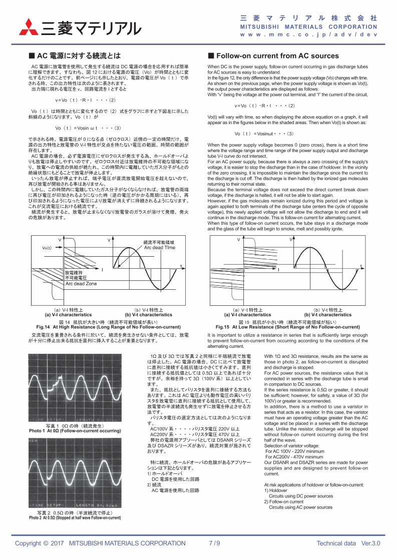
■ AC 電源に対する続流とは ■ Follow-on current from AC sources AC 電源に放電管を使用して発生する続流は DC 電源の場合を応用すれば簡単に理解できます。 すなわち、 図 12 における電源の電圧 (Vo) が時間とともに変化するだけのことです。 前ページにも示したとおり、 電源の電圧が Vo ( t ) で示される時、 この出力特性は次のように表されます。 出力端に現れる電圧を v、 回路電流を I とすると
v=Vo ( t ) -R ・ I ・ ・ ・ (2)
Vo ( t ) は時間とともに変化するので (2) 式をグラフに示すと下図左に示した斜線のようになります。 Vo ( t ) が
Vo ( t ) =Vosin ω t ・ ・ ・ (3)
で示される時、 電源電圧が 0 になる点 (ゼロクロス) 近傍の一定の時間だけ、 電源の出力特性と放電管の V-I 特性が交点を持たない電圧の範囲、 時間の範囲が存在します。 AC 電源の場合、 必ず電源電圧にゼロクロスが発生する為、 ホールドオーバよりも放電は停止しやすいのです。 ゼロクロス付近は放電維持の不可能な領域になり、 放電への電流の供給が絶たれ、 この時間内に電離していたガス分子がもとの絶縁状態にもどることで放電が停止します。 いったん放電が停止すれば、 端子電圧が直流放電開始電圧を超えないので、再び放電が開始される事はありません。 しかし、 この時間内に電離していたガス分子がなくならなければ、 放電管の両端に再び電圧が印加されるようになった時 (逆の電圧がかかる周期にはいる)、 再び印加されるようになった電圧により放電が消えずに持続されるようになります。これが交流電圧における続流です。 続流が発生すると、 放電が止まらなくなり放電管のガラスが溶けて発煙、 発火の危険があります。
1Ω 及び 3Ω では写真 2 と同様に半端続流で放電は停止した。 AC 電源の場合、 DC に比べて放電管に直列に接続する抵抗値は小さくてすみます。 直列に接続する抵抗値としては 0.5Ω 以上であれば十分ですが、 余裕を持って 3Ω (100V 系) 以上としています。 また、 抵抗としてバリスタを直列に接続する方法もあります。 これは AC 電圧よりも動作電圧の高いバリスタを放電管に直列に接続する抵抗として使用して、放電管の半波続流も発生せずに放電を停止させる方法です。 バリスタ電圧の選定方法としては次のようになります。 AC100V 系 ・ ・ ・ ・ バリスタ電圧 220V 以上 AC200V 系 ・ ・ ・ ・ バリスタ電圧 470V 以上 弊社の電源用アブソーバとしては DSANR シリーズ及び DSAZR シリーズがあり、 続流対策が施されております。
特に続流、 ホールドオーバの危険があるアプリケーションは下記となります。1) ホールドオーバ DC 電源を使用した回路2) 続流 AC 電源を使用した回路
When DC is the power supply, follow-on current occurring in gas discharge tubes for AC sources is easy to understand. In the figure 12, the only difference is that the power supply voltage (Vo) changes with time. As shown on the previous page, when the power supply voltage is shown as Vo(t), the output power characteristics are displayed as follows: With “v” being the voltage at the power out terminal, and “I” the current of the circuit,
v=Vo ( t ) -R ・ I ・ ・ ・ (2)
Vo(t) will vary with time, so when displaying the above equation on a graph, it will appear as in the figures below in the shaded areas. Then when Vo(t) is shown as:
Vo ( t ) =Vosinωt ・ ・ ・ (3)
When the power supply voltage becomes 0 (zero cross), there is a short time where the voltage range and time range of the power supply output and discharge tube V-I curve do not intersect. For an AC power supply, because there is always a zero crossing of the supply's voltage, it is easier to stop the discharge than in the case of holdover. In the vicinity of the zero crossing, it is impossible to maintain the discharge since the current to the discharge is cut off. The discharge is then halted by the ionized gas molecules returning to their normal state. Because the terminal voltage does not exceed the direct current break down voltage, if the discharge is halted, it will not be able to start again. However, if the gas molecules remain ionized during this period and voltage is again applied to both terminals of the discharge tube (enters the cycle of opposite voltage), this newly applied voltage will not allow the discharge to end and it will continue in the discharge mode. This is follow-on current for alternating current. When this type of follow-on current occurs, the tube stays in a discharge mode and the glass of the tube will begin to smoke, melt and possibly ignite.
With 1Ω and 3Ω resistance, results are the same as those in photo 2, as follow-on-current is disrupted and discharge is stopped.For AC power sources, the resistance value that is connected in series with the discharge tube is small in comparison to DC sources.If the series resistance is 0.5Ω or greater, it should be sufficient; however, for safety, a value of 3Ω (for 100V) or greater is recommended.In addition, there is a method to use a varistor in series that acts as a resistor. In this case, the varistor must have an operating voltage greater than the AC voltage and be placed in a series with the discharge tube. Unlike the resistor, discharge will be stopped without follow-on current occurring during the first half of the wave.Selection of varistor voltage: For AC 100V - 220V minimum For AC200V - 470V minimumOur DSANR and DSAZR series are made for power supplies and are designed to prevent follow-on current.
At risk applications of holdover or follow-on-current:1) Holdover Circuits using DC power sources2) Follow-on current Circuits using AC power sources
交流電圧を重畳される条件に於いて、 続流を発生させない条件としては、 放電が十分に停止出来る抵抗を直列に挿入することが重要となります。
It is important to utilize a resistance in series that is sufficiently large enough to prevent follow-on-current from occurring according to the conditions of the alternating current.
(a) V-I 特性上(a) V-I characteristics
(a) V-I 特性上(a) V-I characteristics
(b) V-t 特性上(b) V-t characteristics
(b) V-t 特性上(b) V-t characteristics
図 14 抵抗が大きい時 (続流不可能領域が長い)Fig.14 At High Resistance (Long Range of No Follow-on-current)
図 15 抵抗が小さい時 (続流不可能領域が短い)Fig.15 At Low Resistance (Short Range of No Follow-on-current)
写真 1 0Ω の時 (続流発生)Photo 1 At 0Ω (Follow-on-current occurring)
写真 2 0.5Ω の時 (半波続流で停止)Photo 2 At 0.5Ω (Stopped at half wave Follow-on-current)
三 菱 マ テ リ ア ル 株 式 会 社MITSUBISHI MATERIALS CORPORATIONw w w . m m c . c o . j p / a d v / d e v
Copyright © 2017 MITSUBISHI MATERIALS CORPORATION Technical data Ver.3.08 / 9
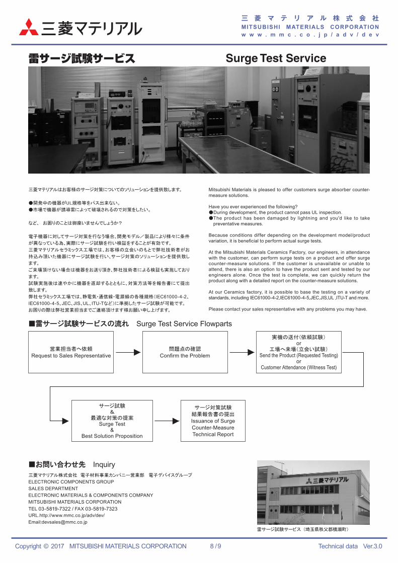
雷サージ試験サービス Surge Test Service
雷サージ試験サービス (埼玉県秩父郡横瀬町)
三菱マテリアルはお客様のサージ対策についてのソリューションを提供致します。
● 開発中の機器がUL規格等をパス出来ない。
● 市場で機器が誘導雷によって破壊されるので対策をしたい。
など、 お困りのことは御座いませんでしょうか?
電子機器に対してサージ対策を行なう場合、開発モデル/製品により様々に条件
が異なっている為、実際にサージ試験を行い検証をすることが有効です。
三菱マテリアルセラミックス工場では、お客様の立会いのもとで弊社技術者がお
持込み頂いた機器にサージ試験を行い、サージ対策のソリューションを提供致し
ます。
ご来場頂けない場合は機器をお送り頂き、弊社技術者による検証も実施しており
ます。
試験実施後は速やかに機器を返却するとともに、対策方法等を報告書にて提出
致します。
弊社セラミックス工場では、静電気・通信線・電源線の各種規格(IEC61000-4-2、
IEC61000-4-5、JEC、JIS、UL、ITU-Tなど)に準拠したサージ試験が可能です。
お困りの際は弊社営業担当までご連絡頂けます様お願い申し上げます。
Mitsubishi Materials is pleased to offer customers surge absorber counter-measure solutions.
Have you ever experienced the following?● During development, the product cannot pass UL inspection.● The product has been damaged by lightning and you'd like to take
preventative measures.
Because conditions differ depending on the development model/product variation, it is beneficial to perform actual surge tests.
At the Mitsubishi Materials Ceramics Factory, our engineers, in attendance with the customer, can perform surge tests on a product and offer surge counter-measure solutions. If the customer is unavailable or unable to attend, there is also an option to have the product sent and tested by our engineers alone. Once the test is complete, we can quickly return the product along with a detailed report on the counter-measure solutions.
At our Ceramics factory, it is possible to base the testing on a variety of standards, including IEC61000-4-2,IEC61000-4-5,JEC,JIS,UL ,ITU-T and more.
Please contact your sales representative with any problems you may have.
■雷サージ試験サービスの流れ Surge Test Service Flowparts
営業担当者へ依頼
Request to Sales Representative問題点の確認
Confirm the Problem
実機の送付(依頼試験)or
工場へ来場(立会い試験)Send the Product (Requested Testing)
orCustomer Attendance (Witness Test)
サージ試験&
最適な対策の提案Surge Test
&Best Solution Proposition
サージ対策試験
結果報告書の提出
Issuance of Surge Counter-MeasureTechnical Report
■お問い合わせ先 Inquiry三菱マテリアル株式会社 電子材料事業カンパニー営業部 電子デバイスグループ
ELECTRONIC COMPONENTS GROUPSALES DEPARTMENTELECTRONIC MATERIALS & COMPONENTS COMPANYMITSUBISHI MATERIALS CORPORATIONTEL 03-5819-7322 / FAX 03-5819-7323URL.http://www.mmc.co.jp/adv/dev/Email:[email protected]
三 菱 マ テ リ ア ル 株 式 会 社MITSUBISHI MATERIALS CORPORATIONw w w . m m c . c o . j p / a d v / d e v
Copyright © 2017 MITSUBISHI MATERIALS CORPORATION Technical data Ver.3.09 / 9
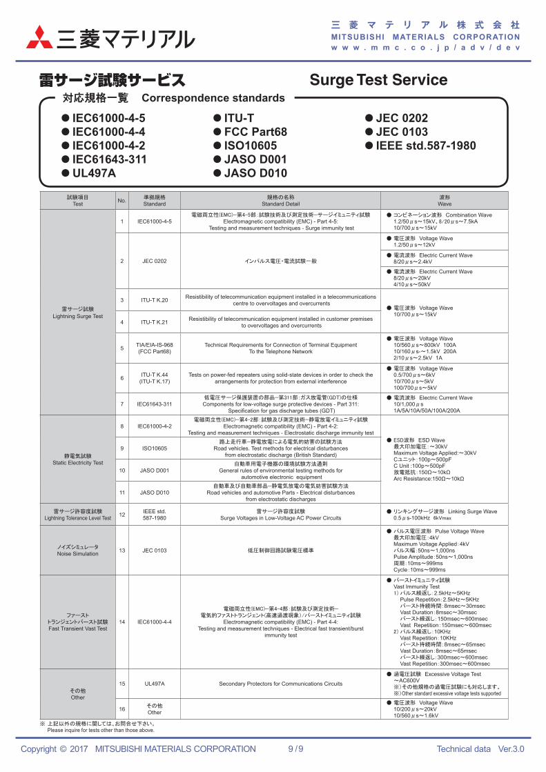
雷サージ試験サービス Surge Test Service対応規格一覧 Correspondence standards
● IEC61000-4-5● IEC61000-4-4● IEC61000-4-2● IEC61643-311● UL497A
● ITU-T● FCC Part68● ISO10605● JASO D001● JASO D010
● JEC 0202● JEC 0103● IEEE std.587-1980
試験項目Test No. 準拠規格
Standard規格の名称
Standard Detail波形Wave
雷サージ試験
Lightning Surge Test
1 IEC61000-4-5電磁両立性(EMC)−第4-5部:試験技術及び測定技術−サージイミュニティ試験
Electromagnetic compatibility (EMC) - Part 4-5: Testing and measurement techniques - Surge immunity test
● コンビネーション波形 Combination Wave 1.2/50μs〜15kV、8/20μs〜7.5kA 10/700μs〜15kV
2 JEC 0202 インパルス電圧・電流試験一般
● 電圧波形 Voltage Wave 1.2/50μs〜12kV
● 電流波形 Electric Current Wave 8/20μs〜2.4kV
● 電流波形 Electric Current Wave 8/20μs〜20kV 4/10μs〜50kV
3 ITU-T K.20 Resistibility of telecommunication equipment installed in a telecommunications centre to overvoltages and overcurrents
● 電圧波形 Voltage Wave 10/700μs〜15kV
4 ITU-T K.21 Resistibility of telecommunication equipment installed in customer premises to overvoltages and overcurrents
5 TIA/EIA-IS-968(FCC Part68)
Technical Requirements for Connection of Terminal EquipmentTo the Telephone Network
● 電圧波形 Voltage Wave 10/560μs〜800kV 100A 10/160μs-〜1.5kV 200A 2/10μs〜2.5kV 1A
6 ITU-T K.44(ITU-T K.17)
Tests on power-fed repeaters using solid-state devices in order to check the arrangements for protection from external interference
● 電圧波形 Voltage Wave 0.5/700μs〜6kV 10/700μs〜5kV 100/700μs〜5kV
7 IEC61643-311低電圧サージ保護装置の部品−第311部:ガス放電管(GDT)の仕様Components for low-voltage surge protective devices - Part 311:
Specification for gas discharge tubes (GDT)
● 電流波形 Electric Current Wave 10/1,000μs 1A/5A/10A/50A/100A/200A
静電気試験Static Electricity Test
8 IEC61000-4-2電磁両立性(EMC)−第4-2部:試験及び測定技術−静電放電イミュニティ試験
Electromagnetic compatibility (EMC) - Part 4-2: Testing and measurement techniques - Electrostatic discharge immunity test
● ESD波形 ESD Wave 最大印加電圧:〜30kV Maximum Voltage Applied:〜30kV Cユニット:100p〜500pF C Unit :100p〜500pF 放電抵抗:150Ω〜10kΩ Arc Resistance:150Ω〜10kΩ
9 ISO10605路上走行車−静電放電による電気的妨害の試験方法
Road vehicles. Test methods for electrical disturbances from electrostatic discharge (British Standard)
10 JASO D001自動車用電子機器の環境試験方法通則
General rules of environmental testing methods for automotive electronic equipment
11 JASO D010自動車及び自動車部品−静電気放電の電気妨害試験方法
Road vehicles and automotive Parts - Electrical disturbances from electrostatic discharges
雷サージ許容度試験Lightning Tolerance Level Test 12 IEEE std.
587-1980雷サージ許容度試験
Surge Voltages in Low-Voltage AC Power Circuits● リンキングサージ波形 Linking Surge Wave 0.5μs-100kHz 6kVmax
ノイズシミュレータNoise Simulation 13 JEC 0103 低圧制御回路試験電圧標準
● パルス電圧波形 Pulse Voltage Wave 最大印加電圧:4kV Maximum Voltage Applied:4kV パルス幅:50ns〜1,000ns Pulse Amplitude:50ns〜1,000ns 周期:10ms〜999ms Cycle:10ms〜999ms
ファーストトランジェントバースト試験Fast Transient Vast Test
14 IEC61000-4-4
電磁両立性(EMC)−第4-4部:試験及び測定技術−電気的ファストトランジェント(高速過渡現象)/バーストイミュニティ試験
Electromagnetic compatibility (EMC) - Part 4-4: Testing and measurement techniques - Electrical fast transient/burst
immunity test
● バーストイミュニティ試験 Vast Immunity Test 1) パルス繰返し:2.5kHz〜5KHz Pulse Repetition:2.5kHz〜5KHz バースト持続時間:8msec〜30msec Vast Duration:8msec〜30msec バースト繰返し:150msec〜600msec Vast Repetition:150msec〜600msec 2) パルス繰返し:10KHz Vast Repetition:10KHz バースト持続時間:8msec〜65msec Vast Duration:8msec〜65msec バースト繰返し:300msec〜600msec Vast Repetition:300msec〜600msec
その他Other
15 UL497A Secondary Protectors for Communications Circuits
● 過電圧試験 Excessive Voltage Test 〜AC600V ※)その他規格の過電圧試験にも対応します。 ※)Other standard excessive voltage tests supported
16 その他Other
● 電圧波形 Voltage Wave 10/200μs〜20kV 10/560μs〜1.6kV
※ 上記以外の規格に関しては、お問合せ下さい。 Please inquire for tests other than those above.


![(MLV) MULTILAYER CHIP VARISTOR - fenghua.comfenghua.com/pdf/varistor/chip_varistor.pdf · (MLV) MULTILAYER CHIP VARISTOR Multilayer Chip ... [2220] 8063[3225] 1080[4032] 55 125 V](https://img.pdfslide.net/doc/110x75/5b42af3a7f8b9ad23b8b5240/mlv-multilayer-chip-varistor-mlv-multilayer-chip-varistor-multilayer-chip.jpg)