Embed Size (px)
Citation preview
EET 252
Digital Systems II
Professor Nick Reeder
Reminders
Please turn off cell phones.
No food or soft drinks in the classroom.
Stow water bottles at floor level.
EET 252 Unit 1Review; Arithmetic Logic Units
Review Floyd, Chapter 2 and Chapters 6 to 9.
Study Unit 1 e-Lesson. Do Lab #1.
Homework #1 and Lab #1 due next week.
Quiz next week.
Overview of This Week’s Lecture
Unused Inputs Pull-up Resistors Review of Logical Operations Review of Arithmetic Operations Arithmetic Logic Units
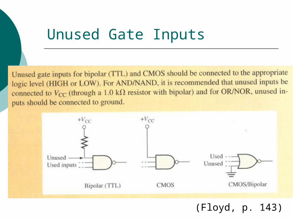
Unused Gate Inputs
(Floyd, p. 143)
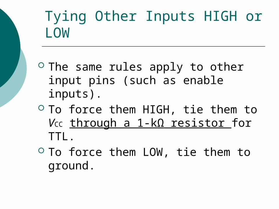
Tying Other Inputs HIGH or LOW
The same rules apply to other input pins (such as enable inputs).
To force them HIGH, tie them to VCC through a 1-kΩ resistor for TTL.
To force them LOW, tie them to ground.
But what about the Trainer’s Data Switches?
When you connect a TTL input pin to one of the trainer’s data switches and set the switch to HIGH, do you need a 1−kΩ resistor between the switch and the input pin?
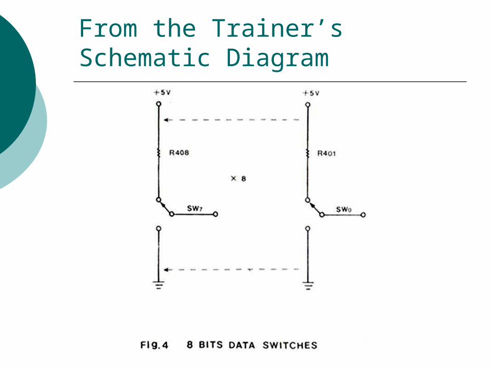
From the Trainer’s Schematic Diagram
Don’t Tie Outputs HIGH or LOW
Remember that, in general, unused output pins should be left unconnected. Do not tie them HIGH or LOW.
Overview of This Week’s Lecture
Unused Inputs Pull-up Resistors Review of Logical Operations Review of Arithmetic Operations Arithmetic Logic Units
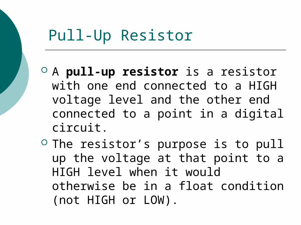
Pull-Up Resistor
A pull-up resistor is a resistor with one end connected to a HIGH voltage level and the other end connected to a point in a digital circuit.
The resistor’s purpose is to pull up the voltage at that point to a HIGH level when it would otherwise be in a float condition (not HIGH or LOW).
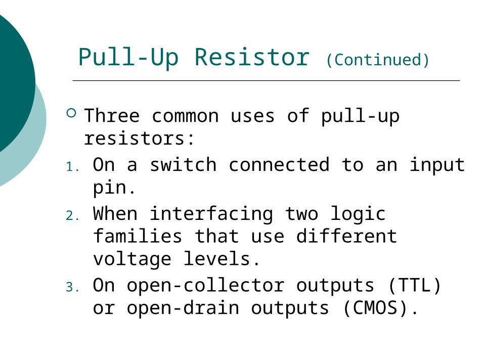
Pull-Up Resistor (Continued)
Three common uses of pull-up resistors: 1. On a switch connected to an input pin. 2. When interfacing two logic families
that use different voltage levels.3. On open-collector outputs (TTL) or
open-drain outputs (CMOS).
First Use for Pull-Up Resistor: Switch on an Input Pin
Good explanation at http://www.seattlerobotics.org/encoder/mar97/basics.html
See also example on next slide from your textbook.
Copyright ©2009 by Pearson Higher Education, Inc.Upper Saddle River, New Jersey 07458
All rights reserved.
Digital Fundamentals, Tenth EditionThomas L. Floyd
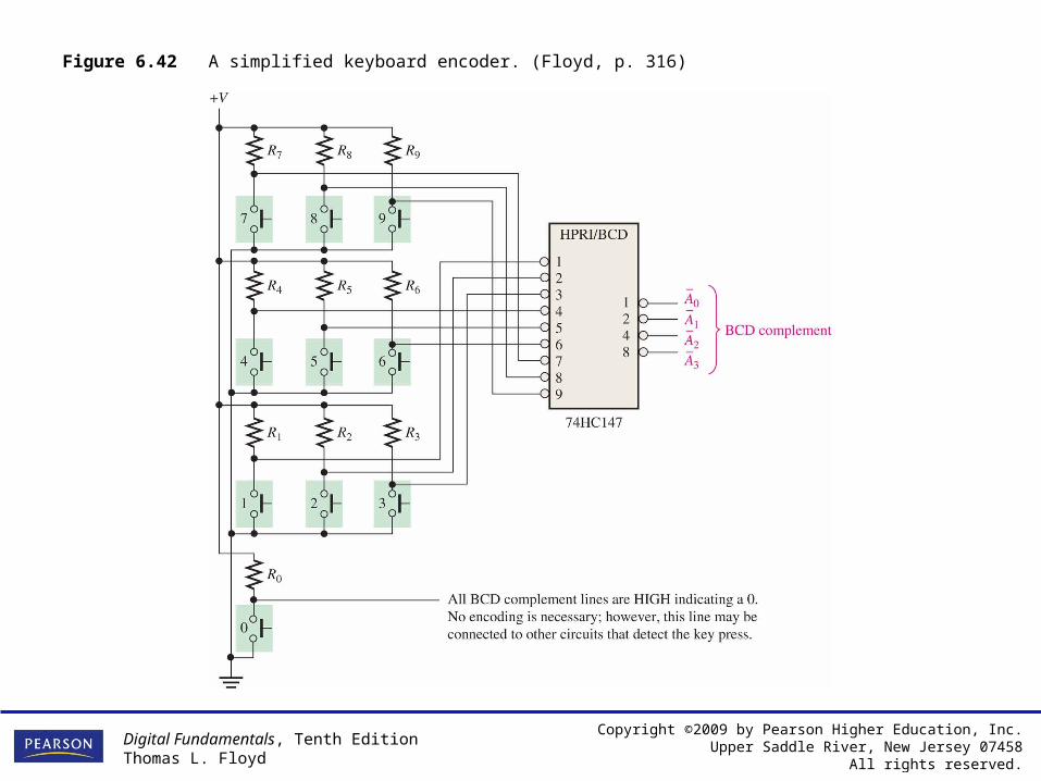
Figure 6.42 A simplified keyboard encoder. (Floyd, p. 316)
Second Use for Pull-Up Resistor: Interfacing Logic Families
Suppose we want to connect the output of a TTL gate to the input of a CMOS gate.
A TTL HIGH output may be as low as 2.4 V.
But CMOS expects at least 3.3 V for a HIGH.
Problem: The CMOS gate may interpret the TTL gate’s HIGH output as a LOW.
Solution? See next slide.
Digital Electronics: A Practical Approach, Eighth EditionWilliam Kleitz
Copyright ©2008 by Pearson Education, Inc.Upper Saddle River, New Jersey 07458
All rights reserved.
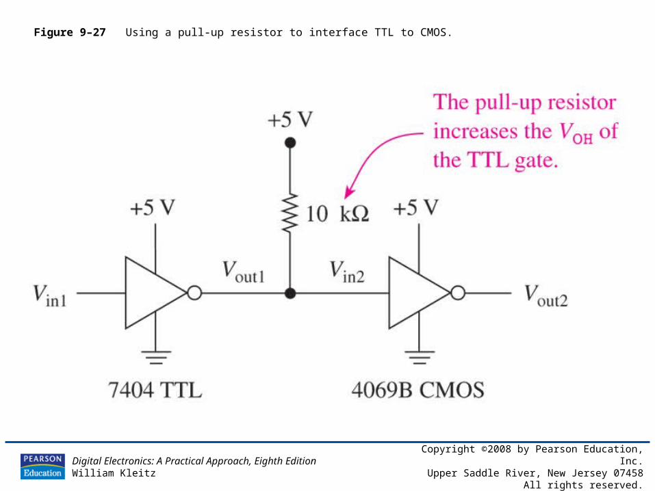
Figure 9–27 Using a pull-up resistor to interface TTL to CMOS.
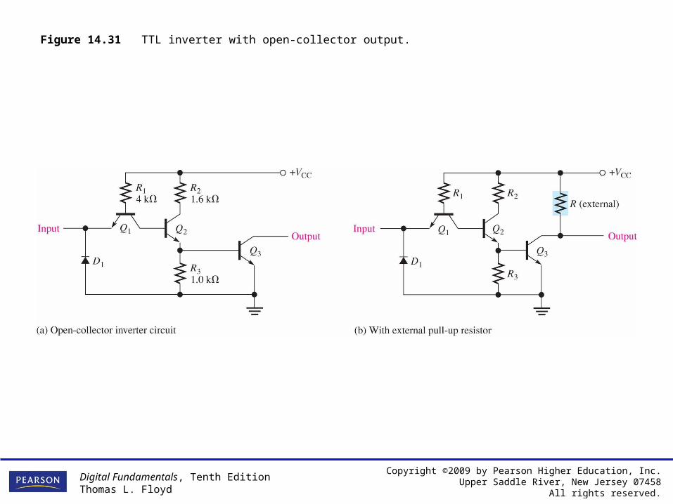
Third Use for Pull-Up Resistor: Open Collector Outputs
As we’ll see next week, some TTL gates are intentionally designed with a missing transistor on the output. To work properly, such an output needs an external pull-up resistor.
One of the output pins on the chip in tonight’s lab is an open-collector output, and therefore needs a pull-up resistor.
Copyright ©2009 by Pearson Higher Education, Inc.Upper Saddle River, New Jersey 07458
All rights reserved.
Digital Fundamentals, Tenth EditionThomas L. Floyd
Figure 14.31 TTL inverter with open-collector output.
Overview of This Week’s Lecture
Unused Inputs Pull-up Resistors Review of Logical Operations Review of Arithmetic Operations Arithmetic Logic Units
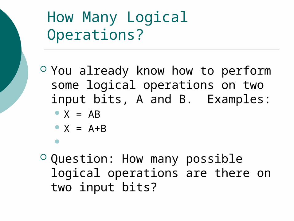
How Many Logical Operations?
You already know how to perform some logical operations on two input bits, A and B. Examples: X = AB X = A+B
Question: How many possible logical operations are there on two input bits?
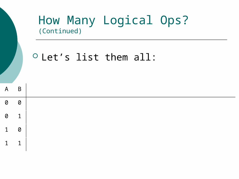
How Many Logical Ops? (Continued)
Let’s list them all:
A B
0 0
0 1
1 0
1 1
Overview of This Week’s Lecture
Unused Inputs Pull-up Resistors Review of Logical Operations Review of Arithmetic Operations Arithmetic Logic Units
Overview of This Week’s Lecture
Unused Inputs Pull-up Resistors Review of Logical Operations Review of Arithmetic Operations Arithmetic Logic Units
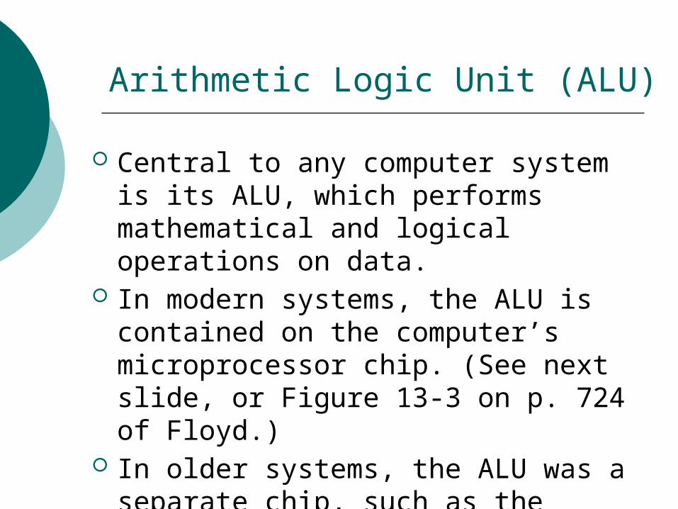
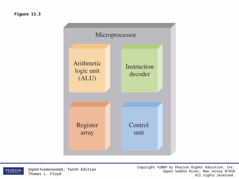
Arithmetic Logic Unit (ALU)
Central to any computer system is its ALU, which performs mathematical and logical operations on data.
In modern systems, the ALU is contained on the computer’s microprocessor chip. (See next slide, or Figure 13-3 on p. 724 of Floyd.)
In older systems, the ALU was a separate chip, such as the 74181.
Copyright ©2009 by Pearson Higher Education, Inc.Upper Saddle River, New Jersey 07458
All rights reserved.
Digital Fundamentals, Tenth EditionThomas L. Floyd
Figure 13.3
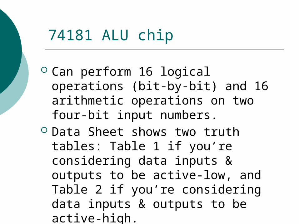
74181 ALU chip
Can perform 16 logical operations (bit-by-bit) and 16 arithmetic operations on two four-bit input numbers.
Data Sheet shows two truth tables: Table 1 if you’re considering data inputs & outputs to be active-low, and Table 2 if you’re considering data inputs & outputs to be active-high.
Data Sheet: 74LS181
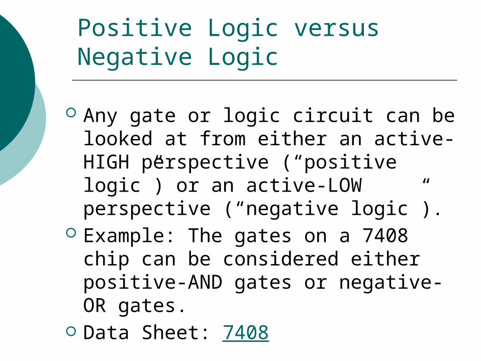
Positive Logic versus Negative Logic
Any gate or logic circuit can be looked at from either an active-HIGH perspective (“positive logic”) or an active-LOW perspective (“negative logic”).
Example: The gates on a 7408 chip can be considered either positive-AND gates or negative-OR gates.
Data Sheet: 7408
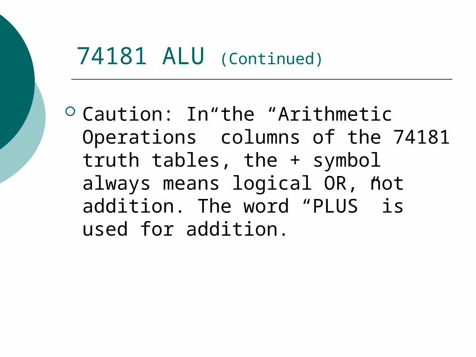
74181 ALU (Continued)
Caution: In the “Arithmetic Operations” columns of the 74181 truth tables, the + symbol always means logical OR, not addition. The word “PLUS” is used for addition.
74181 ALU (Continued)
Fourteen Input Pins: M is the mode pin (arithmetic or logic). S0 to S3 select the operation performed. Cn is the carry-in bit, used only during
arithmetic ops (ignored during logic ops). A0 to A3 form one of the 4-bit inputs. B0 to B3 form the other 4-bit input.
74181 ALU (Continued)
Eight Output Pins: F0 to F3 form the 4-bit output. Cn=4 is carry-out bit, meaningful only for
arithmetic ops. (Ignore it for logic ops.) A=B is comparison bit, meaningful only
when performing “A MINUS B” operation. (Ignore it for all other ops.)
P and G are carry-look-ahead bits for high-speed arithmetic, when 74181 is used in conjunction with 74182 chip. (We’ll ignore these.)