Embed Size (px)
Citation preview
Generator
LIT-19626-01-20 7CH-28199-10PRINTED ON RECYCLED PAPERPRINTED IN JAPAN04 906 – 0.4 × 1 !
EF3000iSEEF3000iSEB
OWNER’S MANUAL
7CH-9-10 hyoshi 4/22/04 10:20 AM Page 1

7CH-9-10 hyoshi 4/22/04 10:20 AM Page 2

AE00012
IDENTIFICATION NUMBER RECORDSRecord your Primary I.D., and serial num-bers in the spaces provided, to assist youin ordering spare parts from a Yamahadealer.Also record and keep these I.D. numbers ina separate place in case your machine isstolen.
AE00002
INTRODUCTIONCongratulations on your purchase of your new Yamaha.This manual will provide you with a good basic understanding of the operation and main-tenance of this machine.If you have any questions regarding the operation or maintenance of your machine,please consult a Yamaha dealer.
PRI-I.D. NUMBER
PRI-I.D.CODE SERIAL No.
EF3000iSEEF3000iSEB
OWNER’S MANUAL© 2004 by Yamaha Motor Corporation, U.S.A.
1st Edition, April 2004All rights reserved.
Any reprinting or unauthorized usewithout the written permission of Yamaha Motor Corporation, U.S.A.
is expressly prohibited.Printed in Japan.
P/N LIT-19626-01-20
MODEL
790-066c
7CH-24163-**
AE00022
AE00011
MACHINE IDENTIFICATIONThe machine serial number is stamped inthe location as shown.
NOTE:The first three digits of these numbers arefor model identification; the remaining dig-its are the unit production number. Keep arecord of these numbers for referencewhen ordering parts from a Yamaha dealer.
7CH-9-10-a 5/18/04 2:22 PM Page 0-1

NOTE:9 Yamaha continually seeks advance-
ments in product design and quality.Therefore, while this manual containsthe most current product informationavailable at the time of printing, theremay be minor discrepancies betweenyour engine and this manual. If there isany question concerning this manual,please consult your Yamaha dealer.
9 This manual should be considered apermanent part of this engine andshould remain with this engine whenresold.
AE00032
wPLEASE READ AND UNDERSTANDTHIS MANUAL COMPLETELY BEFOREOPERATING THE MACHINE.
Particularly important information is distin-guished in this manual by the followingnotations.
-The Safety Alert Symbol means ATTEN-TION! BECOME ALERT! YOUR SAFETYIS INVOLVED!
wFailure to follow WARNING instructionscould result in severe injury or death to theengine operator, a bystander, or a personinspecting or repairing the engine.
cCA CAUTION indicates special precautionsthat must be taken to avoid damage to theengine.
NOTE:A NOTE provides key information to makeprocedures easier or clearer.
7CH-9-10-a 5/18/04 2:22 PM Page 0-2
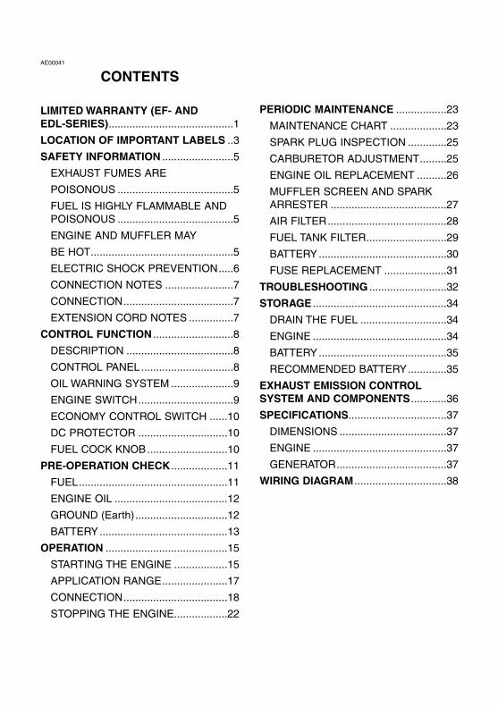
AE00041
CONTENTS
LIMITED WARRANTY (EF- AND EDL-SERIES)..........................................1
LOCATION OF IMPORTANT LABELS ..3
SAFETY INFORMATION ........................5
EXHAUST FUMES ARE
POISONOUS .......................................5
FUEL IS HIGHLY FLAMMABLE ANDPOISONOUS .......................................5
ENGINE AND MUFFLER MAY
BE HOT................................................5
ELECTRIC SHOCK PREVENTION.....6
CONNECTION NOTES .......................7
CONNECTION.....................................7
EXTENSION CORD NOTES ...............7
CONTROL FUNCTION ...........................8
DESCRIPTION ....................................8
CONTROL PANEL ...............................8
OIL WARNING SYSTEM .....................9
ENGINE SWITCH................................9
ECONOMY CONTROL SWITCH ......10
DC PROTECTOR ..............................10
FUEL COCK KNOB...........................10
PRE-OPERATION CHECK ...................11
FUEL..................................................11
ENGINE OIL ......................................12
GROUND (Earth)...............................12
BATTERY...........................................13
OPERATION .........................................15
STARTING THE ENGINE ..................15
APPLICATION RANGE......................17
CONNECTION...................................18
STOPPING THE ENGINE..................22
PERIODIC MAINTENANCE .................23
MAINTENANCE CHART ...................23
SPARK PLUG INSPECTION .............25
CARBURETOR ADJUSTMENT.........25
ENGINE OIL REPLACEMENT ..........26
MUFFLER SCREEN AND SPARKARRESTER .......................................27
AIR FILTER........................................28
FUEL TANK FILTER...........................29
BATTERY...........................................30
FUSE REPLACEMENT .....................31
TROUBLESHOOTING ..........................32
STORAGE .............................................34
DRAIN THE FUEL .............................34
ENGINE .............................................34
BATTERY...........................................35
RECOMMENDED BATTERY.............35
EXHAUST EMISSION CONTROL SYSTEM AND COMPONENTS............36
SPECIFICATIONS.................................37
DIMENSIONS ....................................37
ENGINE .............................................37
GENERATOR.....................................37
WIRING DIAGRAM ...............................38
7CH-9-10-a 5/18/04 2:22 PM Page 0-3
– 1 –
AE01120
YAMAHA MOTOR CORPORATION U.S.A.EF- AND EDL-SERIES GENERATOR LIMITED WARRANTY
Yamaha Motor Corporation, U.S.A. hereby warrantsthat new Yamaha consumer generators purchasedfrom an authorized Yamaha consumer generatordealer in the continental United States will be freefrom defects in material and workmanship for theperiod of time stated herein, subject to certain stat-ed limitations.
THE PERIOD OF WARRANTY Any new EF-seriesor EDL-series Yamaha Generator purchased forprivate, non-commercial use from an authorizedYamaha consumer generator dealer in the conti-nental United States will be warranted against defects in material or work-manship for a period two (2) years from date of pur-chase, subject to exclusions noted herein. AnyYamaha non-commercial generator purchased and utilized for commercial orrental applications will be warranted for a periodone (1) year from the date of purchase, subject toexclusions noted herein.
DURING THE PERIOD OF WARRANTY anyauthorized Yamaha consumer generator dealer will,free of charge, repair or replace, at Yamaha’soption, any part adjudged defective by Yamaha dueto faulty workmanship or material from the factory.Parts used in warranty repairs will be warranted forthe balance of the product’s warranty period. Allparts replaced under warranty become property ofYamaha Motor Corporation U.S.A.
GENERAL EXCLUSIONS from this warranty shallinclude any failures caused by:a. Installation of parts or accessories that are not
qualitatively equivalent to genuine Yamahaparts.
b. Abnormal strain, neglect, or abuse.c. Lack of proper maintenance.d. Accident or collision damage.
SPECIFIC EXCLUSIONS from this warranty shallinclude parts replaced due to normal wear or rou-tine maintenance.
THE CUSTOMER’S RESPONSIBILITY under thiswarranty shall be to:1. Operate and maintain the generator as speci-
fied in the appropriate Owner’s Manual;
2. Give notice to an authorized Yamaha con-sumer generator dealer of any and all apparentdefects within ten (10) days after discovery,and make the unit available at that time forinspection and repairs at such dealer’s place ofbusiness.
WARRANTY TRANSFER: To transfer the warrantyfrom the original purchaser to any subsequent pur-chaser(s), it is imperative that the unit be inspectedand registered for warranty by an authorizedYamaha consumer generator dealer. In order forthis warranty to remain in effect, this inspection andregistration must take place within ten (10) daysafter transfer. An inspection and registration fee willbe charged for this service. In no case will the war-ranty be extended beyond the original period.
YAMAHA MOTOR CORPORATION, U.S.A. MAKESNO OTHER WARRANTY OF ANY KIND,EXPRESSED OR IMPLIED. ALL IMPLIED WAR-RANTIES OF MERCHANTABILITY AND FITNESSFOR A PARTICULAR PURPOSE WHICH EXCEEDTHE OBLIGATIONS AND TIME LIMITS STATED INTHIS WARRANTY ARE HEREBY DISCLAIMED BYYAMAHA MOTOR CORPORATION, U.S.A. ANDEXCLUDED FROM THIS WARRANTY.
SOME STATES DO NOT ALLOW LIMITATIONS ONHOW LONG AN IMPLIED WARRANTY LASTS, SOTHE ABOVE LIMITATION MAY NOT APPLY TO YOU.ALSO EXCLUDED FROM THIS WARRANTY AREANY INCIDENTAL OR CONSEQUENTIAL DAM-AGES INCLUDING LOSS OF USE. SOME STATESDO NOT ALLOW THE EXCLUSION OR LIMITATIONOF INCIDENTAL OR CONSEQUENTIAL DAMAGES,SO THE ABOVE EXCLUSION MAY NOT APPLY TOYOU.
THIS WARRANTY GIVES YOU SPECIFIC LEGALRIGHTS, AND YOU MAY ALSO HAVE OTHERRIGHTS WHICH VARY FROM STATE TO STATE.
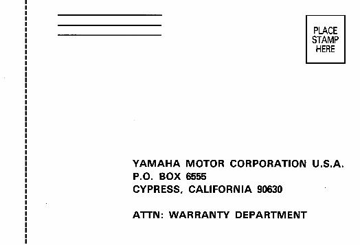
YAMAHA MOTOR CORPORATION, U.S.A.Post Office Box 6555
Cypress, California 90630
7CH-9-10-a 5/18/04 2:22 PM Page 1
– 2 –
WARRANTY QUESTIONS AND ANSWERS
Q. What costs are my responsibility during thewarranty period?
A. The customer’s responsibility includes all costsof normal maintenance service, non-warrantyrepairs, accident damages, as well as oil andspark plugs.
Q. What are some examples of “abnormal” strain,neglect, or abuse?
A. These terms are general and overlap eachother in areas. Specific examples include:Running the machine out of oil; lack of propermaintenance; operating the machine with abroken or damaged part which causes anoth-er part to fail; and so on. If you have any spe-cific questions on operation or maintenance,please contact your dealer for advice.
Q. Does the warranty cover incidental costs suchas transportation due to a failure?
A. No. The warranty is limited to repair of themachine itself.
Q. May I perform any or all of the recommendedmaintenance shown in the Owner’s Manualinstead of having the dealer do them?
A. Yes, if you are a qualified mechanic and followthe procedures specified in the Owner’s andService Manual. We do recommend, however,that items requiring special tools or equipmentbe done by a Yamaha generator dealer.
Q. Will the warranty be void or cancelled if I do notoperate or maintain my new Yamaha exactly asspecified in the Owner’s Manual?
A. No. The warranty on a new Yamaha cannot be“voided” or “cancelled.”However, if a particular failure is caused byoperation or maintenance other than asshown in the Owner’s Manual, that failuremay not be covered under warranty.
Q. What responsibility does my dealer have underthis warranty?
A. Each Yamaha generator dealer is expected to:1. Check the operation of the generator
before sale.2. Explain the operation, maintenance, and
warranty requirements to your satisfactionat the time of sale, and upon your requestat any later date.
In addition, each Yamaha generator dealer isheld responsible for his setup, service and war-ranty repair work.
Q. Is the warranty transferable to second owners?A. Yes. The remainder of the existing warranty
can be transfered upon request.The unit has to be inspected and reregisteredby an authorized Yamaha generator dealer forthe policy to remain effective.
CUSTOMER SERVICE
If your machine requires warranty service, youmust take it to any authorized Yamaha generatordealer within the continental United States. Be sureto bring your warranty registration identification orother valid proof of the original date of purchase. Ifa question or problem arises regarding warranty,first contact the owner of the dealership. Since allwarranty matters are handled at the dealer level,this person is in the best position to help you. If youare still not satisfied and require additional assis-tance, please write:
YAMAHA MOTOR CORPORATION U.S.A.CUSTOMER RELATIONS DEPARTMENT
P.O. BOX 6555Cypress, California 90630
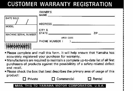
CHANGE OF ADDRESS
The federal government requires each manufactur-er to maintain a complete, up-to-date list of all firstpurchasers against the possibility of a safety-relat-ed defect and recall. This list is compiled from thepurchase registrations sent to Yamaha MotorCorporation, U.S.A. by the selling dealer at the timeof your purchase. If you should move after you havepurchased your new generator, please advise us ofyour new address by sending a postcard listingyour Yamaha model name, engine number, dealernumber (or dealer’s name) as it is shown on yourwarranty identification, your name and new mailingaddress. Mail to:
YAMAHA MOTOR CORPORATION, U.S.A.WARRANTY DEPARTMENT
P.O. Box 6555Cypress, California 90630
This will ensure that Yamaha Motor Corporation,U.S.A. has an up-to-date registration record inaccordance with federal law.
7CH-9-10-a 5/18/04 2:22 PM Page 2

– 3 –
AE00062
LOCATION OF IMPORTANT LABELSPlease read the following labels carefully before oper-ating this machine.
NOTE:Maintain or replace safety and instruction labels, asnecessary.
e
q
792-052c
w
r
792-053c
7CH-9-10-a 5/18/04 2:22 PM Page 3

– 4 –
1 2
4
3
WARNINGREAD THE OWNER‘S MANUAL AND ALL LABELS BEFORE OPERATING.
q qAVERTISSEMENT8
ONLY OPERATE IN WELL-VENTILATED AREA.EXHAUST GAS CONTAINS POISONOUS CARBON MONOXIDE.CHECK FOR SPILLED FUEL OR FUEL LEAKS.STOP ENGINE BEFORE REFUELING.DO NOT OPERATE NEAR FLAMMABLE MATERIALS.ELECTROCUTION CAN OCCUR IF GENERATOR IS USED IN RAIN,SNOW, OR NEAR WATER. KEEP THIS UNIT DRY AT ALL TIMES.
8
8888
MACHINE AU SEC EN TOUTES CIRCONSTANCES.7NJ-24162-10
8
8
8888
LISEZ LE MODE D‘EMPLOI ET TOUTES LES ETIQUETTES AVANT DEFAIRE FONCTIONNER LA MACHINE.FAITES FONCTIONNER UNIQUEMENT DANS DES LIEUX BIEN AERES.LES GAZ D‘ECHAPPEMENT CONTIENNENT DU MONOXYDE DE CARBONE.VERIFIEZ SI DU CARBURANT A ETE RENVERSE DU S‘IL FUIT.ARRETEZ LE MOTEUR AVANT DE FAIRE LE PLEIN DE CARBURANT.N‘UTILISEZ PAS A PROXIMITE DE MATERIAUX INFLAMMABLES.IL Y A RISQUE D‘ELECTROCUTION SI LE GENERATEUR FONCTIONNESOUS LA PLUIE, DANS LA NEIGE, OU PRES DE L‘EAU. GARDEZ LAMACHINE AU SEC EN TOUTES CIRCONSTANCES.
0 2 4 6 8 1 0
ENGINE AIR INDEX ( C a l i f o r n i a o n l y )
LEAST CLEANMOST C L E A NN O T E : T H E L O W E R T H E A I R I N D E X , T H E L E S S T H E P O L L U T I O N
F O R T H E F O L L O W I N G U S E :
T H I S E N G I N E I S C E R T I F I E D T O B E E M I S S I O N C O M P L I A N T
MODERATE INTERMEDIATE EXTENDEDCHECK OWNERS M A N U A L F O R F U R T H E R D E T A I L S
T H I S L A B E L T O B E R E M O V E D B Y T H E U L T I M A T E P U R C H A S E R O N L Y !
IMPORTANT ENGINE INFORMATIONENGINE FAMILY : zzzzzzzzzzzzE M
REFER TO OWNER'S MANUAL FOR MAINTENANCE SPECIFICATIONS AND ADJUSTMENTS.
YAMAHA MOTOR CO. LTD
DISPLACEMENT: VALVE LASH (A)
rpm
NO OTHER ADJUSTMENTS NEEDED.
ENGINE OIL:
IDLE SPEED:
FUEL: THIS ENGINE IS CERTIFIED TO OPERATE ON UNLEADED GASOLINE.
IGNITION TIMING & IDLE MIXTUREzzzJ IN:
TYPE
z.zz~z.zz EX:z.zz~z.zz
zzzz~zzzz AT NO LOAD
SESAE 10W-30THIS ENGINE MEETS zzzz-zzzz CALIFORNIA EMISSION REGULATIONS FOR SMALL OFF-ROAD ENGINES.THIS ENGINE CONFORMS TO PHASE 2 U.S.EPA REGULATIONS FOR SMALL NONROAD ENGINES.EMISSIONS COMPLIANCE PERIOD:CATEGORY A (EPA) zzz-2179R-00
HOT EXHAUST***-28176-**
OIL
zzzzzz
AC output zzHz
Rated zzzKVA
Phase Single
DC output zzV zzA
Fuel Gasoline
YAMAHA MOTOR CO., LTD.MADE IN JAPAN
zzzV
***-24164-**
7CH-9-10-a 5/18/04 2:22 PM Page 4
– 5 –
741-092
741-093
741-094
741-095a
741-096
741-097
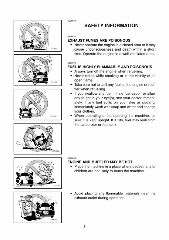
AE00071
SAFETY INFORMATION
AE00072
EXHAUST FUMES ARE POISONOUS9 Never operate the engine in a closed area or it may
cause unconsciousness and death within a shorttime. Operate the engine in a well ventilated area.
AE00075
FUEL IS HIGHLY FLAMMABLE AND POISONOUS9 Always turn off the engine when refuelling.9 Never refuel while smoking or in the vicinity of an
open flame.9 Take care not to spill any fuel on the engine or muf-
fler when refuelling.9 If you swallow any fuel, inhale fuel vapor, or allow
any to get in your eye(s), see your doctor immedi-ately. If any fuel spills on your skin or clothing,immediately wash with soap and water and changeyour clothes.
9 When operating or transporting the machine, besure it is kept upright. If it tilts, fuel may leak fromthe carburetor or fuel tank.
AE00843
ENGINE AND MUFFLER MAY BE HOT9 Place the machine in a place where pedestrians or
children are not likely to touch the machine.
9 Avoid placing any flammable materials near theexhaust outlet during operation.
7CH-9-10-a 5/18/04 2:22 PM Page 5
– 6 –
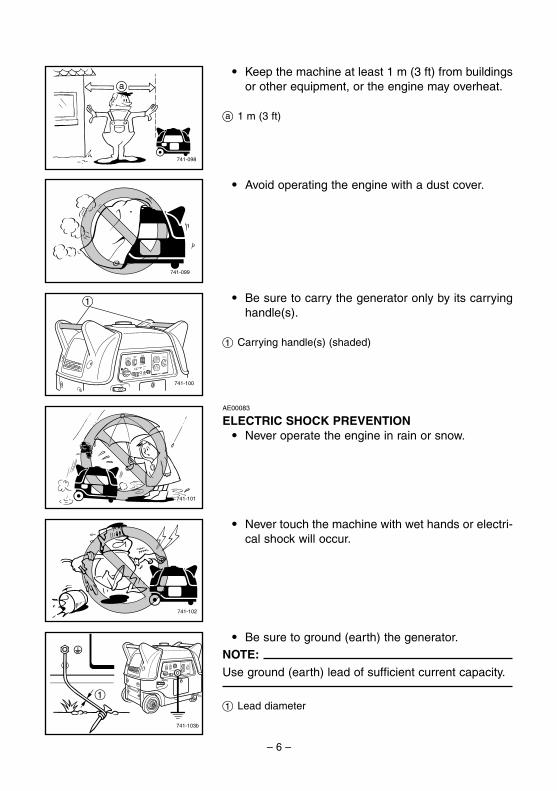
741-098
a
9 Keep the machine at least 1 m (3 ft) from buildingsor other equipment, or the engine may overheat.
a 1 m (3 ft)
741-099
9 Avoid operating the engine with a dust cover.
741-100
1 9 Be sure to carry the generator only by its carryinghandle(s).
1 Carrying handle(s) (shaded)
741-101
AE00083
ELECTRIC SHOCK PREVENTION9 Never operate the engine in rain or snow.
741-102
9 Never touch the machine with wet hands or electri-cal shock will occur.
741-103b
1
9 Be sure to ground (earth) the generator.NOTE:Use ground (earth) lead of sufficient current capacity.
1 Lead diameter
7CH-9-10-a 5/18/04 2:22 PM Page 6

– 7 –
Ground (earth) LeadDiameter:
0.12 mm (0.005 in)/ampereEX;
10 Ampere → 1.2 mm (0.05 in)
1
2
1
2
741-104
AE00088
CONNECTION NOTES9 Avoid connecting the generator to commercial
power outlet.9 Avoid connecting the generator in parallel with any
other generator.
1 Correct2 Incorrect
AE00091
CONNECTION
wBefore the generator can be connected to a build-ing’s electrical system, a licensed electrician mustinstall an isolation (transfer) switch in the build-ing’s main fuse box. The switch is the connectionpoint for generator power and allows selection ofgenerator or main line power to the building. Thiswill prevent the generator from charging the mainpower line (backfeeding) when the main power sup-ply has failed or has been turned off for line repair.Backfeeding can electrocute or injure line mainte-nance personnel. Also, generator and buildingelectrical system damage can occur when normaloperating power returns if unit is used without anisolation switch.
AE00086
EXTENSION CORD NOTES9 When using an extension cord, its total length
should not exceed60 meters for cross section of 1.5 mm squareand100 meters for cross section of 2.5 mm square.
9 This extension cord should be protected by a toughflexible rubber sheath (IEC 245) or the equivalentto withstand mechanical stresses.
7CH-9-10-a 5/18/04 2:22 PM Page 7
– 8 –
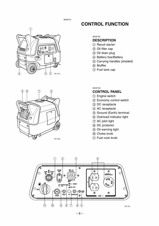
AE00101
CONTROL FUNCTION
r we
q
793-107c
t tuy
793-108c
q w e r
!1 !0 o i u 793-109ty
AE00103
CONTROL PANEL1 Engine switch2 Economy control switch3 DC receptacle4 AC receptacle5 Ground (Earth) terminal6 Overload indicator light7 AC pilot light8 DC protector9 Oil warning light0 Choke knobq Fuel cock knob
AE00102
DESCRIPTION1 Recoil starter2 Oil filler cap3 Oil drain plug4 Battery box/Battery5 Carrying handles (shaded)6 Muffler7 Fuel tank cap
7CH-9-10-a 5/18/04 2:22 PM Page 8
– 9 –
700-121
763-119
q
w e
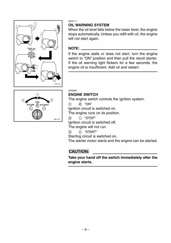
AE00111
OIL WARNING SYSTEMWhen the oil level falls below the lower level, the enginestops automatically. Unless you refill with oil, the enginewill not start again.
NOTE:If the engine stalls or does not start, turn the engineswitch to “ON” position and then pull the recoil starter.If the oil warning light flickers for a few seconds, theengine oil is insufficient. Add oil and restart.
AE00896
ENGINE SWITCHThe engine switch controls the ignition system.1 7 “ON”Ignition circuit is switched on.The engine runs on its position.2 5 “STOP”Ignition circuit is switched off.The engine will not run.3 6 “START”Starting circuit is switched on.The starter motor starts and the engine can be started.
cCTake your hand off the switch immediately after theengine starts.
7CH-9-10-a 5/18/04 2:22 PM Page 9

– 10 –
q
w
763-124a
AE00988
ECONOMY CONTROL SWITCH1 I “ON”When the economy control switch is turned “ON”, theeconomy control unit controls the engine speedaccording to the connected load. The results are betterfuel consumption and less noise.
2 3 “OFF”When the economy control switch is turned “OFF”, theengine runs at the rated r/min (3,800 r/min) regardlessof whether there is a load connected or not.
NOTE:The economy control switch must be turned to “3”(OFF) when using electric devices that require a largestarting current, such as a compressor or a submergi-ble pump.
763-231
763-238a
q
w
763-232
AE00911
DC PROTECTORThe DC protector turns off automatically when the loadexceeds the generator rated output.
cCReduce the load to the specified generator ratedoutput if the DC protector turns off. If it turns offagain, consult a Yamaha dealer.
NOTE:Press to reset the DC protector.
1 I “RESET”2 3 “OFF”
AE01048
FUEL COCK KNOBThe fuel cock knob is used to supply fuel from the fueltank to the carburetor.
7CH-9-10-a 5/18/04 2:22 PM Page 10
– 11 –
741-105
707-033a
q
707-100
707-037
707-101
AE00845
PRE-OPERATION CHECK
NOTE:Pre-operation checks should be made each time thegenerator is used.
wThe engine and muffler will be very hot after theengine has been run.Avoid touching the engine and muffler while theyare still hot with any part of your body or clothingduring inspection or repair.
AE00856
FUELMake sure there is sufficient fuel in the tank.
Your Yamaha engine has been designed to use regularunleaded gasoline with a pump octane number ((R +M)/2) of 86 or higher, or research octane number of 91or higher.
1 Fuel level gauge
w9 Fuel is highly flammable and poisonous. Check
“SAFETY INFORMATION” (See page 5) careful-ly before refueling.
9 Do not fill above the top of the fuel filter or itmay overflow when the fuel heats up later andexpands.
9 Wipe up any spilled fuel immediately.9 After refueling, make sure the tank cap is tight-
ened securely.
Recommended fuel:Unleaded gasoline
Fuel tank capacity:Total: 13.0 L (2.86 Imp gal, 3.43 US gal)
“F” Full“E” Empty
7CH-9-10-a 5/18/04 2:22 PM Page 11

– 12 –
700-122
741-106b
700-103c
q
700-065
0°C 25°C
80°F32°F
A YAMALUBE 4(10W-30)
D SAE 10W C SAE #20 B SAE #30
700-006
AE00222
ENGINE OILMake sure the engine oil is at the upper level of the oilfiller hole.Add oil as necessary.
1 Upper level
NOTE:Recommended engine oil classification:API Service “SE” or “SF”.
cCThe generator has been shipped without engine oil.Fill with oil or it will not start.
AE00241
GROUND (Earth)
Make sure to ground (earth) the generator.Check “SAFETY INFORMATION” on page 6.
Recommended oil:å YAMALUBE 4 (10W-30) or SAE 10W-30
type SE motor oil∫ SAE #30ç SAE #20∂ SAE 10W
Engine oil quantity:0.6 L (0.53 lmp qt, 0.63 US qt)
7CH-9-10-a 5/18/04 2:22 PM Page 12

– 13 –
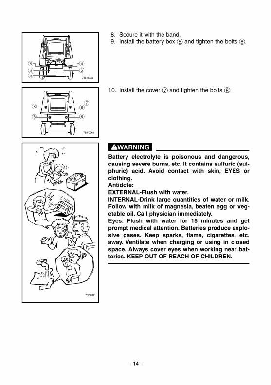
AE01083
BATTERY(See page 30)
Installation1. Loosen the bolts 1 and remove the cover 2.
2. Loosen the bolts 3 and remove the battery box 4.
3. Remove the band 5 to remove the battery 6.4. Fill the battery with the electrolyte.
Refer to the instruction sheet included with theelectrolyte for filling instructions.
5. Turn the engine switch to the “STOP” position toprevent accidental short circuiting.
6. Install the battery onto the battery box.7. Connect the positive lead 1 to the positive battery
terminal 2, then the negative lead 3 to the nega-tive battery terminal 4.
NOTE:9 Clamp the red wire to the positive (+) terminal first,
then the black wire to the negative (-) terminal ofthe battery. Do not reverse these positions.
9 For EF3000iSEB, tighten the two positive batteryleads (one from the starter relay and one from theDC-DC converter) to the same positive terminaland the two negative battery leads (one from theengine and one from the DC-DC converter) to thesame negative terminal.
788-006
wq
q
q
q
788-007
e
e
e
e
r
762-044
t
y
762-045
q
w
e
r
762-045a
to ENGINE
to STARTER RELAY
to DC-DC CONVERTER
EF3000iSEB
7CH-9-10-a 5/18/04 2:22 PM Page 13
– 14 –
8. Secure it with the band.9. Install the battery box 5 and tighten the bolts 6.
10. Install the cover 7 and tighten the bolts 8.
wBattery electrolyte is poisonous and dangerous,causing severe burns, etc. It contains sulfuric (sul-phuric) acid. Avoid contact with skin, EYES orclothing.Antidote:EXTERNAL-Flush with water.INTERNAL-Drink large quantities of water or milk.Follow with milk of magnesia, beaten egg or veg-etable oil. Call physician immediately.Eyes: Flush with water for 15 minutes and getprompt medical attention. Batteries produce explo-sive gases. Keep sparks, flame, cigarettes, etc.away. Ventilate when charging or using in closedspace. Always cover eyes when working near bat-teries. KEEP OUT OF REACH OF CHILDREN.
788-007a
y
y
y
y
t
788-006a
ui
i
i
i
762-012
7CH-9-10-a 5/18/04 2:22 PM Page 14
– 15 –
700-006a
q
761-080
763-126b
q
705-073
ON
OFF
q
763-120e
q
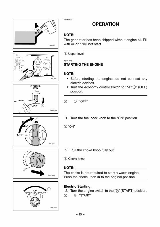
AE00955
OPERATION
NOTE:The generator has been shipped without engine oil. Fillwith oil or it will not start.
1 Upper level
AE01073
STARTING THE ENGINE
NOTE:9 Before starting the engine, do not connect any
electric devices.9 Turn the economy control switch to the “3” (OFF)
position.
1 3 “OFF”
1. Turn the fuel cock knob to the “ON” position.
1 “ON”
2. Pull the choke knob fully out.
1 Choke knob
NOTE:The choke is not required to start a warm engine.Push the choke knob in to the original position.
Electric Starting:3. Turn the engine switch to the “6” (START) position.1 6 “START”
701-049b
q
7CH-9-10-a 5/18/04 2:22 PM Page 15
– 16 –
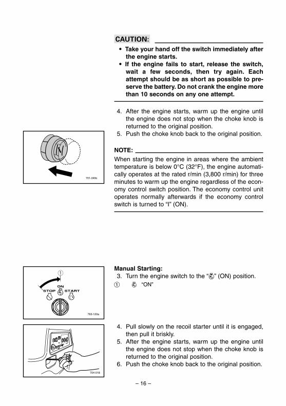
cC9 Take your hand off the switch immediately after
the engine starts.9 If the engine fails to start, release the switch,
wait a few seconds, then try again. Eachattempt should be as short as possible to pre-serve the battery. Do not crank the engine morethan 10 seconds on any one attempt.
4. After the engine starts, warm up the engine untilthe engine does not stop when the choke knob isreturned to the original position.
5. Push the choke knob back to the original position.
NOTE:When starting the engine in areas where the ambienttemperature is below 0°C (32°F), the engine automati-cally operates at the rated r/min (3,800 r/min) for threeminutes to warm up the engine regardless of the econ-omy control switch position. The economy control unitoperates normally afterwards if the economy controlswitch is turned to “I” (ON).
763-120a
q
704-018
701-049c
Manual Starting:3. Turn the engine switch to the “7” (ON) position.1 7 “ON”
4. Pull slowly on the recoil starter until it is engaged,then pull it briskly.
5. After the engine starts, warm up the engine untilthe engine does not stop when the choke knob isreturned to the original position.
6. Push the choke knob back to the original position.
7CH-9-10-a 5/18/04 2:22 PM Page 16
– 17 –
AE01000
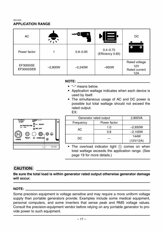
APPLICATION RANGE
AC DC
Power factor 1 0.8–0.950.4–0.75
(Efficiency 0.85)
EF3000iSE–2,800W –2,240W –950W
EF3000iSEB
Rated voltage12V
Rated current12A
NOTE:9 “–” means below.9 Application wattage indicates when each device is
used by itself.9 The simultaneous usage of AC and DC power is
possible but total wattage should not exceed therated output.EX:
9 The overload indicator light 1 comes on whentotal wattage exceeds the application range. (Seepage 19 for more details.)
cCBe sure the total load is within generator rated output otherwise generator damagewill occur.
NOTE:Some precision equipment is voltage sensitive and may require a more uniform voltagesupply than portable generators provide. Examples include some medical equipment,personal computers, and some inverters that sense peak and RMS voltage values.Consult the precision-equipment vendor before relying on any portable generator to pro-vide power to such equipment.
760-026q
Generator rated output 2,800VA
Frequency Power factor
1.0 –2,650WAC
0.8 –2,100W144W
DC —(12V/12A)
7CH-9-10-a 5/18/04 2:22 PM Page 17

– 18 –
761-081
761-082
760-027q
763-129a
q
AE01023
CONNECTION
Alternating Current (AC)
cC9 Be sure all electric devices including the lines
and plug connections are in good conditionbefore connection to the generator.
9 Be sure any electric devices are turned offbefore plugging it in.
9 Be sure the total load is within generator ratedoutput.
9 Be sure the receptacle load current is withinreceptacle rated current.
1. Wind the power lead 2 or 3 turns around handle.2. Start the engine.3. Plug in to the AC receptacle.
4. Make sure the AC pilot light is on.
1 AC pilot light
5. Turn the economy control switch to the “I” (ON)position and turn on any electric devices.
1 I (ON)
NOTE:The economy control switch must be turned to “3”(OFF) when using electric devices that require a largestarting current, such as a compressor or a submergi-ble pump.
7CH-9-10-a 5/18/04 2:22 PM Page 18
– 19 –
760-026q
AE01087
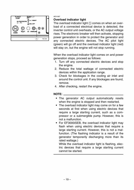
Overload indicator lightThe overload indicator light 1 comes on when an over-load of a connected electrical device is detected, theinverter control unit overheats, or the AC output voltagerises. The electronic breaker will then activate, stoppingpower generation in order to protect the generator andany connected electric devices. The AC pilot light(green) will go off and the overload indicator light (red)will stay on, but the engine will not stop running.
When the overload indicator light comes on and powergeneration stops, proceed as follows:1. Turn off any connected electric devices and stop
the engine.2. Reduce the total wattage of connected electric
devices within the application range.3. Check for blockages in the cooling air inlet and
around the control unit. If any blockages are found,remove.
4. After checking, restart the engine.
NOTE:9 The generator AC output automatically resets
when the engine is stopped and then restarted.9 The overload indicator light may come on for a few
seconds at first when using electric devices thatrequire a large starting current, such as a com-pressor or a submergible pump. However, this isnot a malfunction.
9 For EF3000iSEB, the overload indicator light mayflash when using electric devices that require alarge starting current. However, this is not a mal-function. (The flashing indicator is a result of thegenerator temporarily discharging more than itsrated wattage.)While the overload indicator light is flashing, elec-tric devices that require a large starting currentcannot be started.
7CH-9-10-a 5/18/04 2:22 PM Page 19

– 20 –
761-081a
762-042
12
12v762-043a
763-238a
q
w
AE00825
Battery Charging
NOTE:The generator DC rated voltage is 12V.
1. Wind the battery charging lead (furnished as anaccessory) 2 or 3 turns around the handle and pluginto DC receptacle.
NOTE:9 Make connections to the battery after starting the
engine.9 Clamp the red wire to the positive (+) terminal and
the black wire to the negative (-) terminal of thebattery. Do not reverse these positions.
1 Red2 Black
2. Start the engine.3. Press in the DC protector and install the battery.
cC9 Be sure the battery leads are properly connect-
ed.9 Be sure the breather hose is properly connect-
ed and is not damaged or obstructed.9 Reduce the load to the specified generator
rated output if the DC protector turns off. If itturns off again, consult a Yamaha dealer.
NOTE:Press to reset the DC protector.
1 “ON”2 “OFF”
NOTE:9 At full charge, electrolyte specific gravity is
between 1.26 and 1.28.9 Check specific gravity hourly.
7CH-9-10-a 5/18/04 2:22 PM Page 20
– 21 –
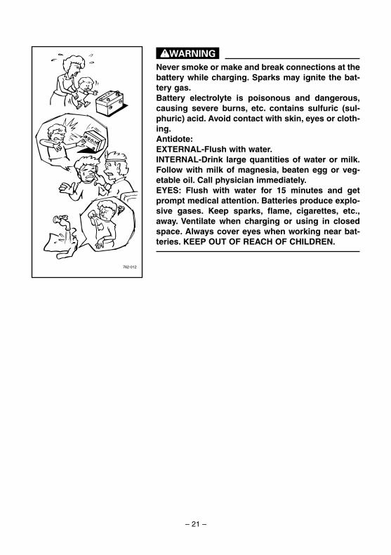
wNever smoke or make and break connections at thebattery while charging. Sparks may ignite the bat-tery gas.Battery electrolyte is poisonous and dangerous,causing severe burns, etc. contains sulfuric (sul-phuric) acid. Avoid contact with skin, eyes or cloth-ing.Antidote:EXTERNAL-Flush with water.INTERNAL-Drink large quantities of water or milk.Follow with milk of magnesia, beaten egg or veg-etable oil. Call physician immediately.EYES: Flush with water for 15 minutes and getprompt medical attention. Batteries produce explo-sive gases. Keep sparks, flame, cigarettes, etc.,away. Ventilate when charging or using in closedspace. Always cover eyes when working near bat-teries. KEEP OUT OF REACH OF CHILDREN.
762-012
7CH-9-10-a 5/18/04 2:22 PM Page 21
– 22 –
763-126b
q
761-080
763-120b
q
705-073a
ON
OFFq
AE01050
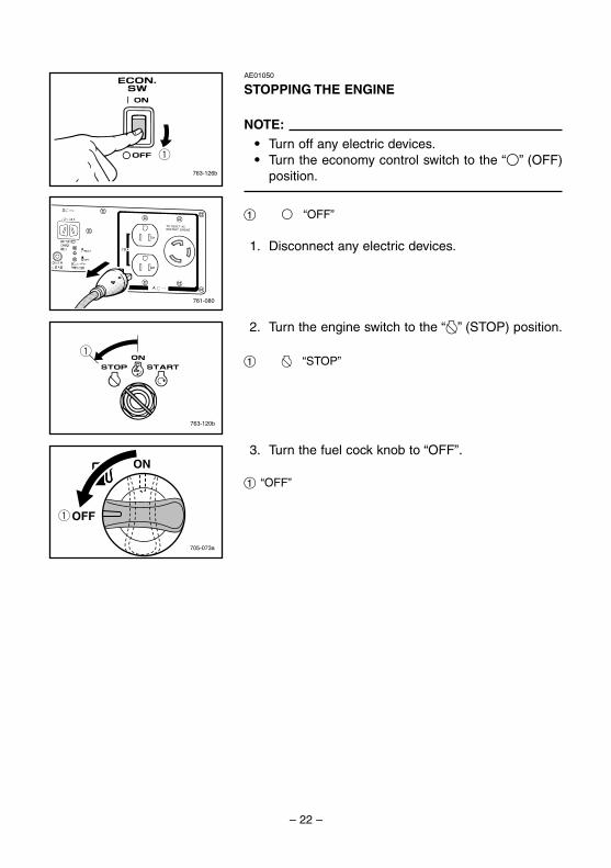
STOPPING THE ENGINE
NOTE:9 Turn off any electric devices.9 Turn the economy control switch to the “3” (OFF)
position.
1 3 “OFF”
1. Disconnect any electric devices.
2. Turn the engine switch to the “5” (STOP) position.
1 5 “STOP”
3. Turn the fuel cock knob to “OFF”.
1 “OFF”
7CH-9-10-a 5/18/04 2:22 PM Page 22
– 23 –
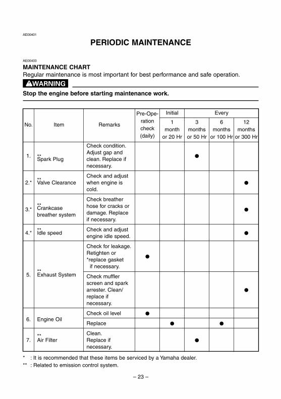
No. Item Remarks
Pre-Ope-rationcheck(daily)
Initial Every
1month
or 20 Hr
3monthsor 50 Hr
6months
or 100 Hr
12months
or 300 Hr
Check condition.
1. **Adjust gap and
0Spark Plug clean. Replace if
necessary.
**Check and adjust
2.* Valve Clearance when engine is 0
cold.
Check breather** hose for cracks or
03.* Crankcasedamage. Replacebreather systemif necessary.
4.* ** Check and adjust0Idle speed
engine idle speed.
Check for leakage.Retighten or
0*replace gasket
**if necessary.
5. Exhaust System Check mufflerscreen and sparkarrester. Clean/ 0replace ifnecessary.
Check oil level 06. Engine Oil
Replace 0 0
** Clean.7. Air Filter Replace if 0
necessary.
AE00401
PERIODIC MAINTENANCE
AE00403
MAINTENANCE CHARTRegular maintenance is most important for best performance and safe operation.
wStop the engine before starting maintenance work.
* : It is recommended that these items be serviced by a Yamaha dealer.** : Related to emission control system.
7CH-9-10-b 6/18/04 5:58 PM Page 23
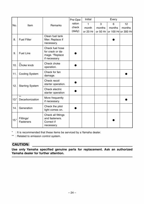
– 24 –
* : It is recommended that these items be serviced by a Yamaha dealer.** : Related to emission control system.
cCUse only Yamaha specified genuine parts for replacement. Ask an authorizedYamaha dealer for further attention.
Clean fuel tank 8. Fuel Filter filter. Replace if 0
necessary.
Check fuel hose
9. Fuel Linefor crack or da-
0mage. *Replaceif necessary.
10. ** Check choke0Choke knob
operation.
11. Cooling SystemCheck for fan
0damage.
Check recoil0
12. Starting Systemstarter operation.
Check electric 0
starter operation
13.*** More frequently
0Decarbonizationif necessary.
14. GenerationCheck the pilot
0light comes on.
Check all fittings
15.*Fittings/ and fasteners.
0Fasteners Correct if
necessary.
No. Item Remarks
Pre-Ope-rationcheck(daily)
Initial Every
1month
or 20 Hr
3monthsor 50 Hr
6months
or 100 Hr
12months
or 300 Hr
7CH-9-10-b 6/18/04 5:58 PM Page 24
– 25 –
788-003a
q
w
760-028
a
760-001a
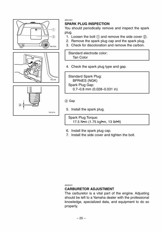
AE01051
SPARK PLUG INSPECTIONYou should periodically remove and inspect the sparkplug.1. Loosen the bolt 1 and remove the side cover 2.2. Remove the spark plug cap and the spark plug.3. Check for discoloration and remove the carbon.
4. Check the spark plug type and gap.
a Gap
5. Install the spark plug.
6. Install the spark plug cap.7. Install the side cover and tighten the bolt.
Standard electrode color:Tan Color
Standard Spark Plug:BPR4ES (NGK)
Spark Plug Gap:0.7–0.8 mm (0.028–0.031 in)
Spark Plug Torque:17.5 N•m (1.75 kgf•m, 13 lbf•ft)
AE00431
CARBURETOR ADJUSTMENTThe carburetor is a vital part of the engine. Adjustingshould be left to a Yamaha dealer with the professionalknowledge, specialized data, and equipment to do soproperly.
7CH-9-10-b 6/18/04 5:58 PM Page 25
– 26 –
788-004a
q
w
700-123b
u
yt
re
700-006a
q
700-065
0°C 25°C
80°F32°F
A YAMALUBE 4(10W-30)
D SAE 10W C SAE #20 B SAE #30
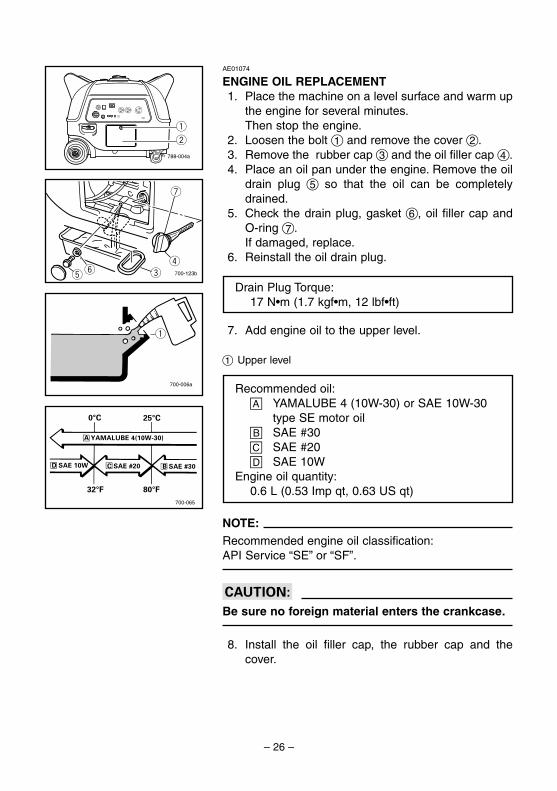
AE01074
ENGINE OIL REPLACEMENT1. Place the machine on a level surface and warm up
the engine for several minutes.Then stop the engine.
2. Loosen the bolt 1 and remove the cover 2.3. Remove the rubber cap 3 and the oil filler cap 4.4. Place an oil pan under the engine. Remove the oil
drain plug 5 so that the oil can be completelydrained.
5. Check the drain plug, gasket 6, oil filler cap andO-ring 7.If damaged, replace.
6. Reinstall the oil drain plug.
7. Add engine oil to the upper level.
1 Upper level
NOTE:Recommended engine oil classification:API Service “SE” or “SF”.
cCBe sure no foreign material enters the crankcase.
8. Install the oil filler cap, the rubber cap and thecover.
Recommended oil:å YAMALUBE 4 (10W-30) or SAE 10W-30
type SE motor oil∫ SAE #30ç SAE #20∂ SAE 10W
Engine oil quantity:0.6 L (0.53 Imp qt, 0.63 US qt)
Drain Plug Torque:17 N•m (1.7 kgf•m, 12 lbf•ft)
7CH-9-10-b 6/18/04 5:58 PM Page 26
– 27 –
741-105
788-005
711-072a
q
w
e
711-073
711-074
q
711-075
AE01075
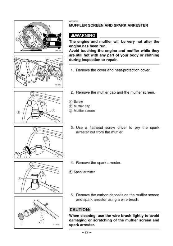
MUFFLER SCREEN AND SPARK ARRESTER
wThe engine and muffler will be very hot after theengine has been run.Avoid touching the engine and muffler while theyare still hot with any part of your body or clothingduring inspection or repair.
1. Remove the cover and heat-protection cover.
2. Remove the muffler cap and the muffler screen.
1 Screw2 Muffler cap3 Muffler screen
3. Use a flathead screw driver to pry the sparkarrester out from the muffler.
4. Remove the spark arrester.
1 Spark arrester
5. Remove the carbon deposits on the muffler screenand spark arrester using a wire brush.
cCWhen cleaning, use the wire brush lightly to avoiddamaging or scratching of the muffler screen andspark arrester.
7CH-9-10-b 6/18/04 5:58 PM Page 27

– 28 –
6. Check the muffler screen and spark arrester.Replace them if damaged.
7. Install the spark arrester.
NOTE:Align the spark arrester projection with the hole in themuffler pipe.
1 Projection2 Hole
8. Install the muffler screen and the muffler cap.
711-076
q
w
711-077
788-012
2
1
788-013
4
3
710-061a
AE01084
AIR FILTER1. Loosen the bolt 1 and remove the cover 2.
2. Remove the clip 3 holding the air filter cover 4.3. Remove the air filter cover and element.
4. Wash the foam element in solvent and dry.5. Oil the foam element and squeeze out excess oil.
The foam element should be wet but not dripping.
Recommended oil:Foam-air-filter oil
orSAE #20 motor oil
7CH-9-10-b 6/18/04 5:58 PM Page 28
– 29 –
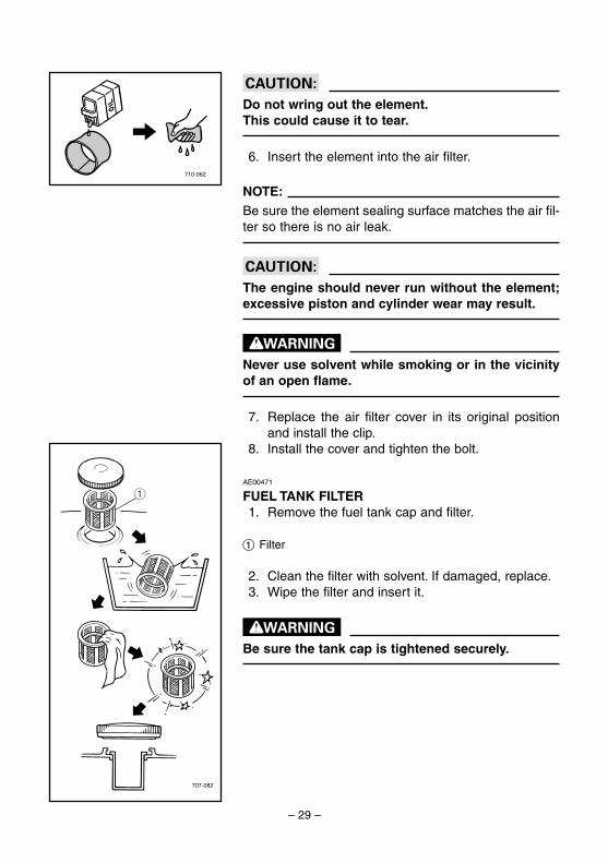
cCDo not wring out the element.This could cause it to tear.
6. Insert the element into the air filter.
NOTE:Be sure the element sealing surface matches the air fil-ter so there is no air leak.
cCThe engine should never run without the element;excessive piston and cylinder wear may result.
wNever use solvent while smoking or in the vicinityof an open flame.
7. Replace the air filter cover in its original positionand install the clip.
8. Install the cover and tighten the bolt.
710-062
707-082
qAE00471
FUEL TANK FILTER1. Remove the fuel tank cap and filter.
1 Filter
2. Clean the filter with solvent. If damaged, replace.3. Wipe the filter and insert it.
wBe sure the tank cap is tightened securely.
7CH-9-10-b 6/18/04 5:58 PM Page 29
– 30 –
762-012
AE01085
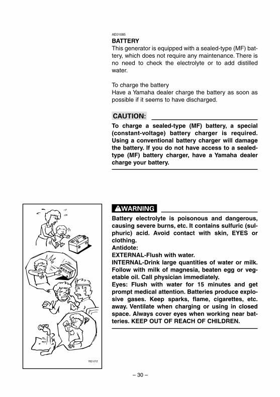
BATTERYThis generator is equipped with a sealed-type (MF) bat-tery, which does not require any maintenance. There isno need to check the electrolyte or to add distilledwater.
To charge the batteryHave a Yamaha dealer charge the battery as soon aspossible if it seems to have discharged.
cCTo charge a sealed-type (MF) battery, a special(constant-voltage) battery charger is required.Using a conventional battery charger will damagethe battery. If you do not have access to a sealed-type (MF) battery charger, have a Yamaha dealercharge your battery.
wBattery electrolyte is poisonous and dangerous,causing severe burns, etc. It contains sulfuric (sul-phuric) acid. Avoid contact with skin, EYES orclothing.Antidote:EXTERNAL-Flush with water.INTERNAL-Drink large quantities of water or milk.Follow with milk of magnesia, beaten egg or veg-etable oil. Call physician immediately.Eyes: Flush with water for 15 minutes and getprompt medical attention. Batteries produce explo-sive gases. Keep sparks, flame, cigarettes, etc.away. Ventilate when charging or using in closedspace. Always cover eyes when working near bat-teries. KEEP OUT OF REACH OF CHILDREN.
7CH-9-10-b 6/18/04 5:58 PM Page 30

– 31 –
779-070a
788-008
q
w
AE01077
FUSE REPLACEMENT
wBe sure to use specified fuse. A wrong fuse willcause electrical system damage and A FIRE HAZ-ARD.
cCBe sure the engine switch is turned to “STOP” toprevent accidental short circuiting.
1. Remove the side cover 1 and the battery box 2.(See page 30; “BATTERY”.)
2. Replace the blown fuse with one of proper amper-age.
NOTE:If the fuse immediately blows again, consult a Yamahadealer.
Specified fuse: 10 A
7CH-9-10-b 6/18/04 5:58 PM Page 31
– 32 –
707-100
705-073b
ON
OFF
700-006
763-120g
760-009
AE01078
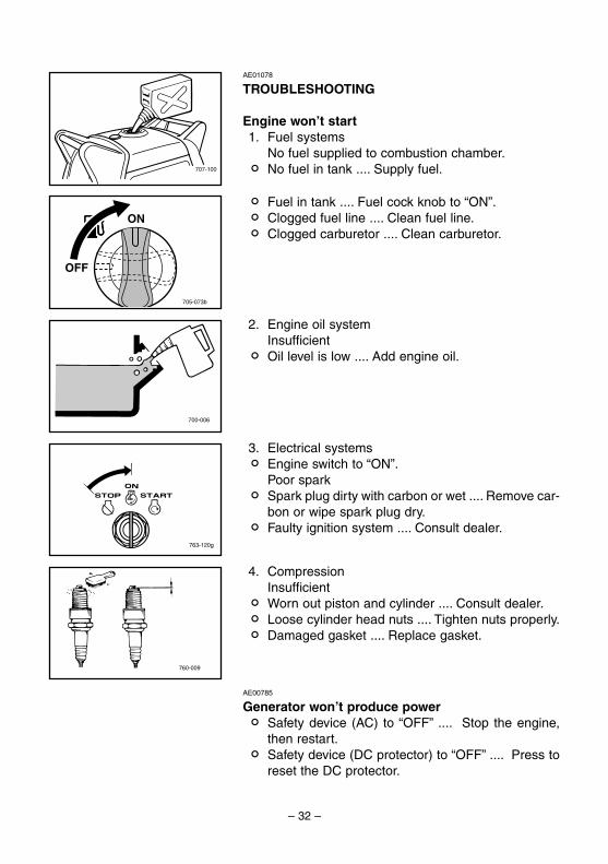
TROUBLESHOOTING
Engine won’t start1. Fuel systems
No fuel supplied to combustion chamber.2 No fuel in tank .... Supply fuel.
2. Engine oil systemInsufficient
2 Oil level is low .... Add engine oil.
3. Electrical systems2 Engine switch to “ON”.
Poor spark2 Spark plug dirty with carbon or wet .... Remove car-
bon or wipe spark plug dry.2 Faulty ignition system .... Consult dealer.
4. CompressionInsufficient
2 Worn out piston and cylinder .... Consult dealer.2 Loose cylinder head nuts .... Tighten nuts properly.2 Damaged gasket .... Replace gasket.
AE00785
Generator won’t produce power2 Safety device (AC) to “OFF” .... Stop the engine,
then restart.2 Safety device (DC protector) to “OFF” .... Press to
reset the DC protector.
2 Fuel in tank .... Fuel cock knob to “ON”.2 Clogged fuel line .... Clean fuel line.2 Clogged carburetor .... Clean carburetor.
7CH-9-10-b 6/18/04 5:58 PM Page 32
– 33 –
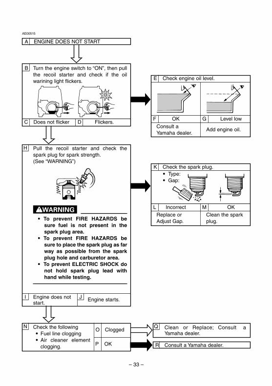
P OK
O Clogged
Engine does notstart.
C Does not flicker D Flickers.
B
AE00515
A ENGINE DOES NOT START
Turn the engine switch to “ON”, then pullthe recoil starter and check if the oilwarining light flickers.
H Pull the recoil starter and check thespark plug for spark strength.(See “WARNING”)
w9 To prevent FIRE HAZARDS be
sure fuel is not present in thespark plug area.
9 To prevent FIRE HAZARDS besure to place the spark plug as farway as possible from the sparkplug hole and carburetor area.
9 To prevent ELECTRIC SHOCK donot hold spark plug lead withhand while testing.
Engine starts.I J
Check the following9 Fuel line clogging9 Air cleaner element
clogging.
N Clean or Replace; Consult a Yamaha dealer.
Q
R Consult a Yamaha dealer.
K Check the spark plug.9 Type:9 Gap:
L Incorrect M OK
Replace orAdjust Gap.
Clean the sparkplug.
E Check engine oil level.
F OK G Level low
Consult aYamaha dealer.
Add engine oil.
7CH-9-10-b 6/18/04 5:58 PM Page 33
– 34 –
707-102a
q
712-028a
AE00601
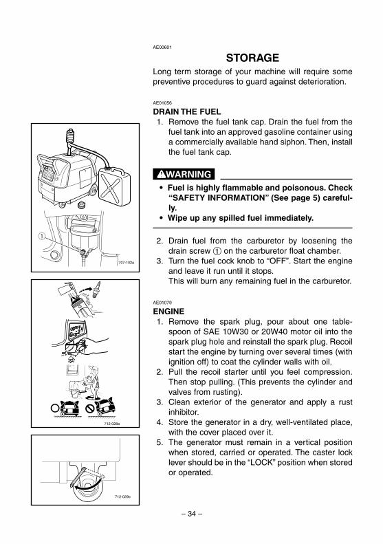
STORAGELong term storage of your machine will require somepreventive procedures to guard against deterioration.
AE01056
DRAIN THE FUEL1. Remove the fuel tank cap. Drain the fuel from the
fuel tank into an approved gasoline container usinga commercially available hand siphon. Then, installthe fuel tank cap.
w9 Fuel is highly flammable and poisonous. Check
“SAFETY INFORMATION” (See page 5) careful-ly.
9 Wipe up any spilled fuel immediately.
2. Drain fuel from the carburetor by loosening thedrain screw 1 on the carburetor float chamber.
3. Turn the fuel cock knob to “OFF”. Start the engineand leave it run until it stops.This will burn any remaining fuel in the carburetor.
AE01079
ENGINE1. Remove the spark plug, pour about one table-
spoon of SAE 10W30 or 20W40 motor oil into thespark plug hole and reinstall the spark plug. Recoilstart the engine by turning over several times (withignition off) to coat the cylinder walls with oil.
2. Pull the recoil starter until you feel compression.Then stop pulling. (This prevents the cylinder andvalves from rusting).
3. Clean exterior of the generator and apply a rustinhibitor.
4. Store the generator in a dry, well-ventilated place,with the cover placed over it.
5. The generator must remain in a vertical positionwhen stored, carried or operated. The caster locklever should be in the “LOCK” position when storedor operated.
712-029b
7CH-9-10-b 6/18/04 5:58 PM Page 34

– 35 –
762-003
AE01086
BATTERY1. Remove the battery.2. Store the battery in a cool, dark and dry place and
charge it once a month.
Do not store the battery in an excessively warm or coldplace [i.e., less than 0°C (30°F) or more than 30°C(90°F)].
w9 Disconnect the negative lead first, then the pos-
itive lead from the battery.9 Connect the positive lead first, then the nega-
tive lead to the battery when installing the bat-tery.
9 Be sure the battery terminals are tight.
cC9 Do not disconnect the battery during engine
operation.9 Avoid operating the generator with the battery
removed.
AE01057
RECOMMENDED BATTERY
NOTE:9 Clamp the red wire to the positive (+) terminal and
the black wire to the negative (-) terminal of thebattery. Do not reverse these positions.
9 Be sure the battery is installed on the battery box.
Recommended battery:Capacity: 12V/10A•h
7CH-9-10-b 6/18/04 5:58 PM Page 35
– 36 –
AE00789
EXHAUST EMISSION CONTROL SYSTEMAND COMPONENTS
Item Acronym9 CARB. ASSY., LH. & JT., .......................CARB (Carburetor)
CARBURETOR29 T.C.I. MAGNETO ASSY. & ....................EI (Electronic Ignition)
PLUG, SPARK9 CRANKCASE1 & HEAD, .......................PCV (Positive Crankcase
CYLINDER1 Ventilation)9 AIR FILTER ASSY. .................................ACL (Air Cleaner)9 MUFF., 2, CAP, NET, WIRE2 &
ARRESTER, SPARK
The above items and the corresponding acronyms are provided in accordance with U.S.EPA REGULATIONS FOR NEW NONROAD SPARK-IGNITION NONHANDHELDENGINES and the CALIFORNIA REGULATIONS FOR 1995 AND LATER SMALL OFF-ROAD ENGINES.The acronyms conform to the latest version of the SAE’s recommended practice docu-ment J1930, “Diagnostic Acronyms, Terms, and Definitions For Electrical/ElectronicSystem”.
It is recommended that these items be serviced by a Yamaha dealer.
7CH-9-10-b 6/18/04 5:58 PM Page 36
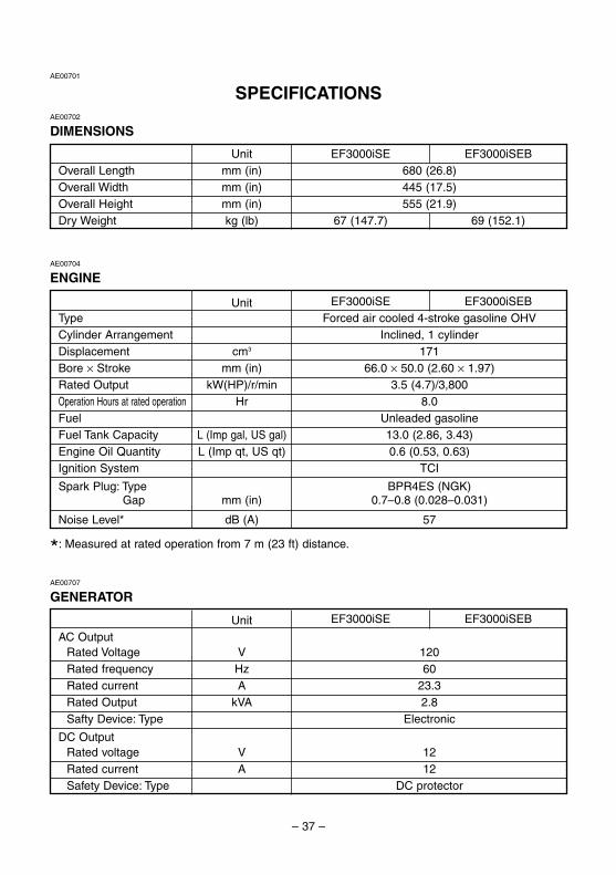
– 37 –
Unit EF3000iSE EF3000iSEBType Forced air cooled 4-stroke gasoline OHVCylinder Arrangement Inclined, 1 cylinderDisplacement cm3 171Bore × Stroke mm (in) 66.0 × 50.0 (2.60 × 1.97)Rated Output kW(HP)/r/min 3.5 (4.7)/3,800Operation Hours at rated operation Hr 8.0Fuel Unleaded gasolineFuel Tank Capacity L (Imp gal, US gal) 13.0 (2.86, 3.43)Engine Oil Quantity L (Imp qt, US qt) 0.6 (0.53, 0.63)Ignition System TCI
Spark Plug: Type BPR4ES (NGK)Spark Plug: Gap mm (in) 0.7–0.8 (0.028–0.031)
Noise Level* dB (A) 57
Unit EF3000iSE EF3000iSEB
AC OutputRated Voltage V 120Rated frequency Hz 60Rated current A 23.3Rated Output kVA 2.8Safty Device: Type Electronic
DC OutputRated voltage V 12Rated current A 12Safety Device: Type DC protector
Unit EF3000iSE EF3000iSEBOverall Length mm (in) 680 (26.8)Overall Width mm (in) 445 (17.5)Overall Height mm (in) 555 (21.9)Dry Weight kg (lb) 67 (147.7) 69 (152.1)
AE00701
SPECIFICATIONSAE00702
DIMENSIONS
AE00704
ENGINE
AE00707
GENERATOR
*: Measured at rated operation from 7 m (23 ft) distance.
7CH-9-10-b 6/18/04 5:58 PM Page 37
– 38 –– 38 –
YYY
G
O
Y
L
R
O
Y
B/W
R
O
B
G/Y R/W
B/W
B
R
R R
RR
R RR
M
R
B
L
L
L
L
BRR R
R R
R
G
GG
O
O
OO
O O
O
OO
O
O
OB/WO
OO
Y
YYY
Y
Y
Y
YY
Y
Y
L
LL
LO
OOL
LL
W
WW
W
B
B
W
R/W
G/Y
G/Y
G/Y
G/Y
G/Y
G/Y
G/Y
B/W
B/W
B/W
B/W
B/WR/W
R/W
B/W
BB/W
B/W
R
RR
R RB B
R
Br
Br
Br Br
Br
Br Br
OFF
ONSTART
770-052
q
rw
e
t
@0
!7
!6
i
!4
!1
!0
o
u u
y
@1
@2
!2
!3
!5!8
!9
@3
@4
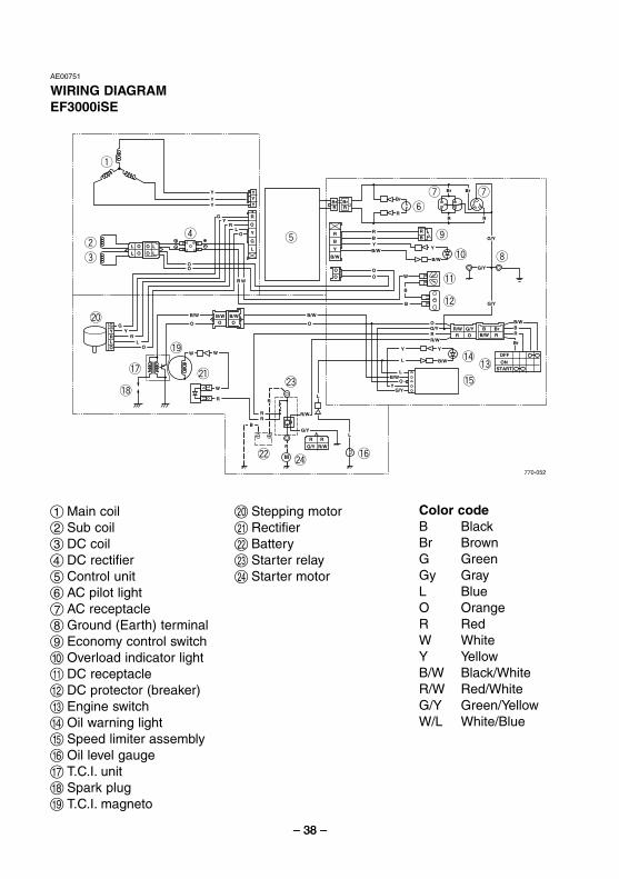
AE00751
WIRING DIAGRAMEF3000iSE
1 Main coil2 Sub coil3 DC coil4 DC rectifier5 Control unit6 AC pilot light7 AC receptacle8 Ground (Earth) terminal9 Economy control switch0 Overload indicator lightq DC receptaclew DC protector (breaker)e Engine switchr Oil warning lightt Speed limiter assemblyy Oil level gaugeu T.C.I. uniti Spark plugo T.C.I. magneto
p Stepping motora Rectifiers Batteryd Starter relayf Starter motor
Color codeB BlackBr BrownG GreenGy GrayL BlueO OrangeR RedW WhiteY YellowB/W Black/WhiteR/W Red/WhiteG/Y Green/YellowW/L White/Blue
7CH-9-10-b 6/18/04 5:58 PM Page 38
– 39 –
770-052a
G/Y R/W
B/W
B
R
R
R R
R
R R
R
M
R
RR
B
B
L
L
L
L
BRR R
R R
R
G
G
G
G
GG
O
O
O
OO
O O
O
OO O
O
O
OB/WO
OO
Y
Y
Y
Y
Y
YY
Y
Y
Y
YYY
L
L
RGL
L
L
LL
LO
OOL
LL
W
WW
W
B
B
W
R/W
G/Y
G/Y
G/Y
G/Y
G/Y
G/Y
G/Y
B/W
B/W
B/W
B/W
B/WR/W
R/W
B/W
BB/W
B/WB/W
R
RR
RR
O
RB
R
BB
R
Br
Br
Br Br
Br
BrBrBr Br
OFF
ONSTART
R
RR
R
GL
R
Br
q
rw
e
@1
@2
@3
@4
t
@0!9
!6
!7!5
i
!3
!2
!8
!4
!1
!0
o
u u
y
@5
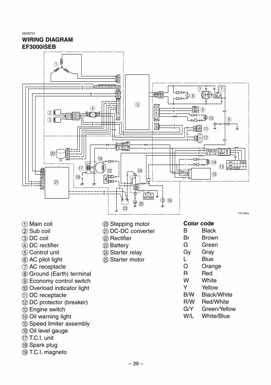
AE00751
WIRING DIAGRAMEF3000iSEB
1 Main coil2 Sub coil3 DC coil4 DC rectifier5 Control unit6 AC pilot light7 AC receptacle8 Ground (Earth) terminal9 Economy control switch0 Overload indicator lightq DC receptaclew DC protector (breaker)e Engine switchr Oil warning lightt Speed limiter assemblyy Oil level gaugeu T.C.I. uniti Spark plugo T.C.I. magneto
p Stepping motora DC-DC converters Rectifierd Batteryf Starter relayg Starter motor
Color codeB BlackBr BrownG GreenGy GrayL BlueO OrangeR RedW WhiteY YellowB/W Black/WhiteR/W Red/WhiteG/Y Green/YellowW/L White/Blue
7CH-9-10-b 6/18/04 5:58 PM Page 39

Generator
LIT-19626-01-20 7CH-28199-10PRINTED ON RECYCLED PAPERPRINTED IN JAPAN04 906 – 0.4 × 1 !
EF3000iSEEF3000iSEB
OWNER’S MANUAL
7CH-9-10 hyoshi 4/22/04 10:20 AM Page 1