Embed Size (px)
Citation preview
EFD1000 (Pilot) Airplane Flight Manual Supplement
TABLE OF CONTENTS 1 GENERAL............................................................................................................................................5
1.1 SYSTEM OVERVIEW........................................................................................................................5 2 LIMITATIONS.......................................................................................................................................6
2.1 SOFTWARE VERSIONS....................................................................................................................6 2.2 AIRSPEED LIMITATIONS ..................................................................................................................6 2.3 WEIGHT & CENTER OF GRAVITY LIMITS...........................................................................................6 2.4 RSM GPS USAGE .........................................................................................................................6 2.5 GEOGRAPHIC LIMITATION ...............................................................................................................6 2.6 PLACARDS AND DECALS .................................................................................................................7 2.7 SEAPLANE OPERATION...................................................................................................................7
3 EMERGENCY AND ABNORMAL PROCEDURES.............................................................................8 3.1 IN-FLIGHT AHRS RESET ................................................................................................................8 3.2 PITOT/STATIC SYSTEM BLOCKAGE..................................................................................................8 3.3 LOSS OF EXTERNAL POWER ...........................................................................................................9 3.4 POWER OVERRIDE .........................................................................................................................9 3.5 ABNORMAL SHUTDOWN PROCEDURE ............................................................................................10 3.6 WARNING, CAUTION, AND ADVISORY SUMMARY.............................................................................10
4 NORMAL PROCEDURES .................................................................................................................12 4.1 EXTERIOR INSPECTION .................................................................................................................12 4.2 BEFORE TAXI CHECKS..................................................................................................................12 4.3 BEFORE TAKE-OFF CHECKS.........................................................................................................12 4.4 SHUTDOWN CHECKS ....................................................................................................................12
5 PERFORMANCE ...............................................................................................................................13 6 SYSTEM DESCRIPTION ...................................................................................................................14
6.1 GENERAL.....................................................................................................................................14 6.2 PILOT CONTROLS.........................................................................................................................14 6.3 PRIMARY FLIGHT INSTRUMENTS....................................................................................................21 6.4 SITUATIONAL AWARENESS MAP DISPLAY ......................................................................................27 6.5 MAIN MENU OPERATION...............................................................................................................30 6.6 LIST OF ACRONYMS......................................................................................................................33
DOCUMENT # A-01-179-00 PAGE 3 OF 33 REVISION D FAA APPROVED Date: Feb. 3, 2009 © Copyright 2009 Aspen Avionics Inc.

EFD1000 (Pilot) Airplane Flight Manual Supplement
INTENTIONALLY LEFT BLANK
DOCUMENT # A-01-179-00 PAGE 4 OF 33 REVISION D FAA APPROVED Date: Feb. 3, 2009 © Copyright 2009 Aspen Avionics Inc.
EFD1000 (Pilot) Airplane Flight Manual Supplement
1 General
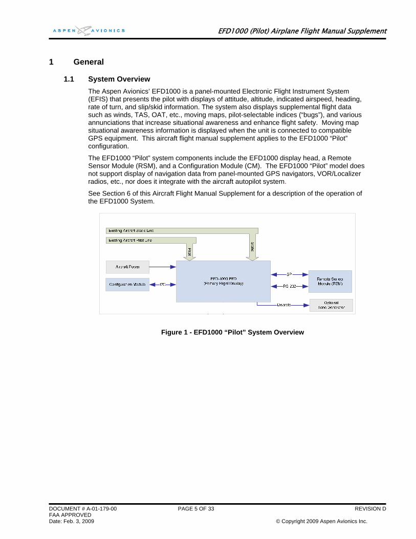
1.1 System Overview The Aspen Avionics’ EFD1000 is a panel-mounted Electronic Flight Instrument System (EFIS) that presents the pilot with displays of attitude, altitude, indicated airspeed, heading, rate of turn, and slip/skid information. The system also displays supplemental flight data such as winds, TAS, OAT, etc., moving maps, pilot-selectable indices (“bugs”), and various annunciations that increase situational awareness and enhance flight safety. Moving map situational awareness information is displayed when the unit is connected to compatible GPS equipment. This aircraft flight manual supplement applies to the EFD1000 “Pilot” configuration.
The EFD1000 “Pilot” system components include the EFD1000 display head, a Remote Sensor Module (RSM), and a Configuration Module (CM). The EFD1000 “Pilot” model does not support display of navigation data from panel-mounted GPS navigators, VOR/Localizer radios, etc., nor does it integrate with the aircraft autopilot system.
See Section 6 of this Aircraft Flight Manual Supplement for a description of the operation of the EFD1000 System.
Figure 1 - EFD1000 “Pilot” System Overview
DOCUMENT # A-01-179-00 PAGE 5 OF 33 REVISION D FAA APPROVED Date: Feb. 3, 2009 © Copyright 2009 Aspen Avionics Inc.
EFD1000 (Pilot) Airplane Flight Manual Supplement
2 Limitations
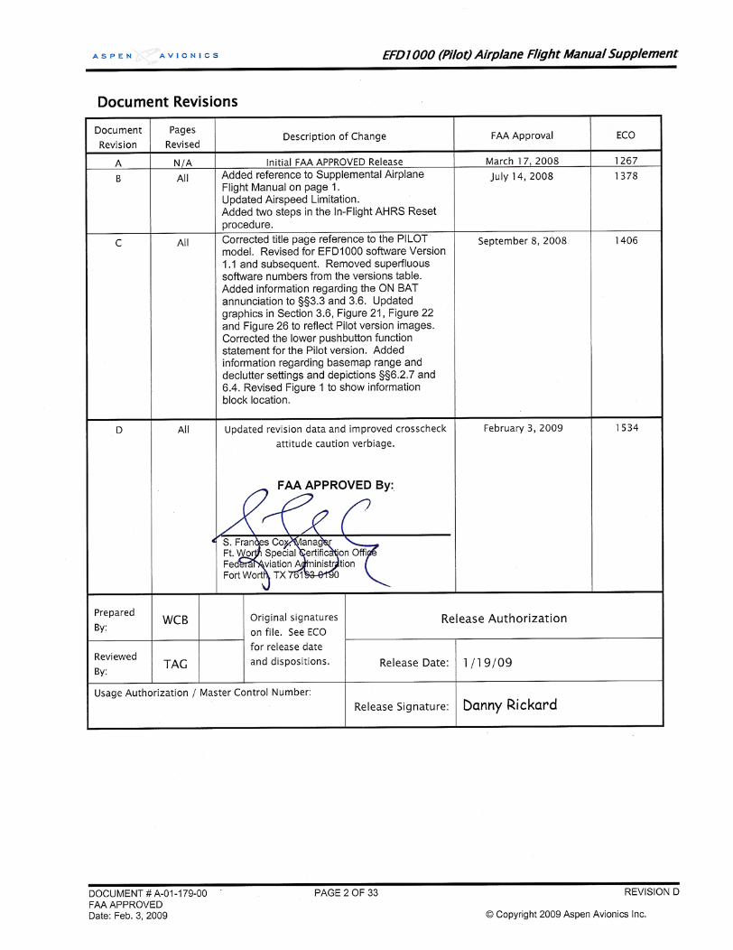
2.1 Software Versions The EFD1000 System must utilize the software versions listed below (or later FAA-approved versions). The system software version for the Main Application Processor (MAP) and for the Input-Output Processor (IOP), both of which are contained within the EFD display head, is displayed via the Main menu SYSTEM STATUS page.
Software Name Version AFM Supplement Revision IOP SOFTWARE RELEASE 1.0 A-01-179-00 Revision B or C
Or IOP SOFTWARE RELEASE 1.1 A-01-179-00 Revision C
2.2 Airspeed Limitations The maximum approved operating airspeed for this system is 264 KTS (304 MPH).
2.3 Weight & Center of Gravity Limits Installation of the EFD1000 system may result in a small net change to the aircraft empty weight and associated moment arm. Refer to the revised weight and balance records carried in the aircraft for details.
2.4 RSM GPS Usage The EFD1000 RSM GPS is authorized for emergency use only. Position data from the RSM GPS will ONLY be presented following the loss or failure of a certified external GPS navigator.
NOTE:
When the RSM GPS is in use, magnetic variation data used by the basemap is not updated. This can result in misaligned basemap
symbology whenever the external GPS position source is lost and the aircraft travels far enough to produce a significant change in
the local magnetic variation.
2.5 Geographic Limitation Like all compass systems, the magnetometer used in the EFD1000 system will experience degraded performance in the vicinity of the magnetic poles. When the horizontal component of the earth’s magnetic field is no longer strong enough to provide reliable heading data, the EFD1000 System will present a “CROSS CHECK ATTITUDE” annunciation, and will subsequently flag the magnetometer data as invalid, resulting in the annunciated loss of heading and attitude. Depending on the aircraft latitude and longitude, this effect could be observed as far away as 750 nm from the magnetic pole. In the Northern Hemisphere, this equates to operations in the Arctic Islands found north of continental North America
Use of the EFD1000 system for IFR operations with in 750 nautical miles of the Magnetic Poles, based solely upon the attitude and heading data provided by the EFD1000, is prohibited.
DOCUMENT # A-01-179-00 PAGE 6 OF 33 REVISION D FAA APPROVED Date: Feb. 3, 2009 © Copyright 2009 Aspen Avionics Inc.
EFD1000 (Pilot) Airplane Flight Manual Supplement
2.6 Placards and Decals The following electronic placard is provided on the EFD1000 display whenever the RSM GPS is providing position data for the basemap display:
“RSM GPS REVERSION EMER USE ONLY”
2.7 Seaplane Operation The EFD1000 system may not be able to align when on water as a function of the wave action being experienced by the aircraft. When aligning on water, always perform a visual verification of the attitude reference with a secondary source, such as a mechanical gyro or the horizon. If the alignment is not successful, it is acceptable to depart under VFR/VMC and, while maintaining VFR/VMC, perform an AHRS in flight alignment per section 3.
DOCUMENT # A-01-179-00 PAGE 7 OF 33 REVISION D FAA APPROVED Date: Feb. 3, 2009 © Copyright 2009 Aspen Avionics Inc.
EFD1000 (Pilot) Airplane Flight Manual Supplement
3 Emergency and Abnormal Procedures
3.1 In-Flight AHRS Reset ATTITUDE ................................................................Maintain straight and level flight
MENU........................................................................Select “GENERAL SETTINGS” Page
FLY BY VISUAL REFERENCE, OR BY STANDBY INSTRUMENTS
DISCONNECT THE AUTOPILOT
“AHRS: RESET?” LINE SELECT KEY......................PRESS
“AHRS: RESET?” LINE SELECT KEY......................PRESS AGAIN TO CONFIRM RESET
NOTE:
When the EFD1000 AHRS is reset in flight, it performs an abbreviated initialization.
During the initialization, the aircraft should not be subjected to excessive turn rates. Typical in-flight initialization will take
approximately 30 seconds, but can take longer if the reset is initiated while banked or maneuvering.
The AHRS reset is considered complete when the EFD1000 attitude and heading is once again displayed, stable, and correct
with respect to the horizon or standby indicator.
3.2 Pitot/Static System Blockage CAUTION:
Most light aircraft have only a single pitot and static port available for flight instrument use. As such, the pitot and static lines used by the EFD1000 system are shared with those lines used by the
standby airspeed indicator and altimeter. Should these lines become blocked, such as might occur due to inadvertent icing
encounter, both the standby indicators and the EFD1000 indicators will display erroneous airspeed and/or altitude
information.
Because the EFD1000 uses pitot and static pressures as part of the ADAHRS solution, loss or corruption of this data, such as
from a line blockage, will impact the accuracy of data output by the ADAHRS. Affected parameters can include the airspeed, altitude and attitude information displayed by the EFD1000.
If erroneous pitot or static inputs are detected by the EFD1000, the EFD1000 will present a “CROSS CHECK ATTITUDE”
annunciation.
A static line blockage will result in altitude remaining fixed and a zero vertical speed despite aircraft pitch and/or power setting changes. In addition, IAS indications will be incorrect if the static line is blocked. Errors will typically be noticed in the climb or descent phase of flight. When descending, ambient pressure increases which will result in the indicated airspeed reading less than the actual airspeed. The opposite effect will be observed in a climb. A static line blockage can also affect the EFD1000 attitude indication.
DOCUMENT # A-01-179-00 PAGE 8 OF 33 REVISION D FAA APPROVED Date: Feb. 3, 2009 © Copyright 2009 Aspen Avionics Inc.
EFD1000 (Pilot) Airplane Flight Manual Supplement
A pitot line blockage will result in the airspeed indicator behaving like an altimeter when the aircraft altitude changes, and it would not respond to airspeed changes. A pitot line blockage can also affect the EFD1000 attitude indication.
If a blocked pitot or static line is suspected, take the following actions:
ALTERNATE STATIC SOURCE...............................SELECT PITOT HEAT .............................................................ON
3.3 Loss of External Power In the event that external power to the unit fails, the EFD1000 will automatically switch to its internal battery.
When operating on internal battery, the display backlight intensity is capped at a value of 70.
SW Version 1.0: Refer to the Main Menu - Power Settings Page when operating on battery to determine the estimated battery charge remaining.
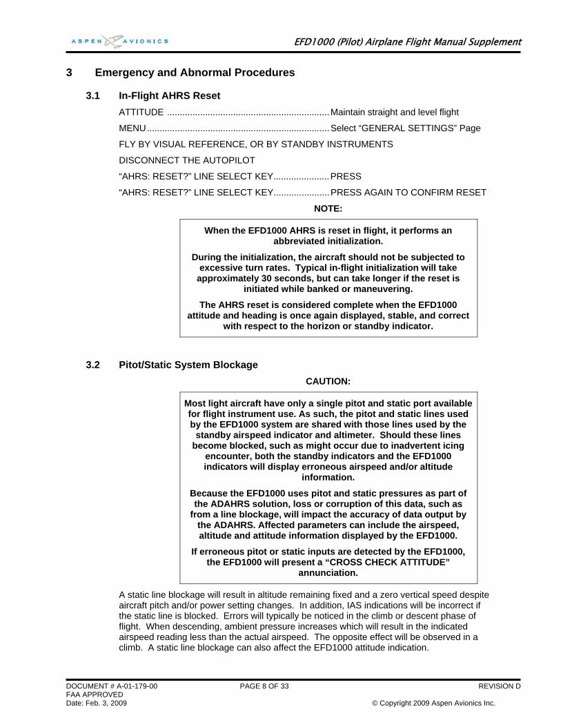
SW Version 1.1 and subsequent: An annunciation of this operating state and the estimated battery charge remaining is displayed in the lower portion of the attitude indicator.
CAUTION:
During situations where a high electrical demand is placed on the aircraft electrical system, electrical transients that cause aircraft
voltage to momentarily drop below 12.5±0.3V (14V Electrical System) or 25.0±0.6V (28V Electrical System) will cause the EFD
to automatically switch to its internal battery.
This will be accompanied by an “ON BAT” annunciation.
The “ON BAT” annunciation should extinguish shortly after the electric transient demand goes away. If the “ON BAT”
annunciation does not extinguish then an external power source failure has most likely occurred
NOTE:
When fully charged the EFD1000 internal battery will allow for operation for the AHRS, display and RSM emergency GPS for at
least 30 minutes.
3.4 Power Override In the event that the pilot wishes to override the automatic power configuration of the equipment:
MENU................................................................................ Select “POWER SETTINGS” Page
To switch FROM External Power TO Battery:
“BATTERY” LINE SELECT KEY....................................... PRESS
To switch FROM Battery TO External Power:
“EXT PWR” LINE SELECT KEY ....................................... PRESS
DOCUMENT # A-01-179-00 PAGE 9 OF 33 REVISION D FAA APPROVED Date: Feb. 3, 2009 © Copyright 2009 Aspen Avionics Inc.
EFD1000 (Pilot) Airplane Flight Manual Supplement
NOTE:
When airborne, if the EFIS input voltage is below the 12.5±0.3V (14V Electrical System) or 25.0±0.6V (28V Electrical System)
automatic battery transition threshold, and “EXT PWR” is selected the EFD will automatically transition back to its internal
battery.
3.5 Abnormal Shutdown Procedure Circuit Breaker................................................................... PULL
REV Button........................................................................ HOLD UNTIL DISPLAY BLANKS
3.6 Warning, Caution, and Advisory Summary
WARNINGS ON BAT (SW Version 1.1 and subsequent)
Red annunciation presented whenever the EFD1000 is operating on the internal battery. Will be accompanied by an indication of the estimated battery charge remaining.
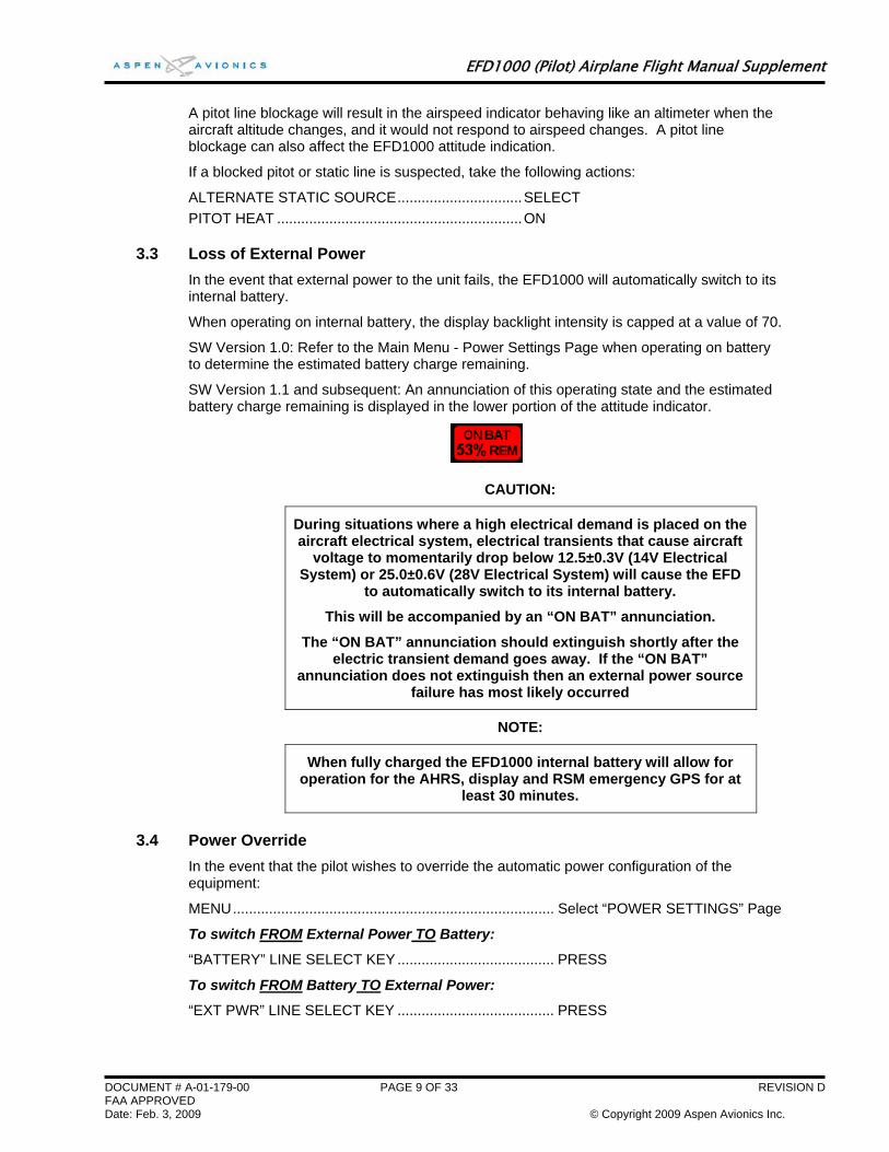
Function FAIL (“X”)
Red annunciation presented whenever the EFD1000 has determined that the associated function is invalid or failed and should not be used. The data is removed from the display and replaced by a red “X” over the affected display feature.
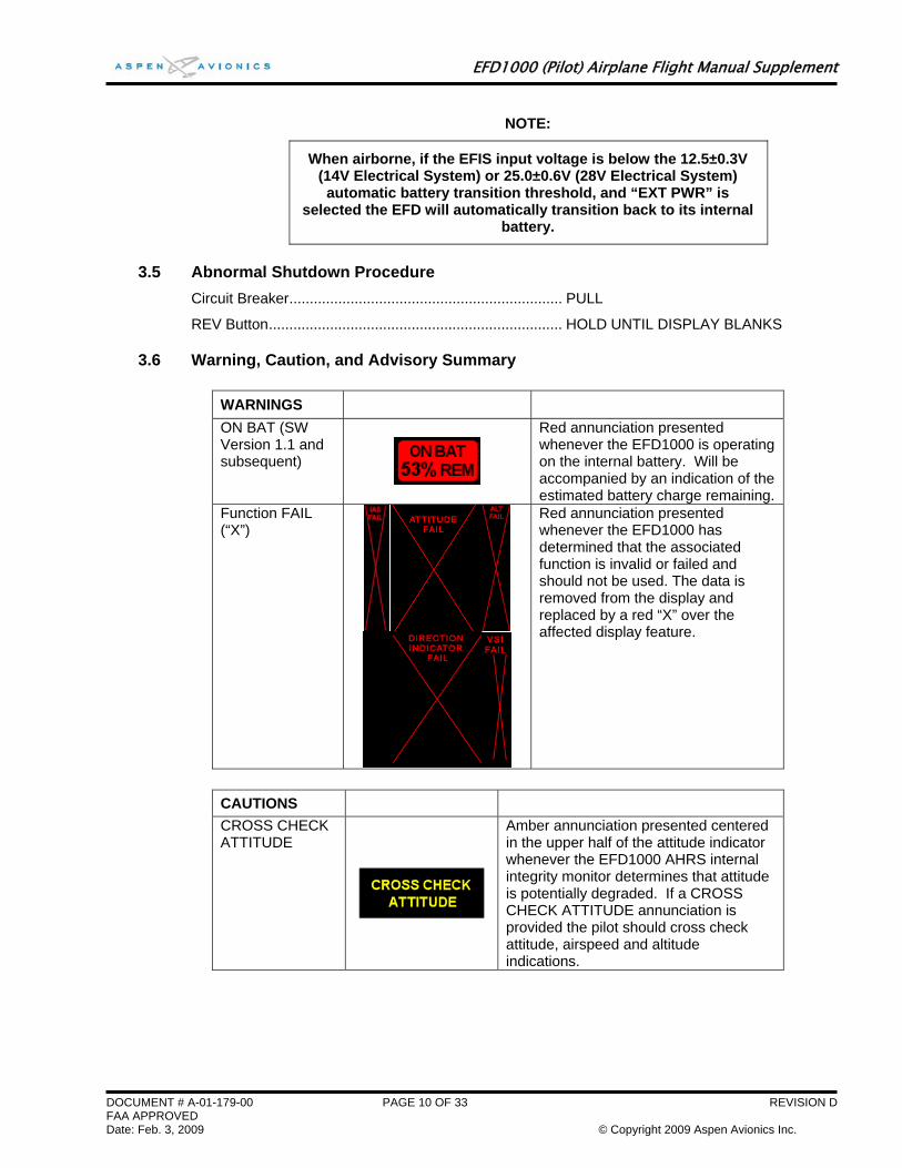
CAUTIONS CROSS CHECK ATTITUDE
Amber annunciation presented centered in the upper half of the attitude indicator whenever the EFD1000 AHRS internal integrity monitor determines that attitude is potentially degraded. If a CROSS CHECK ATTITUDE annunciation is provided the pilot should cross check attitude, airspeed and altitude indications.
DOCUMENT # A-01-179-00 PAGE 10 OF 33 REVISION D FAA APPROVED Date: Feb. 3, 2009 © Copyright 2009 Aspen Avionics Inc.
EFD1000 (Pilot) Airplane Flight Manual Supplement
DOCUMENT # A-01-179-00 PAGE 11 OF 33 REVISION D FAA APPROVED Date: Feb. 3, 2009 © Copyright 2009 Aspen Avionics Inc.
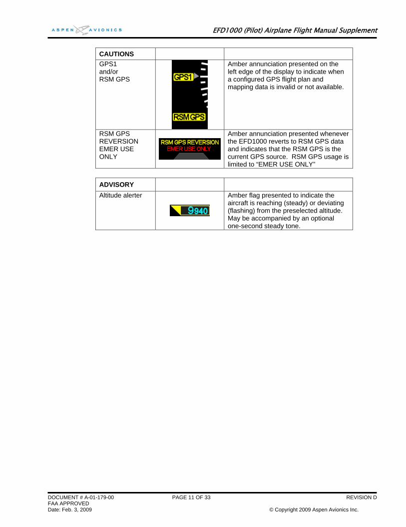
CAUTIONS GPS1 and/or RSM GPS
Amber annunciation presented on the left edge of the display to indicate when a configured GPS flight plan and mapping data is invalid or not available.
RSM GPS REVERSION EMER USE ONLY
Amber annunciation presented whenever the EFD1000 reverts to RSM GPS data and indicates that the RSM GPS is the current GPS source. RSM GPS usage is limited to “EMER USE ONLY”
ADVISORY Altitude alerter
Amber flag presented to indicate the aircraft is reaching (steady) or deviating (flashing) from the preselected altitude. May be accompanied by an optional one-second steady tone.
EFD1000 (Pilot) Airplane Flight Manual Supplement
DOCUMENT # A-01-179-00 PAGE 12 OF 33 REVISION D FAA APPROVED Date: Feb. 3, 2009 © Copyright 2009 Aspen Avionics Inc.
4 Normal Procedures
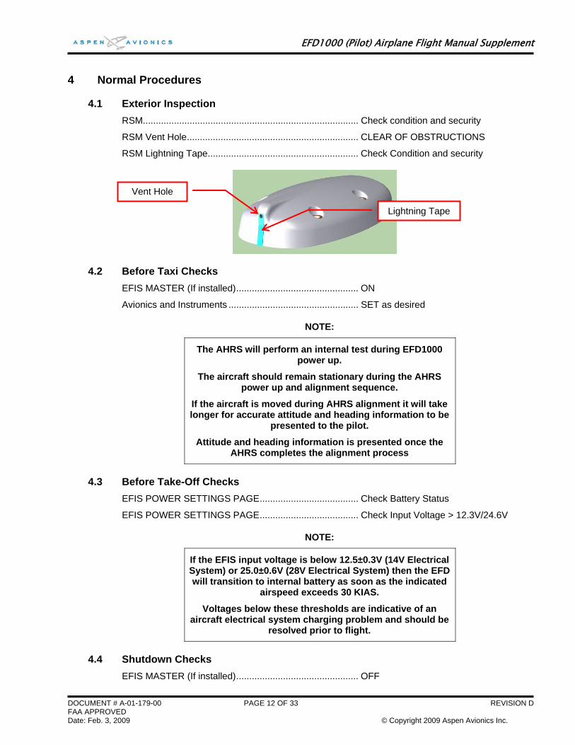
4.1 Exterior Inspection RSM................................................................................... Check condition and security
RSM Vent Hole.................................................................. CLEAR OF OBSTRUCTIONS
RSM Lightning Tape.......................................................... Check Condition and security
4.2 Before Taxi Checks EFIS MASTER (If installed)............................................... ON
Avionics and Instruments .................................................. SET as desired
NOTE:
The AHRS will perform an internal test during EFD1000 power up.
The aircraft should remain stationary during the AHRS power up and alignment sequence.
If the aircraft is moved during AHRS alignment it will take longer for accurate attitude and heading information to be
presented to the pilot.
Attitude and heading information is presented once the AHRS completes the alignment process
4.3 Before Take-Off Checks EFIS POWER SETTINGS PAGE...................................... Check Battery Status
EFIS POWER SETTINGS PAGE...................................... Check Input Voltage > 12.3V/24.6V
NOTE:
If the EFIS input voltage is below 12.5±0.3V (14V Electrical System) or 25.0±0.6V (28V Electrical System) then the EFD will transition to internal battery as soon as the indicated
airspeed exceeds 30 KIAS.
Voltages below these thresholds are indicative of an aircraft electrical system charging problem and should be
resolved prior to flight.
4.4 Shutdown Checks EFIS MASTER (If installed)............................................... OFF
Vent Hole
Lightning Tape

EFD1000 (Pilot) Airplane Flight Manual Supplement
5 Performance No change to basic Airplane Flight Manual or other performance information or placards.
DOCUMENT # A-01-179-00 PAGE 13 OF 33 REVISION D FAA APPROVED Date: Feb. 3, 2009 © Copyright 2009 Aspen Avionics Inc.
EFD1000 (Pilot) Airplane Flight Manual Supplement
6 System Description
6.1 General The EFD1000 “Pilot” system is a flat-panel LCD primary flight instrument that presents the pilot with displays of attitude, airspeed, altitude, vertical speed, slaved compass, slip/skid, and rate of turn information. The display head incorporates a solid-state Air Data and Attitude Heading Reference System (ADAHRS) to provide data for the flight instruments. The ADAHRS system uses data from its internal solid state rate gyros and accelerometers, pitot and static sensors, solid state magnetometer, and solid state temperature probes, all contained within the display head and RSM, to derive the aircraft attitude and air data solutions.
NOTE:
Although intuitive, a reasonable degree of familiarity is required to use the EFD1000.
6.2 Pilot Controls
6.2.1 Overview Pilot interaction with the EFD1000 is accomplished through two knobs with push/rotate function and 11 buttons located on the display bezel. Refer to Figure 2.
Two control knobs are used to control pilot settable bugs and references.
Three lower push buttons, located between the control knobs, are not used in the PILOT model.
Three dedicated buttons on the upper side of the right bezel control map range, display reversion, and provide access to the main menu.
Up to five soft keys on the lower half of the right bezel control frequently used commands. These five keys are also used when navigating the main menu.
6.2.2 Power Control To enhance safety, the EFD1000 includes an internal battery that allows the system to continue to operate in the event of a failure of the aircraft electrical system. This ensures that in addition to the standby instruments, the EFD1000 primary flight instrument continues to remain available for a period of time following the loss of all external supply power.
This internal battery is not required by regulation; however, it is good practice to verify that the status of the battery prior to takeoff.
The typical EFD1000 installation receives aircraft power from the battery bus via a dedicated circuit breaker and optionally, via an EFIS Master Switch.
Whenever indicated airspeed is invalid or below 30 KIAS the EFD1000 will power up and power down with the application or removal of external power. To turn on the system, turn on the aircraft Battery Master switch and, if installed, the optional EFIS Master switch. Reverse this process to turn the system off. A message is presented during the normal power down sequence to enable the pilot to abort the shutdown and switch to internal battery.
When IAS is greater than 30 KIAS and the input voltage is below 12.5±0.3V (14V Electrical System) or 25.0±0.6V (28V Electrical System) the EFD will automatically switch to its internal battery (e.g. aircraft charging system failure).
DOCUMENT # A-01-179-00 PAGE 14 OF 33 REVISION D FAA APPROVED Date: Feb. 3, 2009 © Copyright 2009 Aspen Avionics Inc.

EFD1000 (Pilot) Airplane Flight Manual Supplement
The EFD1000 internal battery will provide at least 30 minutes of power when it is fully charged. The battery provides power to the display head, RSM and emergency GPS. Reducing the backlight intensity will extend the battery operating time.
When operating from battery, battery charge status is indicated in the Main Menu “Power Settings” page. See section 6.5.
NOTE:
As a protection mechanism, the EFD1000 internal battery may not charge when the battery temperature is at extreme high or low temperatures. This situation may occur when the battery was
being used and system power is subsequently restored, or it may occur under high or low ambient temperatures.
If operation from the internal battery occurs during night and/or IFR operations, one should land as soon as possible, even if external power is restored, as the battery will not recharge
following restoration of external power until the battery temperature has returned to normal.
A unit operating from battery may be powered off using the “Shut Down” command available in the Power Settings Menu.
In the unlikely event that the normal power control is not working, the EFD may be forced to shut down by first pulling its associated circuit breaker and then pressing and holding the REV button for at least 5 seconds. (Refer to section 3.4 Abnormal Shutdown Procedure)
Battery charge status may be viewed from the “Power Settings” page of the Main Menu. See section 6.5 for more information.
DOCUMENT # A-01-179-00 PAGE 15 OF 33 REVISION D FAA APPROVED Date: Feb. 3, 2009 © Copyright 2009 Aspen Avionics Inc.
EFD1000 (Pilot) Airplane Flight Manual Supplement
DOCUMENT # A-01-179-00 PAGE 16 OF 33 REVISION D FAA APPROVED Date: Feb. 3, 2009 © Copyright 2009 Aspen Avionics Inc.
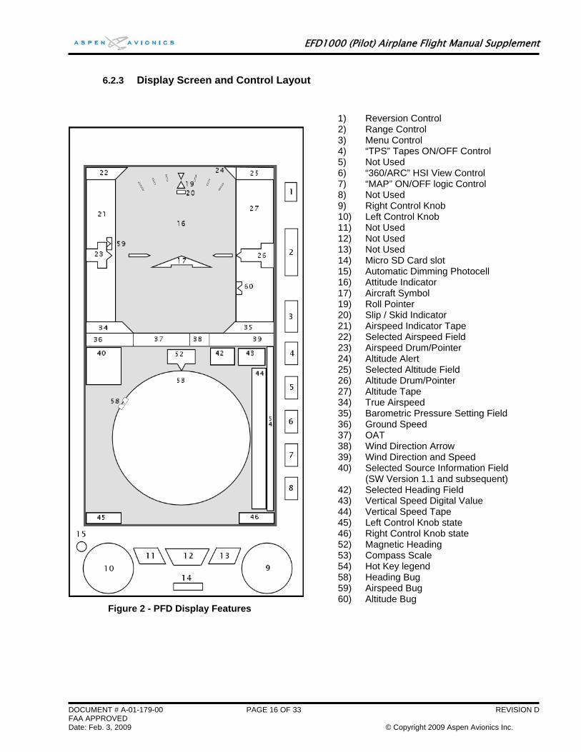
6.2.3 Display Screen and Control Layout
1) Reversion Control 2) Range Control
3) Menu Control 4) “TPS” Tapes ON/OFF Control 5) Not Used 6) “360/ARC” HSI View Control 7) “MAP” ON/OFF logic Control 8) Not Used 9) Right Control Knob 10) Left Control Knob 11) Not Used 12) Not Used 13) Not Used 14) Micro SD Card slot 15) Automatic Dimming Photocell 16) Attitude Indicator 17) Aircraft Symbol 19) Roll Pointer 20) Slip / Skid Indicator 21) Airspeed Indicator Tape 22) Selected Airspeed Field 23) Airspeed Drum/Pointer 24) Altitude Alert 25) Selected Altitude Field 26) Altitude Drum/Pointer 27) Altitude Tape 34) True Airspeed 35) Barometric Pressure Setting Field 36) Ground Speed 37) OAT 38) Wind Direction Arrow 39) Wind Direction and Speed 40) Selected Source Information Field
(SW Version 1.1 and subsequent) 42) Selected Heading Field 43) Vertical Speed Digital Value 44) Vertical Speed Tape 45) Left Control Knob state 46) Right Control Knob state 52) Magnetic Heading 53) Compass Scale 54) Hot Key legend 58) Heading Bug 59) Airspeed Bug 60) Altitude Bug
Figure 2 - PFD Display Features
EFD1000 (Pilot) Airplane Flight Manual Supplement
6.2.4 Control Knobs General
Two control knobs on the EFD bezel are used to adjust pilot editable data fields. The left knob adjusts data fields on the left side of the display, and the right knob adjusts data fields on the right side of the display.
The knob logic includes active and inactive states to prevent inadvertent adjustment of editable fields. After 10 seconds of inactivity, the knob returns to an inactive state and also returns to the “home” state defined for that knob. A single push activates an inactive knob. Pushing the knob again will advance the knob to the next editable field (if applicable) in a round-robin sequence.
When inactive, the knob legend is rendered in Cyan. Once activated, the knob legend and associated data field and bug (where appropriate) are rendered in magenta.
Left control knob
The left control knob adjusts the Indicated Airspeed Bug “IAS” editable fields. To adjust this values PUSH the knob to activate it, verify “IAS”: is displayed in magenta, then ROTATE the knob to set the value (clockwise to increase, counterclockwise to decrease).
Right control knob
The right control knob controls Heading Bug “HDG”, Altitude Bug “ALT”, and Barometric Pressure Setting “BARO” editable fields in that order. To adjust these values PUSH the knob in a round robin fashion until the desired field text turns magenta, then ROTATE the knob to set the value (clockwise to increase, counterclockwise to decrease).
The home state for the right knob is “HDG.”
6.2.5 Setting Flight Instruments The following procedures are used to adjust pilot-editable data on the EFD1000:
Heading Bug Set
To set the heading bug, repeatedly PUSH the right control knob until the HDG field is enabled for editing. ROTATE the knob to the desired setting.
Altitude Bug Set
To set the altitude bug, repeatedly PUSH the right control knob until the ALT field is enabled for editing. ROTATE the knob to the desired setting
Barometric Pressure Set
To set the barometric pressure, repeatedly PUSH the right control knob until the BARO field is enabled for editing. ROTATE the knob to the desired setting.
NOTE:
The barometric pressure setting on the standby altimeter must be set whenever the value is adjusted on the EFD1000.
Indicated Airspeed Bug Set
To set the indicated airspeed bug, repeatedly PUSH the left control knob until the IAS field is enabled for editing. ROTATE the knob to the desired setting.
DOCUMENT # A-01-179-00 PAGE 17 OF 33 REVISION D FAA APPROVED Date: Feb. 3, 2009 © Copyright 2009 Aspen Avionics Inc.
EFD1000 (Pilot) Airplane Flight Manual Supplement
6.2.6 Knob Sync Function Editable fields may be synchronized as a function of data type as described in Table 1 below. Whenever a control knob is held for approximately one second the active data type will be “sync’d” as follows:
Left Knob Data Type
SYNC Behavior Right Knob Data Type
SYNC Behavior
IAS The airspeed bug is set to the current IAS.
HDG The heading bug is set to the current heading.
ALT The altimeter bug is set to the current altitude.
BARO The barometric pressure is set to standard pressure of 29.92 in Hg or 1013 mB.
Table 1 - Knob "Sync" Operation
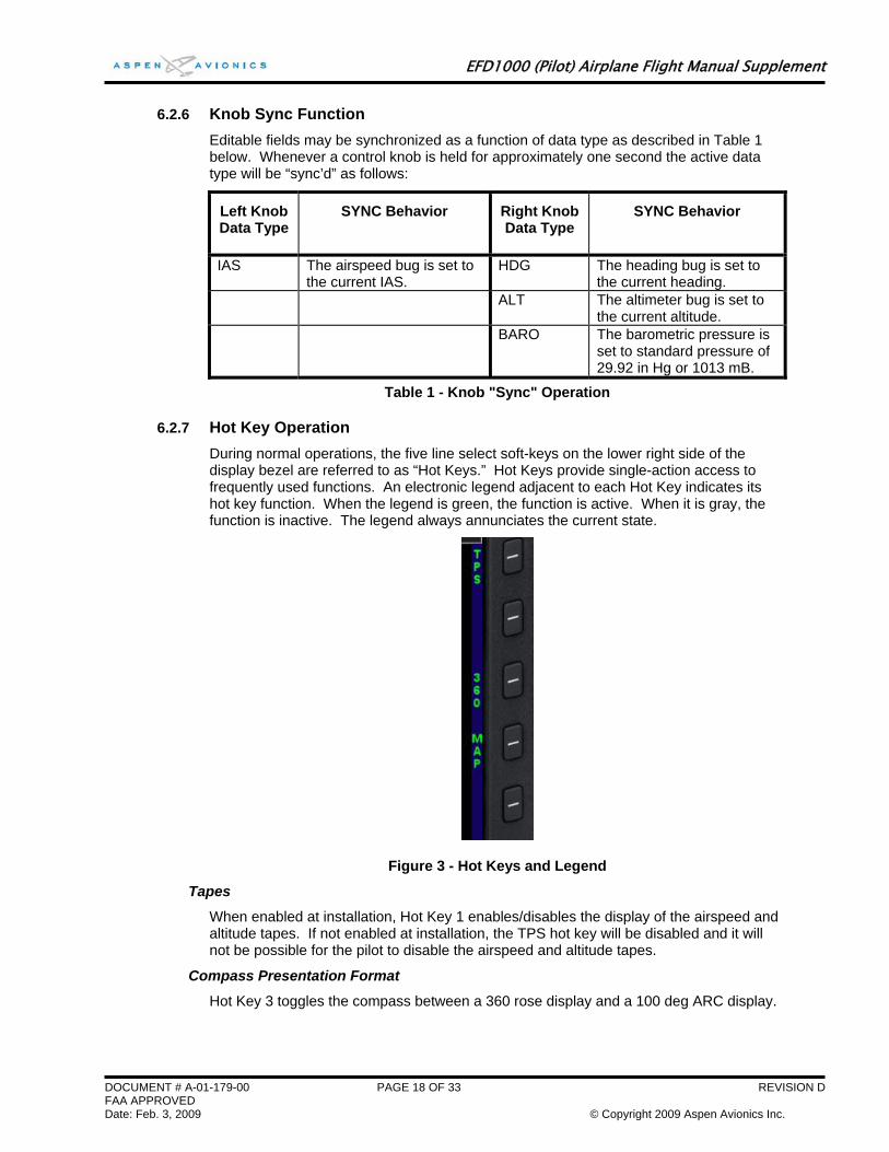
6.2.7 Hot Key Operation During normal operations, the five line select soft-keys on the lower right side of the display bezel are referred to as “Hot Keys.” Hot Keys provide single-action access to frequently used functions. An electronic legend adjacent to each Hot Key indicates its hot key function. When the legend is green, the function is active. When it is gray, the function is inactive. The legend always annunciates the current state.
Figure 3 - Hot Keys and Legend
Tapes
When enabled at installation, Hot Key 1 enables/disables the display of the airspeed and altitude tapes. If not enabled at installation, the TPS hot key will be disabled and it will not be possible for the pilot to disable the airspeed and altitude tapes.
Compass Presentation Format
Hot Key 3 toggles the compass between a 360 rose display and a 100 deg ARC display.
DOCUMENT # A-01-179-00 PAGE 18 OF 33 REVISION D FAA APPROVED Date: Feb. 3, 2009 © Copyright 2009 Aspen Avionics Inc.
EFD1000 (Pilot) Airplane Flight Manual Supplement
Basemap and Declutter Level
SW Version 1.0:
Hot Key 4 is used to enable and disable the GPS basemap. Refer to Section 6.4 for additional information about the basemap.
Each successive push of the MAP hot key will turn the basemap on and off. In the Pilot model of the EFD1000, basemap consists of data associated with the active GPS flight plan
The FP ONLY selection displays just the flight plan legs and waypoints associated with the GPS flight plan, and no other basemap features.
OFF removes all basemap and flight plan symbology.
Separate basemap settings are retained for the 360 and ARC compass modes.
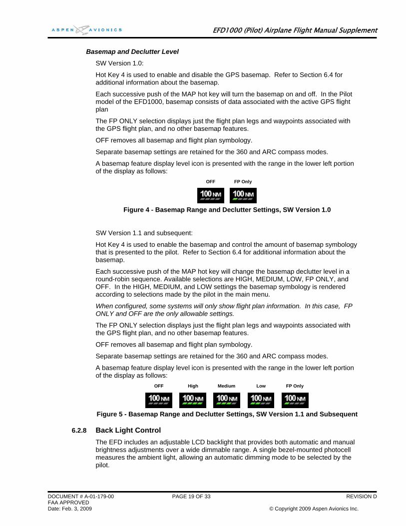
A basemap feature display level icon is presented with the range in the lower left portion of the display as follows:
OFF FP Only
Figure 4 - Basemap Range and Declutter Settings, SW Version 1.0
SW Version 1.1 and subsequent:
Hot Key 4 is used to enable the basemap and control the amount of basemap symbology that is presented to the pilot. Refer to Section 6.4 for additional information about the basemap.
Each successive push of the MAP hot key will change the basemap declutter level in a round-robin sequence. Available selections are HIGH, MEDIUM, LOW, FP ONLY, and OFF. In the HIGH, MEDIUM, and LOW settings the basemap symbology is rendered according to selections made by the pilot in the main menu.
When configured, some systems will only show flight plan information. In this case, FP ONLY and OFF are the only allowable settings.
The FP ONLY selection displays just the flight plan legs and waypoints associated with the GPS flight plan, and no other basemap features.
OFF removes all basemap and flight plan symbology.
Separate basemap settings are retained for the 360 and ARC compass modes.
A basemap feature display level icon is presented with the range in the lower left portion of the display as follows:
OFF High Medium Low FP Only
Figure 5 - Basemap Range and Declutter Settings, SW Version 1.1 and Subsequent
6.2.8 Back Light Control The EFD includes an adjustable LCD backlight that provides both automatic and manual brightness adjustments over a wide dimmable range. A single bezel-mounted photocell measures the ambient light, allowing an automatic dimming mode to be selected by the pilot.
DOCUMENT # A-01-179-00 PAGE 19 OF 33 REVISION D FAA APPROVED Date: Feb. 3, 2009 © Copyright 2009 Aspen Avionics Inc.
EFD1000 (Pilot) Airplane Flight Manual Supplement
Manual dimming control is enabled by the pilot to override the photocell input and adjust the display to any desired intensity level (except off).
In either mode, the bezel-key backlighting is maintained at a fixed brightness level.
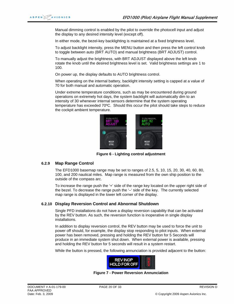
To adjust backlight intensity, press the MENU button and then press the left control knob to toggle between auto (BRT AUTO) and manual brightness (BRT ADJUST) control.
To manually adjust the brightness, with BRT ADJUST displayed above the left knob rotate the knob until the desired brightness level is set. Valid brightness settings are 1 to 100.
On power up, the display defaults to AUTO brightness control.
When operating on the internal battery, backlight intensity setting is capped at a value of 70 for both manual and automatic operation.
Under extreme temperature conditions, such as may be encountered during ground operations on extremely hot days, the system backlight will automatically dim to an intensity of 30 whenever internal sensors determine that the system operating temperature has exceeded 70ºC. Should this occur the pilot should take steps to reduce the cockpit ambient temperature.
Figure 6 - Lighting control adjustment
6.2.9 Map Range Control The EFD1000 basemap range may be set to ranges of 2.5, 5, 10, 15, 20, 30, 40, 60, 80, 100, and 200 nautical miles. Map range is measured from the own ship position to the outside of the compass arc.
To increase the range push the ‘+’ side of the range key located on the upper right side of the bezel. To decrease the range push the ‘–‘ side of the key. The currently selected map range is displayed in the lower left corner of the display.
6.2.10 Display Reversion Control and Abnormal Shutdown Single PFD installations do not have a display reversion capability that can be activated by the REV button. As such, the reversion function is inoperative in single display installations.
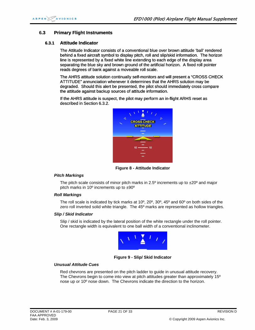
In addition to display reversion control, the REV button may be used to force the unit to power off should, for example, the display stop responding to pilot inputs. When external power has been removed, pressing and holding the REV button for 5 Seconds will produce in an immediate system shut down. When external power is available, pressing and holding the REV button for 5 seconds will result in a system restart.
While the button is pressed, the following annunciation is provided adjacent to the button:
Figure 7 - Power Reversion Annunciation
DOCUMENT # A-01-179-00 PAGE 20 OF 33 REVISION D FAA APPROVED Date: Feb. 3, 2009 © Copyright 2009 Aspen Avionics Inc.
EFD1000 (Pilot) Airplane Flight Manual Supplement
DOCUMENT # A-01-179-00 PAGE 21 OF 33 REVISION D FAA APPROVED Date: Feb. 3, 2009 © Copyright 2009 Aspen Avionics Inc.
6.3 Primary Flight Instruments .3 Primary Flight Instruments
6.3.1 Attitude Indicator 6.3.1 Attitude Indicator The Attitude Indicator consists of a conventional blue over brown attitude ‘ball’ rendered behind a fixed aircraft symbol to display pitch, roll and slip/skid information. The horizon line is represented by a fixed white line extending to each edge of the display area separating the blue sky and brown ground of the artificial horizon. A fixed roll pointer reads degrees of bank against a moveable roll scale.
The Attitude Indicator consists of a conventional blue over brown attitude ‘ball’ rendered behind a fixed aircraft symbol to display pitch, roll and slip/skid information. The horizon line is represented by a fixed white line extending to each edge of the display area separating the blue sky and brown ground of the artificial horizon. A fixed roll pointer reads degrees of bank against a moveable roll scale.
The AHRS attitude solution continually self-monitors and will present a “CROSS CHECK ATTITUDE” annunciation whenever it determines that the AHRS solution may be degraded. Should this alert be presented, the pilot should immediately cross compare the attitude against backup sources of attitude information.
The AHRS attitude solution continually self-monitors and will present a “CROSS CHECK ATTITUDE” annunciation whenever it determines that the AHRS solution may be degraded. Should this alert be presented, the pilot should immediately cross compare the attitude against backup sources of attitude information.
If the AHRS attitude is suspect, the pilot may perform an in-flight ARHS reset as described in Section 6.3.2. If the AHRS attitude is suspect, the pilot may perform an in-flight ARHS reset as described in Section 6.3.2.
Figure 8 - Attitude Indicator
Pitch Markings
The pitch scale consists of minor pitch marks in 2.5º increments up to ±20º and major pitch marks in 10º increments up to ±90º
Roll Markings
The roll scale is indicated by tick marks at 10º, 20º, 30º, 45º and 60º on both sides of the zero roll inverted solid white triangle. The 45º marks are represented as hollow triangles.
Slip / Skid Indicator
Slip / skid is indicated by the lateral position of the white rectangle under the roll pointer. One rectangle width is equivalent to one ball width of a conventional inclinometer.
Figure 9 - Slip/ Skid Indicator
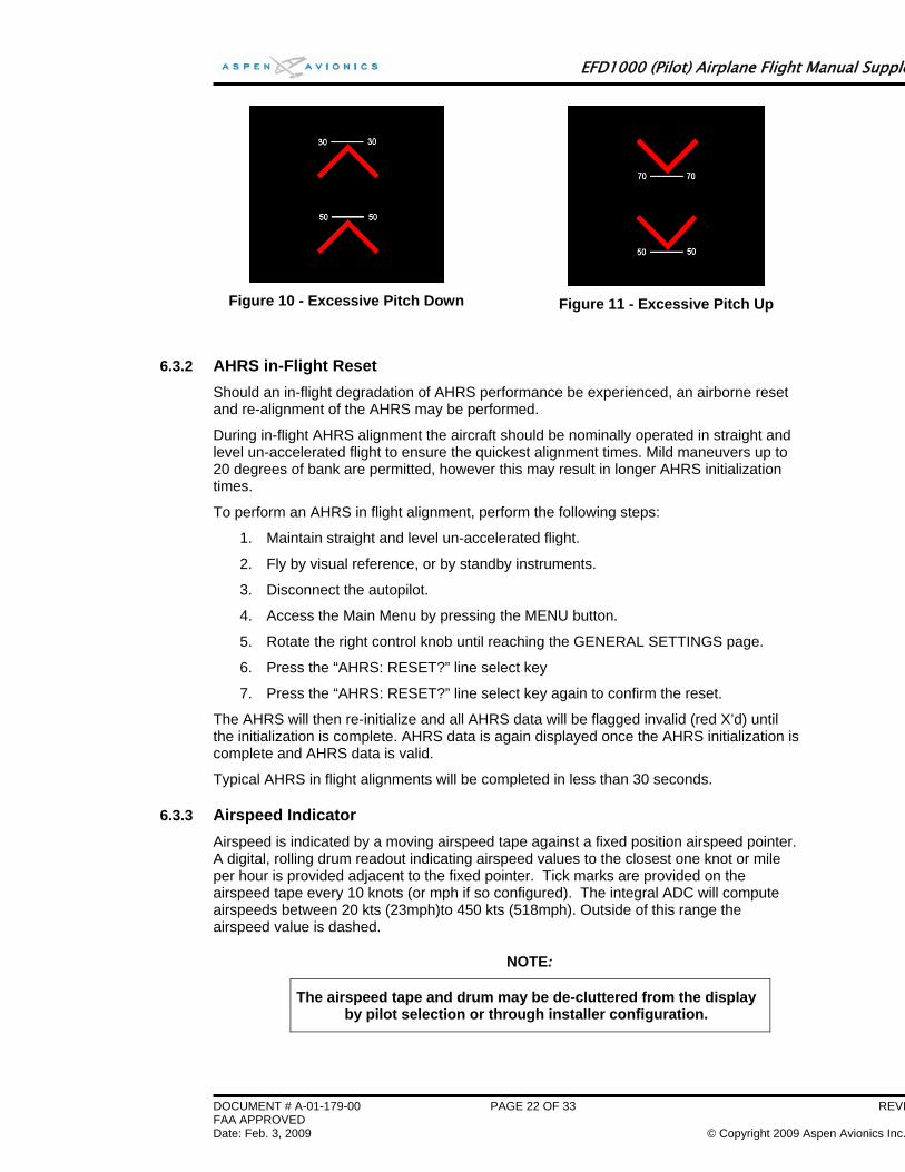
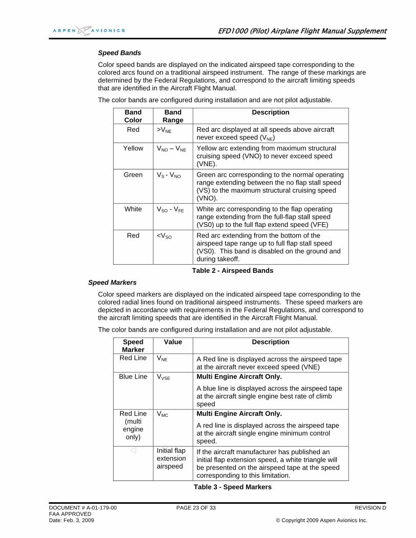
Unusual Attitude Cues
Red chevrons are presented on the pitch ladder to guide in unusual attitude recovery. The Chevrons begin to come into view at pitch attitudes greater than approximately 15º nose up or 10º nose down. The Chevrons indicate the direction to the horizon.
EFD1000 (Pilot) Airplane Flight Manual Supple
Figure 10 - Excessive Pitch Down
Figure 11 - Excessive Pitch Up
6.3.2 AHRS in-Flight Reset Should an in-flight degradation of AHRS performance be experienced, an airborne reset and re-alignment of the AHRS may be performed.
During in-flight AHRS alignment the aircraft should be nominally operated in straight and level un-accelerated flight to ensure the quickest alignment times. Mild maneuvers up to 20 degrees of bank are permitted, however this may result in longer AHRS initialization times.
To perform an AHRS in flight alignment, perform the following steps:
1. Maintain straight and level un-accelerated flight.
2. Fly by visual reference, or by standby instruments.
3. Disconnect the autopilot.
4. Access the Main Menu by pressing the MENU button.
5. Rotate the right control knob until reaching the GENERAL SETTINGS page.
6. Press the “AHRS: RESET?” line select key
7. Press the “AHRS: RESET?” line select key again to confirm the reset.
The AHRS will then re-initialize and all AHRS data will be flagged invalid (red X’d) until the initialization is complete. AHRS data is again displayed once the AHRS initialization is complete and AHRS data is valid.
Typical AHRS in flight alignments will be completed in less than 30 seconds.
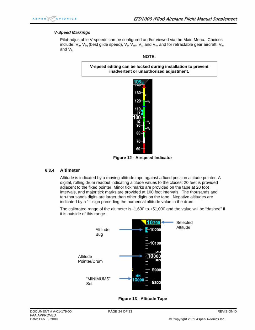
6.3.3 Airspeed Indicator Airspeed is indicated by a moving airspeed tape against a fixed position airspeed pointer. A digital, rolling drum readout indicating airspeed values to the closest one knot or mile per hour is provided adjacent to the fixed pointer. Tick marks are provided on the airspeed tape every 10 knots (or mph if so configured). The integral ADC will compute airspeeds between 20 kts (23mph)to 450 kts (518mph). Outside of this range the airspeed value is dashed.
NOTE:
The airspeed tape and drum may be de-cluttered from the display by pilot selection or through installer configuration.
DOCUMENT # A-01-179-00 PAGE 22 OF 33 REVIFAA APPROVED Date: Feb. 3, 2009 © Copyright 2009 Aspen Avionics Inc.
EFD1000 (Pilot) Airplane Flight Manual Supplement
DOCUMENT # A-01-179-00 PAGE 23 OF 33 REVISION D FAA APPROVED Date: Feb. 3, 2009 © Copyright 2009 Aspen Avionics Inc.
Speed Bands
Color speed bands are displayed on the indicated airspeed tape corresponding to the colored arcs found on a traditional airspeed instrument. The range of these markings are determined by the Federal Regulations, and correspond to the aircraft limiting speeds that are identified in the Aircraft Flight Manual.
The color bands are configured during installation and are not pilot adjustable.
Band Color
Band Range
Description
Red >VNE Red arc displayed at all speeds above aircraft never exceed speed (VNE)
Yellow VNO – VNE Yellow arc extending from maximum structural cruising speed (VNO) to never exceed speed (VNE).
Green VS - VNO Green arc corresponding to the normal operating range extending between the no flap stall speed (VS) to the maximum structural cruising speed (VNO).
White VSO - VFE White arc corresponding to the flap operating range extending from the full-flap stall speed (VS0) up to the full flap extend speed (VFE)
Red <VSO Red arc extending from the bottom of the airspeed tape range up to full flap stall speed (VS0). This band is disabled on the ground and during takeoff.
Table 2 - Airspeed Bands
Speed Markers
Color speed markers are displayed on the indicated airspeed tape corresponding to the colored radial lines found on traditional airspeed instruments. These speed markers are depicted in accordance with requirements in the Federal Regulations, and correspond to the aircraft limiting speeds that are identified in the Aircraft Flight Manual.
The color bands are configured during installation and are not pilot adjustable.
Speed Marker
Value Description
Red Line VNE A Red line is displayed across the airspeed tape at the aircraft never exceed speed (VNE)
Blue Line VVSE Multi Engine Aircraft Only.
A blue line is displayed across the airspeed tape at the aircraft single engine best rate of climb speed
Red Line (multi engine only)
VMC Multi Engine Aircraft Only.
A red line is displayed across the airspeed tape at the aircraft single engine minimum control speed.
Initial flap extension airspeed
If the aircraft manufacturer has published an initial flap extension speed, a white triangle will be presented on the airspeed tape at the speed corresponding to this limitation.
Table 3 - Speed Markers
EFD1000 (Pilot) Airplane Flight Manual Supplement
V-Speed Markings
Pilot-adjustable V-speeds can be configured and/or viewed via the Main Menu. Choices include: Va, Vbg (best glide speed), Vr, Vref, Vx, and Vy, and for retractable gear aircraft: Vle and Vlo
NOTE:
V-speed editing can be locked during installation to prevent inadvertent or unauthorized adjustment.
Figure 12 - Airspeed Indicator
6.3.4 Altimeter Altitude is indicated by a moving altitude tape against a fixed position altitude pointer. A digital, rolling drum readout indicating altitude values to the closest 20 feet is provided adjacent to the fixed pointer. Minor tick marks are provided on the tape at 20 foot intervals, and major tick marks are provided at 100 foot intervals. The thousands and ten-thousands digits are larger than other digits on the tape. Negative altitudes are indicated by a “-“ sign preceding the numerical altitude value in the drum.
The calibrated range of the altimeter is -1,600 to +51,000 and the value will be “dashed” if it is outside of this range.
Altitude Pointer/Drum
Altitude Bug
“MINIMUMS” Set
Selected Altitude
Figure 13 - Altitude Tape
DOCUMENT # A-01-179-00 PAGE 24 OF 33 REVISION D FAA APPROVED Date: Feb. 3, 2009 © Copyright 2009 Aspen Avionics Inc.
EFD1000 (Pilot) Airplane Flight Manual Supplement
DOCUMENT # A-01-179-00 PAGE 25 OF 33 REVISION D FAA APPROVED Date: Feb. 3, 2009 © Copyright 2009 Aspen Avionics Inc.
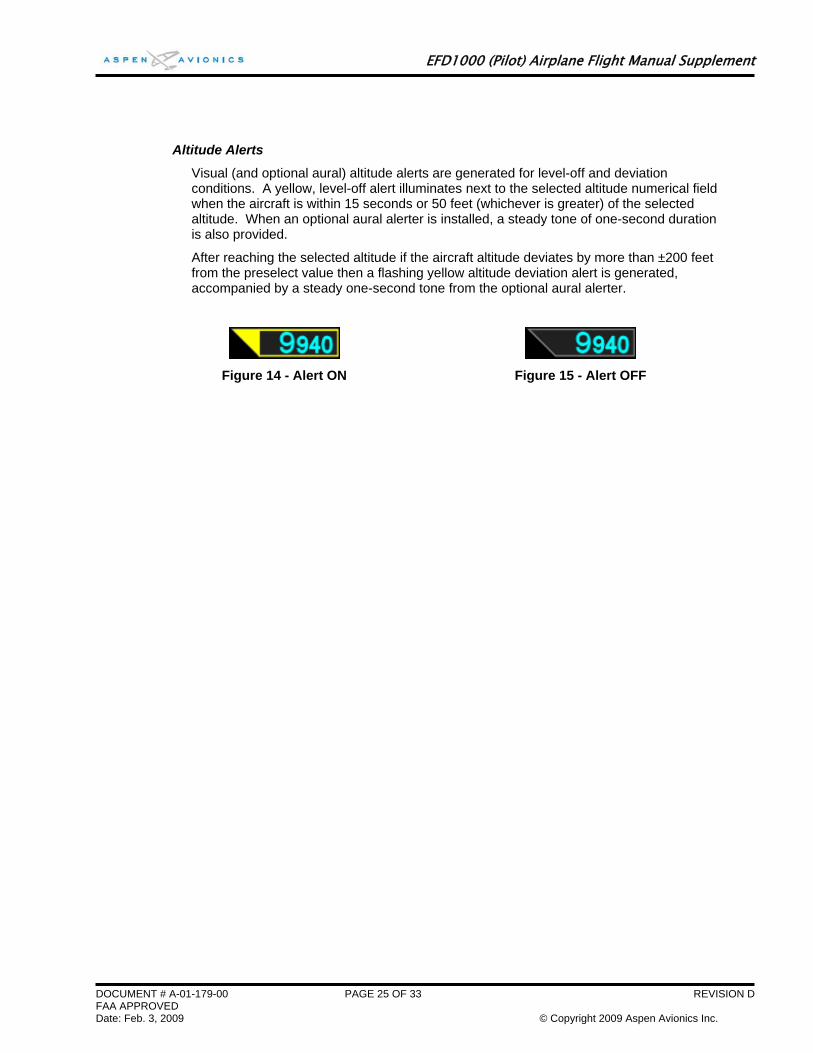
Altitude Alerts
Visual (and optional aural) altitude alerts are generated for level-off and deviation conditions. A yellow, level-off alert illuminates next to the selected altitude numerical field when the aircraft is within 15 seconds or 50 feet (whichever is greater) of the selected altitude. When an optional aural alerter is installed, a steady tone of one-second duration is also provided.
After reaching the selected altitude if the aircraft altitude deviates by more than ±200 feet from the preselect value then a flashing yellow altitude deviation alert is generated, accompanied by a steady one-second tone from the optional aural alerter.
Figure 15 - Alert OFF Figure 14 - Alert ON
EFD1000 (Pilot) Airplane Flight Manual Supplement
DOCUMENT # A-01-179-00 PAGE 26 OF 33 REVISION D FAA APPROVED Date: Feb. 3, 2009 © Copyright 2009 Aspen Avionics Inc.
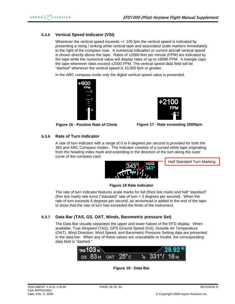
6.3.5 Vertical Speed Indicator (VSI) Whenever the vertical speed exceeds +/- 100 fpm the vertical speed is indicated by presenting a rising / sinking white vertical tape and associated scale markers immediately to the right of the compass rose. A numerical indication or current aircraft vertical speed is shown directly above the tape. Rates of ±2000 feet per minute (FPM) are indicated by the tape while the numerical value will display rates of up to ±9990 FPM. A triangle caps the tape whenever rates exceed ±2000 FPM. The vertical speed data field will be “dashed” whenever the vertical speed is 10,000 fpm or greater.
In the ARC compass mode only the digital vertical speed value is presented.
Figure 16 - Positive Rate of Climb
Figure 17 - Rate exceeding 2000fpm
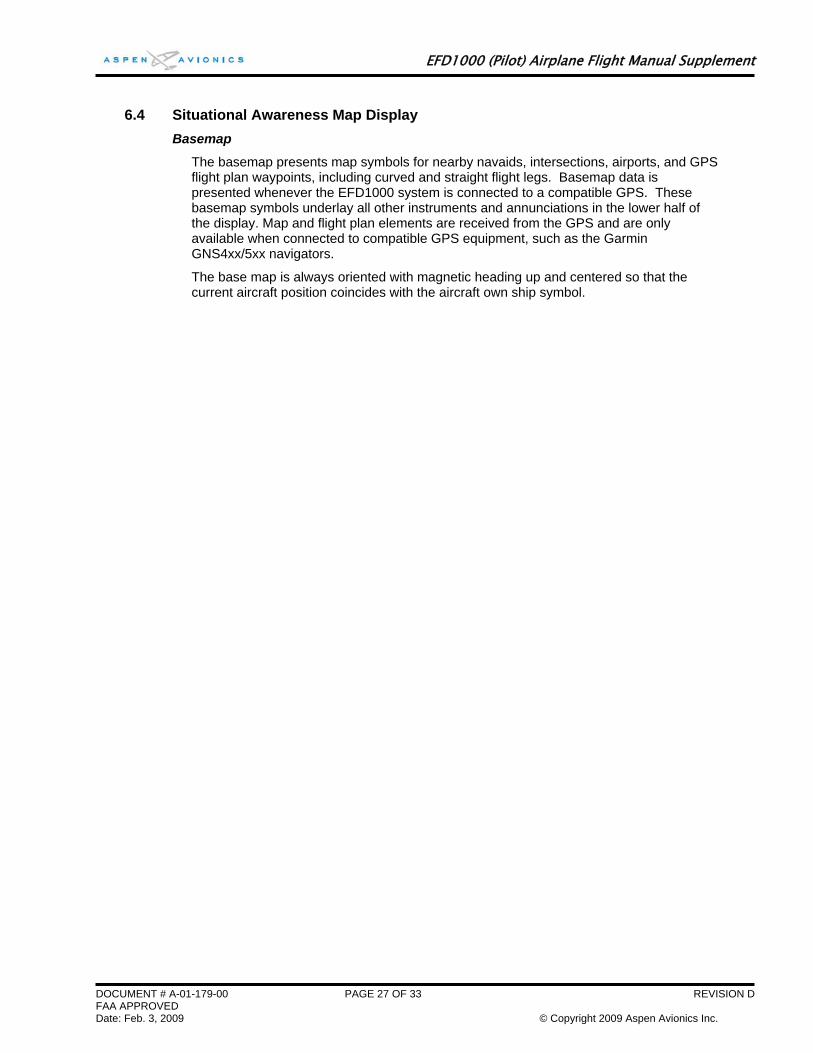
6.3.6 Rate of Turn Indicator A rate of turn indicator with a range of 0 to 6 degrees per second is provided for both the 360 and ARC Compass modes. The indicator consists of a curved white tape originating from the heading index mark and extending in the direction of the turn along the outer curve of the compass card.
Figure 18 Rate Indicator
The rate of turn indicator features scale marks for full (thick tick mark) and half “standard” (thin tick mark) rate turns (“standard” rate of turn = 3 degrees per second). When the rate of turn exceeds 6 degrees per second, an arrowhead is added to the end of the tape to show that the rate of turn has exceeded the limits of the instrument.
6.3.7 Data Bar (TAS, GS, OAT, Winds, Barometric pressure Set) The Data Bar visually separates the upper and lower halves of the EFD display. When available, True Airspeed (TAS), GPS Ground Speed (GS), Outside Air Temperature (OAT), Wind Direction, Wind Speed, and Barometric Pressure Setting data are presented in the data bar. When any of these values are unavailable or invalid, the corresponding data field is “dashed.”
Figure 19 - Data Bar
Half Standard Turn Marking
EFD1000 (Pilot) Airplane Flight Manual Supplement
6.4 Situational Awareness Map Display Basemap
The basemap presents map symbols for nearby navaids, intersections, airports, and GPS flight plan waypoints, including curved and straight flight legs. Basemap data is presented whenever the EFD1000 system is connected to a compatible GPS. These basemap symbols underlay all other instruments and annunciations in the lower half of the display. Map and flight plan elements are received from the GPS and are only available when connected to compatible GPS equipment, such as the Garmin GNS4xx/5xx navigators.
The base map is always oriented with magnetic heading up and centered so that the current aircraft position coincides with the aircraft own ship symbol.
DOCUMENT # A-01-179-00 PAGE 27 OF 33 REVISION D FAA APPROVED Date: Feb. 3, 2009 © Copyright 2009 Aspen Avionics Inc.
EFD1000 (Pilot) Airplane Flight Manual Supplement
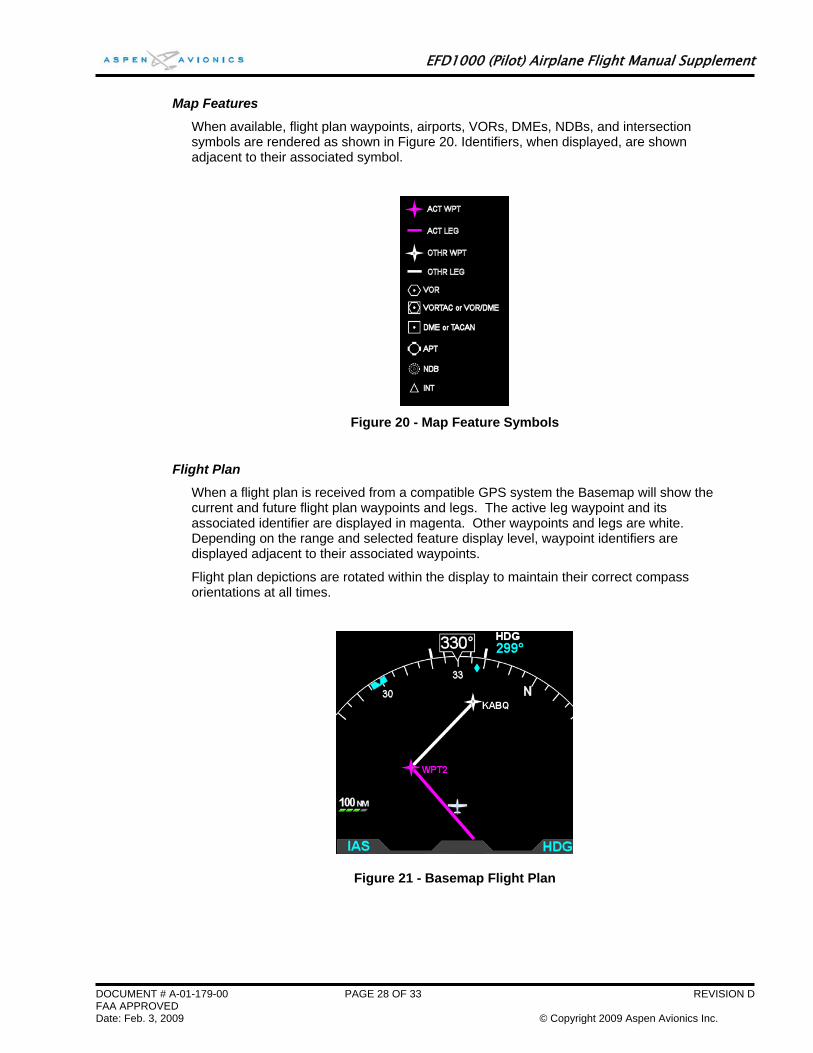
Map Features
When available, flight plan waypoints, airports, VORs, DMEs, NDBs, and intersection symbols are rendered as shown in Figure 20. Identifiers, when displayed, are shown adjacent to their associated symbol.
Figure 20 - Map Feature Symbols
Flight Plan
When a flight plan is received from a compatible GPS system the Basemap will show the current and future flight plan waypoints and legs. The active leg waypoint and its associated identifier are displayed in magenta. Other waypoints and legs are white. Depending on the range and selected feature display level, waypoint identifiers are displayed adjacent to their associated waypoints.
Flight plan depictions are rotated within the display to maintain their correct compass orientations at all times.
Figure 21 - Basemap Flight Plan
DOCUMENT # A-01-179-00 PAGE 28 OF 33 REVISION D FAA APPROVED Date: Feb. 3, 2009 © Copyright 2009 Aspen Avionics Inc.
EFD1000 (Pilot) Airplane Flight Manual Supplement
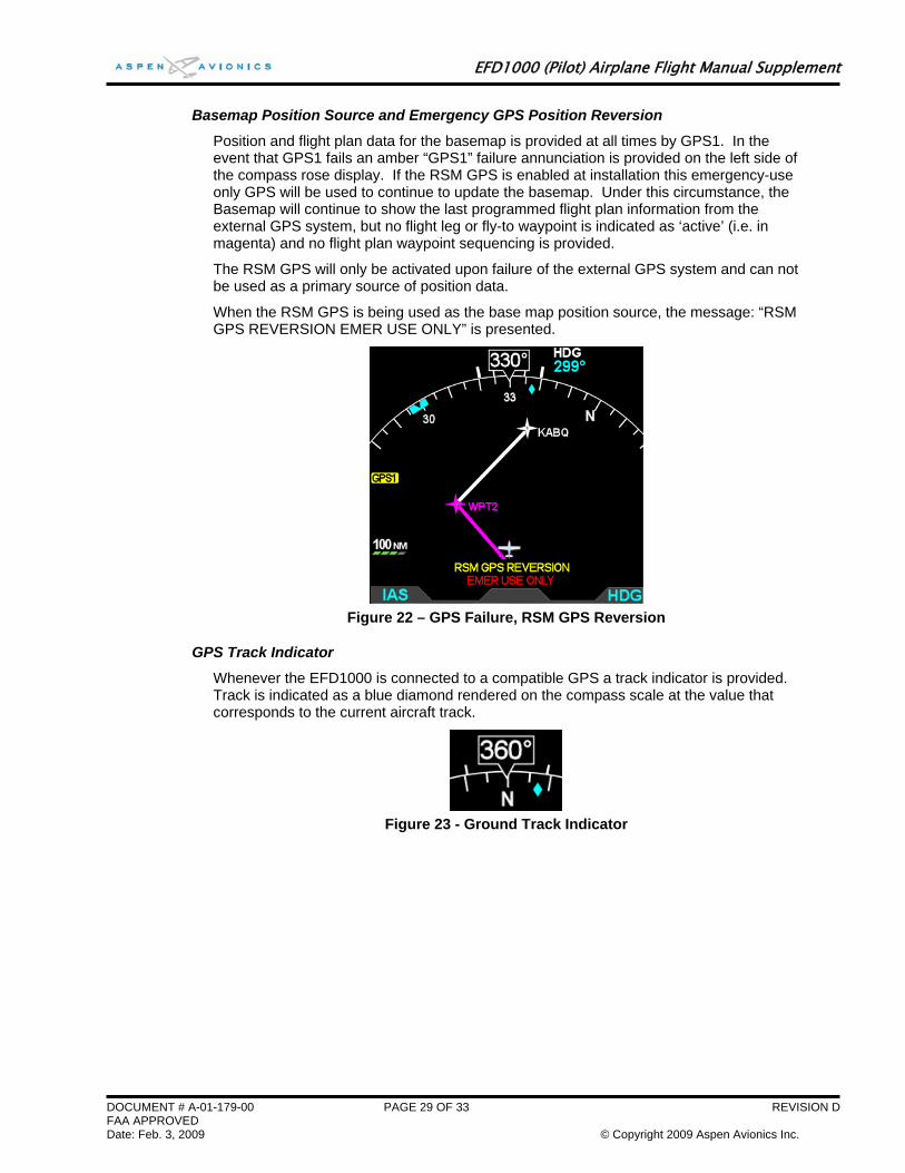
Basemap Position Source and Emergency GPS Position Reversion
Position and flight plan data for the basemap is provided at all times by GPS1. In the event that GPS1 fails an amber “GPS1” failure annunciation is provided on the left side of the compass rose display. If the RSM GPS is enabled at installation this emergency-use only GPS will be used to continue to update the basemap. Under this circumstance, the Basemap will continue to show the last programmed flight plan information from the external GPS system, but no flight leg or fly-to waypoint is indicated as ‘active’ (i.e. in magenta) and no flight plan waypoint sequencing is provided.
The RSM GPS will only be activated upon failure of the external GPS system and can not be used as a primary source of position data.
When the RSM GPS is being used as the base map position source, the message: “RSM GPS REVERSION EMER USE ONLY” is presented.
Figure 22 – GPS Failure, RSM GPS Reversion
GPS Track Indicator
Whenever the EFD1000 is connected to a compatible GPS a track indicator is provided. Track is indicated as a blue diamond rendered on the compass scale at the value that corresponds to the current aircraft track.
Figure 23 - Ground Track Indicator
DOCUMENT # A-01-179-00 PAGE 29 OF 33 REVISION D FAA APPROVED Date: Feb. 3, 2009 © Copyright 2009 Aspen Avionics Inc.
EFD1000 (Pilot) Airplane Flight Manual Supplement
6.5 Main Menu Operation .5 Main Menu Operation
6.5.1 Menu Controls 6.5.1 Menu Controls The EFD1000 Main menu is used to adjust various system configuration settings and preferences. To select the Main Menu, press the MENU button on the right side of the display bezel. To leave the menu, press the MENU button again. Menu items are shown exclusively in the lower half of the EFD1000 display in the region below the data bar.
The EFD1000 Main menu is used to adjust various system configuration settings and preferences. To select the Main Menu, press the MENU button on the right side of the display bezel. To leave the menu, press the MENU button again. Menu items are shown exclusively in the lower half of the EFD1000 display in the region below the data bar.
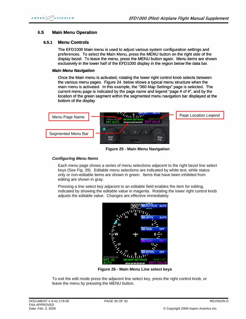
Main Menu Navigation Main Menu Navigation
Once the Main menu is activated, rotating the lower right control knob selects between the various menu pages. Figure 24 below shows a typical menu structure when the main menu is activated. In this example, the “360 Map Settings” page is selected. The current menu page is indicated by the page name and legend “page # of #”, and by the location of the green segment within the segmented menu navigation bar displayed at the bottom of the display
Once the Main menu is activated, rotating the lower right control knob selects between the various menu pages. Figure 24 below shows a typical menu structure when the main menu is activated. In this example, the “360 Map Settings” page is selected. The current menu page is indicated by the page name and legend “page # of #”, and by the location of the green segment within the segmented menu navigation bar displayed at the bottom of the display
Figure 25 - Main Menu Navigation
Configuring Menu Items
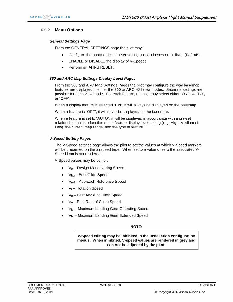
Each menu page shows a series of menu selections adjacent to the right bezel line select keys (See Fig. 39). Editable menu selections are indicated by white text, while status only or non-editable items are shown in green. Items that have been inhibited from editing are shown in gray.
Pressing a line select key adjacent to an editable field enables the item for editing, indicated by showing the editable value in magenta. Rotating the lower right control knob adjusts the editable value. Changes are effective immediately.
Figure 26 - Main Menu Line select keys
To exit the edit mode press the adjacent line select key, press the right control knob, or leave the menu by pressing the MENU button.
Menu Page Name Page Location Legend
Segmented Menu Bar
DOCUMENT # A-01-179-00 PAGE 30 OF 33 REVISION D FAA APPROVED Date: Feb. 3, 2009 © Copyright 2009 Aspen Avionics Inc.
EFD1000 (Pilot) Airplane Flight Manual Supplement
6.5.2 Menu Options
General Settings Page
From the GENERAL SETTINGS page the pilot may:
• Configure the barometric altimeter setting units to inches or millibars (IN / mB) • ENABLE or DISABLE the display of V-Speeds • Perform an AHRS RESET.
360 and ARC Map Settings Display Level Pages
From the 360 and ARC Map Settings Pages the pilot may configure the way basemap features are displayed in either the 360 or ARC HSI view modes. Separate settings are possible for each view mode. For each feature, the pilot may select either “ON”, “AUTO”, or “OFF”.
When a display feature is selected “ON”, it will always be displayed on the basemap.
When a feature is “OFF”, it will never be displayed on the basemap.
When a feature is set to “AUTO”, it will be displayed in accordance with a pre-set relationship that is a function of the feature display level setting (e.g. High, Medium of Low), the current map range, and the type of feature.
V-Speed Setting Pages
The V-Speed settings page allows the pilot to set the values at which V-Speed markers will be presented on the airspeed tape. When set to a value of zero the associated V-Speed icon is not rendered.
V-Speed values may be set for:
• Va – Design Maneuvering Speed
• Vbg – Best Glide Speed
• Vref – Approach Reference Speed
• Vr – Rotation Speed
• Vx – Best Angle of Climb Speed
• Vy – Best Rate of Climb Speed
• Vlo – Maximum Landing Gear Operating Speed
• Vle – Maximum Landing Gear Extended Speed
NOTE:
V-Speed editing may be inhibited in the installation configuration menus. When inhibited, V-speed values are rendered in grey and
can not be adjusted by the pilot.
DOCUMENT # A-01-179-00 PAGE 31 OF 33 REVISION D FAA APPROVED Date: Feb. 3, 2009 © Copyright 2009 Aspen Avionics Inc.
EFD1000 (Pilot) Airplane Flight Manual Supplement
Power Settings Page
The POWER SETTINGS page is used to monitor and control the source of power to the EFD1000, including over riding automatic power states. From the POWER SETTINGS Page the pilot may:
• Switch to Battery Power from External Power • Switch to External Power from Battery Power • Shut down or Re-Start the unit • View the External Power Source Voltage • View the Internal Battery Status
System Status
The SYSTEM STATUS page is used to display information about the EFD1000 system and software. From the SYSTEM STATUS page the pilot may:
• View the Main Application Processor software version • View the Input Output Processor software version • View the EFD1000 Feature load version
DOCUMENT # A-01-179-00 PAGE 32 OF 33 REVISION D FAA APPROVED Date: Feb. 3, 2009 © Copyright 2009 Aspen Avionics Inc.
EFD1000 (Pilot) Airplane Flight Manual Supplement
DOCUMENT # A-01-179-00 PAGE 33 OF 33 REVISION D FAA APPROVED Date: Feb. 3, 2009 © Copyright 2009 Aspen Avionics Inc.
6.6 List of Acronyms ACU................................................................................Analog Converter Unit AFMS .............................................................................Airplane Flight Manual Supplement AHRS .............................................................................Attitude Heading Reference System BARO.............................................................................Barometric Pressure Setting BC ..................................................................................Back Course BP ..................................................................................Bearing Pointer CDI .................................................................................Course Deviation Indicator CM..................................................................................Configuration Module DH..................................................................................Decision Height DME ...............................................................................Distance Measuring Equipment EFIS ...............................................................................Electronic Flight Instrument System GPS................................................................................Global Positioning System GPSS .............................................................................GPS Steering GS..................................................................................Ground Speed HDG ...............................................................................Heading HSI .................................................................................Horizontal Situation Indicator IAS ................................................................................. Indicated Airspeed IMC................................................................................. Instrument Meteorological Conditions LDI..................................................................................Lateral Deviation Indicator MSL................................................................................Mean Sea Level NDB................................................................................Non-Directional Beacon OAT................................................................................Outside Air Temperature OBS................................................................................Omni Bearing Selector PFD................................................................................Primary Flight Display RMI.................................................................................Radio Magnetic Indicator RSM ...............................................................................Remote Sensor Module TAS ................................................................................True Airspeed VDI .................................................................................Vertical Deviation Indicator VLOC .............................................................................VOR / Localizer navigation VOR ...............................................................................VHF Omni-directional Radio Range VSI .................................................................................Vertical Speed Indicator