Embed Size (px)
Citation preview
AD
EFFECT OF A METALDEACTIVATOR FUEL ADDITIVEON FUEL DEPOSITION IN FUEL
ATOMIZERS AT HIGH"_ TEMPERATURE
o ±
C 0 t INTERIM REPORT_: •BFLRF No. 281
By
C.A. MosesBelvoir Fuels and Lubricants Research Facility (SwRI)
Southwest Research InstituteSan Antonio, Texas
Under Contract to
U.S. Army Belvoir Research, Developmentand Engineering Center
Logistics Equipment DirectorateFort Belvoir, Virginia
Contract No. DAAK70-92-C-0059 TApproved for public release; distribution unlimited
August 1992
93-01966i/ll~ii~liliilllil~lllllll,!.....!l .... ......,,

Disclaimers
The findings in this report are not to be construed as an official Department of theNavy or Department of the Army position unless so designated by other authorizeddocuments.
Trade names cited in this report do not constitute an official endorsement or approvalof the use of such commercial hardware or software.
DTIC Availability Notice
Qualified requestors may obtain copies of this report from the Defense TechnicalInformation Center, Cameron Station, Alexandria, Virginia 22314,
Disposition Instructions
Destroy this report when no longer needed. Do not return it to the originator.

UnclassifiedSECURITY CLASSIFICATION OF THIS PAGE
REPORT DOCUMENTATION PAGE OMB No. 0700188Ia. REPORT SECURITY CLASSIFICATION lb. RESTRICTIVE MARKINGS
Unclassified None2a. SECURITY CLASSIFICATION AUTHORITY 3. DISTRIBUTION /AVAILABILITY OF REPORT
N/A2b. DECLASSIFICATIONI DOWNGRADING SCHEDULE Approved for public release;
N/A distribution unlimited4. PERFORMING ORGANIZATION REPORT NUMBER(S) S. MONITORING ORGANIZATION REPORT NUMBER(S)
Interim Report BFLRF No. 281
6a. NAME OF PERFORMING ORGANIZATION 6b. OFFICE SYMBOL 7a. NAME OF MONITORING ORGANIZATIONBelvoir Fuels and Lubricants (f applicable) U.S. Army Belvoir Research, Development and
Research Facility (SwRI) Engineering Center
6c. ADDRESS (City, State, and ZIPCode) 7b. ADDRESS (City, State. and ZIP Code)
Southwest Research Institute
San Antonio, TX 78238 Fort Belvoir, VA 22060-5606
Ba. NAME OF FUNDING/ SPONSORING 8b. OFFICE SYMBOL 9. PROCUREMENT INSTRUMENT IDENTIFICATION NUMBERORGANIZATION Naval Air Warfare (If app•icable) DAAK70-87-C-0043; WD 32
Center Aircraft Division PE-33 DAAK70-92-C-0059
8c. ADDRESS (City, State, and ZIP Code) 10. SOURCE OF FUNDING NUMBERS
PROGRAM PROJECT TASK WORK UNITELEMENT NO. NO. NO. SSION NO.
Trenton, NJ 06828-0176
11. TITLE (Include Security Clasafication)
Effect of a Metal Deactivator Fuel Additive on Fuel Deposition in Fuel Atomizers at
High Temperature (U)12. PERSONAL AUTHOR(S)
Moses- Clifford A.13a. TYPE OF REPORT 13b. TIME COVERED 14. DATE OF REPORT (Year, Month, Oay) 115. PAGE COUNT
Interim I FROM Nov 90 TO Aug 92 1992 August 32
16. SUPPLEMENTARY NOTATION
17. COSATI CODES 18. SUBJECT TERMS (Continue on revene if necessary and identity by block number)FIELD GROUP SUE-GROUP Fuel Additive JFTOT Fuel Contamination
Metal Deactivators T700 Engine JP-5 FuelThermal Stability Copper
19. ABSTRACT (Continue on reverse if necenery and identify by block number)
Fuel additives that are metal deactivators have been shown to improve the thermal stability breakpointtemperature of aviation fuels as determined in the Jet Fuel Thermal Oxidation Tester (JFTOT). These
additives, therefore, offer the opportunity to upgrade fuels of marginal thermal stability. However, concernhas been expressed over whether this upgrade would be realized in actual aircraft hardware. To address this
concern, an experimental project has been conducted with fuel atomizers from the T700 engine to determine
ithe effect of the additive DMD-2, a metal deactivator, on high-temperature fuel deposition. The tests were
conducted with JP-5 fuel supplied by the Naval Air Warfare Center Aircraft Division, Trenton
(NAWCADTRN). For some of the tests, the base fuel was contaminated with copper to a concentrationbetween 400 and 500 ppb. In the uncontaminated fuel, the metal deactivator (MDA) additive was tested at
a concentration of 1 ppm; in the contaminated fuel, MDA concentrations of 1 ppm and 5.7 ppm were tested.(Continued)
20. DISTRIBUTION/AVAILABILITY OF ABSTRACT 21. ABSTRACT SECURITY CLASSIFICATION
[2 UNCLASSIFIED/UNLIMITED 0-I SAME AS RPT. C3 DTIC USERS Unclassified
22a. NAME OF RESPONSIBLE INDIVIDUAL 22b. TELEPHONE (Include Area Code) 22c. OFFICE SYMBOL
Mr. Tnoman C. Bowen (703) 704-1827 1 SATBE-FL
DO Form 1473. JUN 86 Previous etons are obsolete. SECURITY CLASSIFICATION OF THIS PAGE
Unclassified

19. ABSTRACT
With uncontaminated fuel, the results showed that initially the additive significantly reduced the depositionrate, but then, after an induction period, the deposition rate sharply increased. With the copper-contaminatedfuel, at 1 ppm, the additive showed a small effect, but did not completely passivate the copper. At 5.7 ppm,there was no significant deposition during the test, indicating the copper was passivated.
It is concluded that the metal deactivators inhibit deposition for a period of time until the surface becomescoated with carbon deposition, and then they no longer serve any function. These results are consistent withsome single-tube heat exchanger experiments reported in the literature.

EXECUTIVE SUMMARY
Problems and Objectives: Fuel atomizers are considered the most critical component in ajaircraft fuel system since fuel temperatures are the highest and flow dimensions are the smallestDeposits can affect atomizers by decreasing the flow rate through the atomizer and by causin;the flow divider valve, if present, to stick, thus altering the dynamics of throttle responseDeposits can also disrupt the fuel spray and combustion patterns, leading to hot streaks oincreased pattern factor, resulting in premature failure of liners, turbine blades, and guide vanes
Importance of Proiect: The presence of copper in jet fuel is known to reduce the thermastability of the fuel because the copper acts as a catalyst, enhancing the oxidation reactions. Theobjective of this project was to determine the effect of a metal deactivator, MDA, on the hot-fuedeposit formation in a gas-turbine fuel atomizer.
Technical Apvroach: The basic concept of the approach was to compare the flow histories o.two atomizer experiments conducted under the same conditions except that neat fuel was flowecthrough one atomizer while the fuel flowed in the other atomizer contained the additive at thtprescribed concentration. The flow histories were determined by recalibrating the atomizers ora flow bench each morning, after they had cooled overnight; the atomizers were then remountecon the test stand and the test resumed. The tests were generally run until the flow rate hacdeteriorated about 10 percent.
Accomplishments: The major conclusions that can be drawn from this study are: (1) MDAwhen added to marginal thermal stability fuels will initially inhibit deposition in a fuel injectorbut after the initial induction period, the deposition rate will proceed at a rate similar to or greaterthan caused by the fuel without MDA; (2) The improvement in thermal stability caused by theaddition of MDA observed in the fuel injector is not as significant as that observed ir theJFTOT; and (3) For copper-contaminated fuel, the presence of MDA in sufficient concentrationwill chelate the copper and inhibit deposition in the fuel injector for a minimum of the 70 hourstested in this study.
Military Impact: The results of this study suggest that under certain circumstances militaryaircraft can safely operate using a marginal thermal stability fuel that has been treated with MDA.However, due to the potential for extensive fouling that could result in certain cases, unrestricteduse of MDA is not advised at this time.
Accession ForNTIS ۥRAI 13DTIC T.x.' 0Unann o,-z cea drJust !':f V. it I an-....
D)TTC M0.71N ('TSPECTED 3 ~ Ax'HJY(~e
pelat Special
111

FOREWORD
This work was conducted at the Belvoir Fuels and Lubricants Research Facility (BFLRF) located
at Southwest Research Institute (SwRT), San Antonio, Texas, under DOD Contract Nos.
DAAK70-87-C-0043 and DAAK70-92-C-0059. The project was administered by the U.S. Army
Belvoir Research, Development and Engineering Center (Belvoir RDE Center), Fort Belvoir,
Virginia 22060-5606, with Mr. T.C. Bowen, SATBE-FL, serving as the contracting officer's
representative. This program was funded by the Naval Air Warfare Center Aircraft Division,
Trenton, NJ, with Mr. R. Kamin, Code PE-33, serving as technical monitor. This report covers
the period of performance from November 1990 to August 1992.
iv

TABLE OF CONTENTS
Section Paje
I. INTRODUCTION ............................................... 1
II. OBJECTIVE AND SCOPE ........................................ 3
III. APPROACH ................................................... 4
A. General .. .............................................. 4B. Test Facility ... ........................................... 5C. Test Atomizers ............................................ 5D. Test Fuels ... ........................................... 5E. Test Procedure ........................................... 10F. Test Conditions ........................................... 10G. Calibration Tests .......................................... 11H. Test M atrix .............................................. 11
IV. RESULTS .. ................................................. 12
A. JP-5 Plus MDA ........................................... 12B. Copper-Contaminated JP-5 Plus MDA ........................... 16
V. DISCUSSION ................................................. 16
VI. CONCLUSIONS ............................................... 20
VII. RECOMMENDATIONS .. ....................................... 21
VIII. LIST OF REFERENCES ........................................ 20
APPENDIX - Procedure for Producing Copper-Contaminated JP-5 .............. 25
v

LIST OF ILLUSTRATIONS
Figure Pg
1 Modified Dual Hot-Fuel Nozzle Test Facility ......................... 62 T700 Fuel Atomizing Nozzle .................................... 73 T700 Fuel Nozzle Flow Schedules ................................ 84 Effect of MDA on Deposition ................................... 135 Effect of MDA on Deposition ................................... 136 Long-Term Effect of 1-ppm MDA on Deposition ...................... 147 Effect of MDA on Deposition in a Used Nozzle ...................... 158 Effect of MDA on Deposition in a Used Nozzle ...................... 159 Effect of MDA on Deposition With Copper-Contaminated Fuel ............ 17
10 Long-Term Effect of 1-ppm MDA on Deposition ...................... 18
LIST OF TABLES
Table Page
1 Summary of Test Conditions .................................... 11
vi

I. I11 rRODUCTION
The thermal stability of fuel is a measure of the tendency to degrade and form deposits at high-
temperature conditions. Fuel atomizers are considered the most critical component in an aircraft
fuel system since fuel temperatures are the highest and flow dimensions are the smallest.
Deposits can affect atomizers in two ways: (1) by decreasing the flow rate through the atomizer,
and (2) by causing the flow divider valve, if present, to stick, thus altering the dynamics of
throttle response. Deposits can also disrupt the fuel-spray and combustion patterns, leading to
hot streaks or increased pattern factor, resulting in premature failure of liners, turbine blades, and
guide vanes.
The thermal stability of the Navy's aviation turbine fuel is controlled by the Jet Fuel Thermal
Oxidation Test (JFTOT) according to ASTM Method D 3241 as prescribed by the fuel
specification MIL-T-5624. This procedure has been generally effective since few field problems
are reported. However, in recent years an increasing number of concerns related to fuel thermal
stability have been presented to the Naval Air Warfare Center Aircraft Division, Trenton
(NAWCADTRN), which has the responsibility for fuels technology in the Navy. A-- e
concerns are the following:
* The use of F-76 in aircraft as an emergency fuel
* The presence of copper in aviation fuel on board ship
* The use of JP-5 that has reduced thermal stability due to shipping or storage.
* The effect of increased heat loads to be placed on the fuel in future aircraft (e.g., AX).
F-76 is a middle distillate or diesel fuel that is normally used for ship propulsion. One of the
major concerns over using this category of fuel in aviation systems is that the specification for
this fuel has no requirement for thermal stability.()* Sometimes the fuel has a thermal stability
that meets the JP-5 specification, but more often than not, it will be significantly lower.
* Underscored numbers in parentheses refer to the list of references at the end of this report.

The presence of copper in jet fuel is known to reduce the thermal stability of the fuel because
the copper acts as a catalyst, enhancing the oxidation reactions.( As little as 50 ppb of
copperhas been shown to cause a fuel to fail the JFTOT test.(3) As a result, great effort is taken
to prevent aircraft turbine fuel from coming in contact with copper during refining, shipping, and
storage. On board ship, however, it is common design practice to use copper/nickel alloy in
plumbing to avoid corrosion. Organic acids in the fuel cause some copper to dissolve and form
soluble organo-metallic compounds such as naphthenates. In a study conducted by the U.S.
Army Belvoir Fuels and Lubricants Research Facility for the Naval Air Propulsion Center, fuel
samples were collected from aircraft carriers and refueling ships and analyzed for copper, among
other things.(3) Many of the carrier samples contained between 300 and 500 ppb of copper, with
one sample having over 800 ppb.
Recent studies have shown that a DuPont fuel additive, DMD-2, a metal deactivator (MDA), is
not only effective at chelating soluble copper but also in improving the JFTOT breakpoint
temperature of uncontaminated fuels by as much as 450 to 50'C.4,5_) Tests with single-tube heat
exchangers have also shown that MDA reduces the deposit rates (5,6); however, after an
induction period, the deposits form at a higher rate, similar to that observed in the absence of
MDA.(6-8) It has been suggested that the MDA is passivating the deposit surface, but that once
sufficient fuel lacquer had coated the surface, the passivation ceased to be a factor in retarding
deposition.(.)
A number of studies have been conducted, primarily at the Naval Research Laboratory in the
U.S. and at the British Petroleum and Shell Thornton Research Centres in the United Kingdom,
to determine the mechanisms involved in the action of MDA on thermal stability when copper
is not present in the fuel.(4,9,10) Baker, et al. (4) used Laser Ionization Mass Analysis (LIMA)
to detect the presence of MDA on the surface of both stainless steel and aluminum JFTOT tubes.
Schreifels, et al.(l() showed that MDA inhibited deposition with some fuels, but not with others,
suggesting that the effects of MDA are due to interactions in the liquid phase rather than at the
surface. They also showed that the MDA on the surface of JFTOT tubes was sparsely
distributed, and, in itself, could not have significantly changed the surface. Clark, et al. U9
proposed a two-stage mechanism wherein the MDA first deposits on the surface at available sites
2

and then ,.'bsequently, at elevated temperatures, polymerizes to form an MDA matrix or surface
that is t, :,: favorable to fuel lacquer formation. The induction period is then explained by the
eventual covering of the MDA layer. Baker, et al. (4.) also suggested that some decomposition
might be going on within the deposit, which could account for the low concentrations of MDA
present. For a more complete rendering of the effects of MDA on thermal oxidative stability,
the reader is referred to a recent ASTM publication by Hazlett, Chapter IX.( 11)
The major concern addressed in this study is if the benefits of MDA on thermal stability that
have been demonstrated on the JFTOT and other rigs will be realized in actual fuel atomizers
from aircraft engines. This report presents the results from a series of tests to evaluate the effect
of MDA on the fouling rate of fuel atomizers from the General Electric T700 engine.
II. OBJECTIVE AND SCOPE
The objective of this project was to determine the effect of the DuPont additive DMD-2, a metal
deactivator, on hot-fuel deposit formation in a gas-turbine fuel atomizer. Deposition was
determined by repeated calibrations of the test atomizer throughout a test to measure the
reduction in flow rate.
Two areas of impact were studied by using both a clean JP-5 fuel and a fuel that was
contaminated with copper:
"* The effects of MDA on wall passivation were studied by using a clean JP-5.
"* The effects of MDA on metal chelation were studied by using a JP-5 contaminated
with copper.
3

III. APPROACH
A. General
The basic concept of the evaluation was to compare the flow histories of two atomizer
experiments conducted under the same conditions except that neat fuel was flowed through one
atomizer while the fuel flowed in the other atomizer contained the additive at the prescribed
concentration. The flow histories were determined by recalibrating the atomizers on a flow bench
each morning, after they had cooled overnight; the atomizers were then remounted on the test
stand and the test resumed. The tests were generally run until the flow rate had deteriorated
about 10 percent.
It was originally planned for the tests to be conducted with the two test atomizers mounted side
by side in the same hot-air stream. In previovs studies in which only one atomizer was tested
at a time, the hot-air stream was provided by a gas-fired burner (e.g., Reference 12). However,
in the initial tests in this study, when two atomizers were mounted in the flow, the stem
temperatures differed by as much as 50TF. It was first felt that this differing temperature was
due to nonuniformities in the airflow from the burner. Inserting a perforated plate upstream of
the atomizer mount did not correct the problem.
It was then decided to use a heated sand bath, i.e., a fluidized bed, to create a more uniform
temperature environment in which to immerse the two atomizers. This method was successful
on the first two sets of tests in which the stem temperatures were within 10TF of each other. It
was subsequently determined that the real problem was due to variations in the dimensions of
the internal flow passages of the atomizers, leading to variations in heat transfer coefficients. For
the evaluations of the copper-contaminated fuel, it was necessary to test the atomizers separately
in order to obtain the same stem temperatures on both atomizers.
4

B. Test Facility
The test facility used was designed and installed at Southwest Research Institute in FY1984 under
Department of Defense (DOD) Contract No. DAAK70-82-C-0001. The facility is described in
detail in Reference 13 with the exception of one major change. As mentioned previously, the
test nozzles are immersed in a heated fluidized sand bath instead of the gas-fired heater for the
hot airflow. The facility is sh(,wn schematically in Fig. 1.
C. Test Atomizers
The test atomizers were new atomizers supplied by the NAWCADTRN and were production
hardware from the General Electric T700 engine. They were manufactured by Parker Hannifim
Corporation and identified by FSCM 99207, MFR/PN 4045T30G04. Fig. 2 shows a cutaway
drawing of a typical atomizer. This device is a simplex atomizer with an air-blast shroud; there
is no flow divider valve to be concerned about in deposition studies. In operation, it acts
virtually as a pure air-blast atomizer at idle and in combined mode at high power conditions.
Fig. 3 presents a nominal flow schedule.(l4) Also shown are the flow schedules of the specific
test atomizers used in this project. As can be seen, there is considerable variation in the actual
calibrations; these differences account for the variations in heat transfer discussed earlier.
Before calibrating and testing, the atomizers were flushed with a solvent consisting of toluene,
acetone, and methanol to remove any preservatives or oil films that could form deposits
independent of the test fuel.
D. Test Fuels
The two base test fuels in which the MDA was evaluated were a JP-5 and a JP-5 contaminated
with 300 to 500 ppb of copper. The original plan was that a single JP-5 fuel, supplied by
5

®0 Manual Operated Valve
t Solenoid Operated Valve
) Back Pressure Regulator
SPressure Transducer
Pressure Gage
(D Thermocouple
1P
Bed FiFuel tOFt FieCooler O
Filertn Flow Metee
Flo -MetertAi InD~ --- -Fue-l
Figure 1. Modified dual hot-fuel nozzle test facility
6

0.30 in.7.6 mm
StemThermocouple
Figure 2. T700 fuel atomizing nozzle
NAWCADTRN, would be used for both the copper-contaminated and uncontaminated tests. This
plan, however, did not work due to problems in achieving and maintaining the desired level of
copper contamination.
Copper Contamination: The method for contaminating the base fuel with copper followed the
procedure used in earlier projects (12) wherein the fuel was exposed to metal turnings (from a
lathe) of 90/10 copper-nickel alloy until the copper level in the fuel reached the desired level.
The copper-nickel alloy was chosen because the plumbing systems aboard many U.S. Navy ships
is fabricated from this alloy according to MIL-C-15726; therefore, the copper would be in the
7

70
60 -NOMINAL
50 - 53132,341 TEST3739J ATOMIZERS
( 40
10-jI--j 30wLL
20
10
0/ 1 I "I- I 1I
40 80 120 160 200 240PRESSURE DROP, A PSI
Figure 3. T700 fuel nozzle flow schedules
same form in the test fuel as in real life. The method was to expose the fuel to the copper alloy
for a period of time and then circulate the fuel to ensure uniform mixing; then a sample would
be removed for analysis and the process repeated until the level of contamination was sufficient.
The copper level in the fuel was measured by Induction Coupled Plasma (ICP) spectroscopy.
A more detailed description of the procedure for contaminating the JP-5 is provided in the
Appendix of this report.
In the initial attempt to contaminate 1,000 gallons of the base fuel, the fuel was exposed to the
copper alloy turnings for a total of 346 hours over a period of 4 weeks before obtaining a copper
level of 337 ppb. At this time, the pretests were begun to partially foul the test atomizers by
8

operating on NDF (NATO F-76). Because previous experience with copper-contaminated fuels
showed the copper content to sometimes be unstable, the fuel was analyzed to verify the copper
content prior to beginning the tests with the copper-contaminated JP-5. The copper level had
dropped to 171 ppb. Unfortunately, experience has shown that once a fuel has taken up copper
and then began to drop it out, it is very difficult to get it to take up copper again; the organic
acids that react with the copper have already been depleted. It was therefore decided that
NAWCADTRN would provide another 2,000 gallons of the test fuel.
When the new shipment arrived, 385 gallons were placed in drums and set aside for blending
purposes in case the copper level got too high. The basket of copper alloy turnings were placed
in the remaining 1,615 gallons of fuel overnight for 16 hours before a sample was taken for
analysis. In this short time, the copper content had shot up to 1,247 ppb, and had further
increased to 1,412 ppb before the first analysis was received. The 385 gallons of JP-5 set aside
was insufficient to blend the fuel back to the desired range of 300 to 500 ppb. The decision was
made by the technical monitor at NAWCADTRN not to ship additional fuel but to use JP-5 that
was on hand at SwRI as additional blending stock. This decision was made because an earlier
2,000-gallon shipment of fuel was found to contain 138-ppb copper as delivered; it was felt that
too much time would be required to sort out that problem and then to ship new fuel. The final
blend contained 462-ppb copper. The copper concentration was repeatedly monitored throughout
the tests with copper-contaminated fuel; it fluctuated between 414 and 523 ppb. The analysis
prior to the last test was 460 ppb.
MDA Addition: For all but the last test, MDA was evaluated at a concentration of 1 ppm; in
the last test, it was evaluated at the maximum allowable concentration of 5.7 ppm. To blend the
fuel, a measured amount of fuel was placed in a 500-gallon tank and the fuel was pumped around
to establish circulation in the tank. Then, the measured amount of MDA was added, and the fuel
was circulated for at least 16 hours (overnight). For 378.5 liters (100 gallons) of fuel, 0.31 cm 3
was added to achieve a concentration of 1 ppm.
9

E. Test Procedure
Tn the initial tests, two atomizers were mounted side-by-side on the holder that supported them
in the sand bath. One atomizer was tested on neat fuel, while the other atomizer used the fuel
with the additive in the appropriate concentration. Heaters were used on the fuel lines to match
the inlet fuel temperatures for the two atomizers. In the later tests, atomizers could not be
matched closely enough for stem temperature and they had to be tested separately as discussed
earlier.
The test procedure was to first establish the fuel and sand-bath temperatures and then immerse
the test atomizer in the sand bath up to the mounting flange. At the end of each day's testing,
the heaters were shut off and the atomizers were cooled to ambient temperature while fuel still
flowed through them; the atomizers were then removed from the test stand and placed on a
calibration stand to determine deterioration in flow performance.
F. Test Conditions
For all the tests, the fuel flow rate was 45 lb/hr and the stem temperature of the atomizer was
700TF (371°C). Every 30 minutes, the flow rate was cycled up and down 10 percent to simulate
throttle maneuvers. The fuel temperatures were selected from past experience, based on the
JFTOT breakpoint temperature, so the test time would be on the order of 50 to 75 hours. For
the uncontaminated fuels, the fuel inlet temperature was 395°F (202'C); for the copper-
contaminated fuels, the fuel inlet temperature was 350°F (177°(2); the lower temperature is due
the lower JFTOT breakpoint temperature of the copper-contaminated fuel.
The air temperature was determined by controlling the temperature on the upstream side of the
atomizer stem to 700°F (4710C); typical bath temperature was 975TF (5240C). The location of
the control thermocouple is shown in Fig. 2. The airflow rate through the sand bath was
monitored and maintained at a constant rate among the tests to keep the external heat-transfer
coefficient as constant as possible throughout the tests.
10

G. Calibration Tests
Each test atomizer was calibrated for flow rate versus pressure after the thermocouples were
attached. Prior to the calibration, the atomizer was flushed with a solvent consisting of toluene,
acetone, and methanol. Using a calibration fluid conforming to MIL-C-7024C, Type 2, the
atomizers were calibrated at pressures of 25, 50, 75, 100, and 125 psid in both ascending and
descending directions; these data generally agreed to within 0.3 percent. The flow rate at
100 psid was used as the base against which reductions in flow rate were determined.
At the beginning of each test day, the test atomizer, which had cooled overnight, was removed
from the test stand for calibration. This procedure resulted in test intervals of approximately
8 hours. As in the original calibration, the flow rates were measured at pressure intervals of
25 psi up to 125 psid in both ascending and descending directions.
H. Test Matrix
The overall test matrix is summarized in TABLE 1, which shows the fuel, additive concentration,
presence of copper, and nominal test temperatures.
TABLE 1. Summary of Test Conditions
JFTOT Fuel StemTest Breakpoint. MDA, Cu, Temperature, Temperature,No. Fuel OF (°C) ppm ppb OF (OC) OF (*C)
I JP-5 475 (246) -- . 395 (202) 700 (371)2 JP-5 + MDA 570 (299) 1.0 -- 395 (202) 700 (371)3 JP-5 475 (246) -- . 395 (202) 700 (371)4 JP-5 + MDA 570 (299) 1.0 -- 395 (202) 700 (371)5 JP-5 + MDA 570 (299) 1.0 -- 395 (202) 700 (371)6 JP-5 + MDA 570 (299) 1.0 -- 395 (202) 700 (371)7 JP-5 + MDA 570 (299) 1.0 -- 395 (202) 700 (371)8 JP-5/Cu * -- 460 350 (177) 700 (371)9 JP-5/Cu + MDA * 1.0 460 350 (177) 700 (371)
10 JP-5/Cu + MDA * 5.7 460 350 (177) 700 (371)
"• Not determined due to rapid filter plugging.
11

The purpose of Tests I through 4 was to determine the effect of I ppm of MDA on
deposition/fouling rates of the 7700 atomizers, while the purpose of Test 5 was to determine the
long-term effects of MDA on deposition. This test was a simple extension of Test 4. The
purpose of Tests 6 and 7 was to determine the effect of flowing JP-5 containing MDA through
an atomizer that was already partially fouled; for this purpose, the atomizer from Tests I and 3
were used. The purpose of Tests 8, 9, and 10 was to determine the effect of MDA on the fouling
rates of copper-contaminated fuel. Test 8 established the baseline with no MDA present, while
Tests 9 and 10 evaluated the effect of 1- and 5.8-ppm MDA, respectively.
IV. RESULTS
All the results are presented in terms of the percent of flow reduction (at 100 psid) as a function
of test time. Note: An increase in flow reduction corresponds to an increase in deposit.
A. JP-5 Plus MDA
Fig. 4 presents the results of Tests 1 and 2 to determine the relative effect of 1 ppm of MDA on
deposition. The results of Test 1 show a greater flow reduction than Test 2, indicating a higher
rate of deposition. The stem temperature of the atomizer in Test 1 was typically about 700F
higher than that of Test 2, so the tests were repeated to verify that the results were due to the
presence of the MDA and not the variation in temperature.
In conducting verification tests, Tests 3 and 4, the atomizers were first checked for relative stem
temperature using JP-7 as a test fuel. There was a difference of about 20'F in operating
temperature, so the atomizer with the higher temperature was assigned to the flow with MDA,
i.e., Test 4. The results of Tests 3 and 4 are presented in Fig. 5. The overall effect was the
same despite the temperature reversal. Thus, it is safe to say that the presence of the MDA
reduced the deposition rate over the testing period of 67 hours.
12

109.
'7-7
15
0
0 10 20 30 40 50 60 70 80 90 100Flow Time, Hours
Figure 4. Effect of MDA on deposition
10-0
S..................................... .........................................................................................................
00 10 20 30 40 50 60 70 80 90 100
Flow Time, Hours
- Test 3:JP5 --- Test 4:JP5+lppm MDA
Figure 5. Effect of MDA on deposition
13

15
•i 13-
C0)11 ............................................................................................. .........
13 ................................................................................. .....................
CC 5
0
0 10 20 30 40 50 60 70 80 90 100 110 120 130 140 150Flow Time, Hours
-- Test 3:JP5 -- Test 5:JP5+1 ppm MDA
Figure 6. Long-term effect of 1-ppm MDA on deposition
The purpose of Test 5 was to evaluate the longer term effects of MDA on deposition. Fig. 6
presents the results of Test 5, which was simply an extension of Test 4. The results show a
continued slow rate of deposition for the first 105 hours. After this time, the rate of deposition
rapidly accelerated to a rate three times as high as that of neat JP-5 in Test 3.
Two tests were conducted to determine the effect of using MDA in a used atomizer, i.e., one that
was already partially fouled. The atomizers from Tests 1 and 3 were used for this evaluation.
The results are shown in Figs. 7 and 8 for Tests 6 and 7, respectively. In Test 6, the flow rate
leveled off as soon as the JP-5 plus MDA was introduced, and remained unchanged for about
35 hours before starting to slowly decrease. The test was stopped before a trend could be firmly
established. In Test 7, the flow rate began to increase almost immediately after the MDA was
introduced; in Fig. 7 this increase is shown as a decrease in the flow rate reduction during the
period from 68 to 100 hours. After about 100 hours, the flow rate began to decrease at about
the same rate as JP-5 plus MDA additive as in Tests 2 and 4 (see Figs. 4 and 5).
14

1 514.......--------Test #1; .......... Test #6; ......................
13JP5 JP5 +l1ppm MDA
210
_0
U-
0 10 20 30 40 50 60 70 80 90 10011i0 120160 140 150Flow Time, Hours
Figure 7. Effect of MDA on deposition in a used nozzle
15
a.14...................................... ---------------.................._1.................. ....... .. ...................
a 12......Ts #3;--------------------- --------................ Test...............#7;...............'Ig' .... . . . . . . . . . .......................................................
7-o- --- --- -- --- --- -- -- ---
6 ----- ----- --- ---- .. ..... ............. .... ... .. ...L'lýý:!::ýýliiii - - -- ..
115

B. Copper-Contaminated JP-5 Plus MDA
In the tests to determine the effect of MDA on copper-contaminated fuel, the test atomizers were
first operated with NDF (F-76) to establish a preliminary deposit such as would be found in a
used atomizer in the field; flow reductions due to the prefouling were between 4 and 6 percent.
The percent reduction in flow in the following discussion is based on the flow rate at the
introduction of the copper-contaminated test fuel, not the flow rate of the new atomizer.
Fig. 9 illustrates the effect of MDA on copper-contaminated fuel by comparing the results of
Tests 8, 9, and 10 at three different concentrations of MDA: 0.0, 1.0, and 5.8 ppm. With no
MDA, the atomizer immediately began to foul at a relatively high rate, more than five times
faster than in Tests 1 or 3, even though the inlet fuel temperature was 50'F lower for the copper-
contaminated fuel. The addition of 1 ppm of MDA significantly reduced the deposition rate as
shown in the middle graph of Fig. 9, but did not completely passivate the copper. The addition
of 5.8-ppm MDA was sufficient to passivate the copper and even improve the flow somewhat
in a manner similar to Tests 6 and 7.
V. DISCUSSION
The results of Tests 1 through 4 agree with the results of Clark (5) and Clark, et al. (7) from
heated-tube rig data that the presence of MDA in the fuel significantly reduces deposition for fuel
with low concentrations of copper but does not prevent deposition; after an initial induction
period in which deposition may occur at a relatively low rate, deposition can take place at a
significant rate. In Test 5, after a period of about 110 hours, deposition with the fuel containing
1-ppm MDA occurred at three times the rate of the JP-5! Fig. 10 reproduces Fig. 6 except that
the fouling rates have been extrapolated in time using least squares fits to the data. This
extrapolation suggests that, after 165 hours, the fuel with 1-ppm MDA would actually have
created more deposit than the same fuel without MDA!
16

20°• [Test 8: JP5/C
o 15- .......... ................. ................... .................... .........
ca0
c,9 5 - .. ......... ... ...... .... ..... ... . .. ........................... .. ......... .............................................
ol
U
cc_ 0
-10
CL
C
cu
0Z Z
0 10 20 30 40 50 60 70 80 90 100 110 120 130 140 150Flow Time, Hours
10
-0
a•° ITest91: JP5/Cu+ 5.8ppm D
05
S0 •
LL.
0 -5 -. . ....................................... ..........................................................................................................B
8
"cc-10
0 10 20 30 40 50 60 70 80 90 10l0 101 2130 140 150Flow Time, Hours
10S[ ~Test 10: JP5/Cu + 5.8 ppm MDA
00 5 . . . . . . . . . . . . . . . . . . . . . . . . . . . . . . . . . . . . . . . . . . . . . . . . . . . . . . . . . . . . . . . . . . . . . . . . . .
o5
-10 1'0 2'0 3'0 40o 50 60o 70 8'0 90 100 110 12,0 130 140 150FRow lime, Hours
Figure 9. Effect of MDA on deposition with copper-contaminated fuel
17

25- --
Least squares fits
'- 0 -. . . . . . . . . . . . . . . .. ............................
0
o........... -------------- ----------
1 0 - - - - - - - - - - - - - - - - - - - - - - - - - - -I-. . . .. . . . .
...... ..............................O............................-..........d...........
- I
U -. 5 .........0
00 25 50 75 100 125 150 175 200
Flow Time, Hours
-i-Test 3:JP5 -'-- Test 5:JP5+1 ppm MDA
Figure 10. Long-term effect of 1-ppm MDA on deposition
Since these tests were conducted at increased fuel temperatures to accelerate the rieposition, the
results of Test 5 should be conservative in terms of the induction period and fouling rate. This
fact would suggest that aircraft should be able to use marginal fuel that has been upgraded with
MDA for many hours without deposition problems, but, at some point in time, the situation may
get worse. It is not possible to predict the period of induction from the data reported here
because the induction period may depend on the chemistry of the fuel, the temperatures of the
fuel and surface, and the metallurgy of the surface. More importantly, nothing is known about
the factors affecting the rate of the delayed deposition. Further research is necessary to shed light
on the significance of these parameters. Also, long-term effects on filters were not addressed.
The apparent effects of MDA on the flow rate in a used atomizer, or other piece of test
equipment, has not been previously reported. Based on the theory that the MDA is passivating
the metal surface, it would be expected that MDA would have little effect on a used surface, i.e.,
one with some deposit on it. However, in the four tests in which "JP-5 plus MDA" were tested
in a partially fouled atomizer, a definite effect was noted. To review the immediate effect when
18

MDA was introduced: In Test 6, there was an initial period of about 30 hours when deposition
stopped, i.e., flow rate remained constant, before the flow rate again began to decrease. In
Test 7, the flow rate actually increased a few percent before leveling off. In Test 9, with the
copper-contaminated fuel, there was a temporary increase in flow rate of a few percent followed
by the expected decrease in flow rate. In Test 10, there was an initial period when the flow rate
suddenly remained constant for about 20 hours, followed by an increase in flow rate of a few
percent, followed by a period of fairly constant flow rate.
The observed increases in flow rate were completely unexpected. It should be noted that in
earlier deposition testing at SwRI with T700 atomizers, occasionally an unexplained increase in
flow rate would be seen during a test; it was assumed that a piece of deposit had come off or
possibly some foreign object left from machining/fabrication had dislodged.(L2) Thus, the
observed phenomenon could be hardware related rather than an MDA effect. The fact that
something happened immediately after introducing the MDA still leaves the possibility of an
MDA effect even though it is unexplained at this time
The observed leveling of flow rate in Tests 6, 7, and 10 suggests that the effect of MDA is not
solely one of surface passivation. This is uncierstandabic in Test 10 with the copper-contaminated
fuel, where the MDA would be expected to chelate the copper in the bulk. However, the results
of Tests 6 and 7 indicate that MDA has an effect even in a system in which the critical surfaces,
i.e., where pressure drop is significant, are covered with a deposit. This observation is in
disagreement with the conclusions of Clark and coworkers.(,6)
Unpublished results from experiments performed by the author with a single-tube heat exchanger
suggest that in the thermal oxidation regime, surface reactions are relatively unimportant in
deposit formation. If this is true, surface passivation itself by MDA would have little effect on
deposition. All of this suggests that MDA may enter into the mechanisms of deposit formation
by different means depending on the fuel, the presence of copper contaminants, and the chemical
nature of the surface, i.e., bare metal or carbonaceous.
19

Pursuing an explanation for these results was beyond the scope of this program. However, it is
felt that such an explanation is important before claiming benefits of using MDA. Longer term
testing may have resulted in accelerated deposition as was found in Test 5.
The results of the tests with the copper-contaminated fuels were in agreement with the literature
and showed that MDA in sufficient concentration will chelate the copper and inhibit deposition.
Concentration effects were not addressed here but have been shown to be effective at a ratio of
5:1 MDA/Cu by weight or 1.1:1 mole ratio, which agrees with the 1.2:1 ratio claimed by
DuPont.(.) Long-term effects were not investigated, but are warranted in view of the results of
Test 5.
As a further note, the atomizers tested in this study have been delivered to the Naval Research
Laboratory to be cut open for analysis of the deposits. These results will be reported elsewhere.
VI. CONCLUSIONS
The following conclusions are drawn from this study concerning the effect of MDA on fuel
thermal stability and, in particular, the deposition in atomizers:
" For fuels uncontaminated with copper, experiments with single-tube rigs accurately
predict the results found in atomizers in that MDA initially inhibits deposition but,
after a period of induction, deposition does occur.
" However, based on the results of one long-term test, following the induction period
mentioned above, the presence of MDA in a fuel may result in higher deposition rates,
eventually leading to a greater reduction in flow rate than if the additive were not
used.
"* The presence of MDA in the fuel appears to retard deposition even on surfaces that
have been partially fouled, i.e., already coated with a hot-fuel deposit. This
20

observation is not explainable in terms of the current concept of how MDA enters into
the deposition mechanism, i.e., by passivating the active sites on the bare metal.
For fuels contaminated with copper, the presence of MDA in sufficient concentration
will chelate the copper and inhibit deposition.
With regard to the last two conclusions, long-term effects such as addressed in the second
conclusion were not investigated.
VII. RECOMMENDATIONS
Two questions were identified in this study that, if answered, would aid in the decisions of
whether to use MDA to upgrade fuels of marginal thermal stability.
" What parameters affect the induction period and the subsequent high deposition rate?
Answering this question is necessary to provide guidance on whether MDA can be
safely used to "upgrade" fuel for use in certain aircraft and some limits on the period
of use, i.e., engine time.
" Is the apparent initial cleansing effect of MDA on partially fouled atomizers real and
what is the mechanism? Answering this question would also affect the decisions on
how MDA should be used, and could, if real, lead to some new methods for cleaning
atomizers both at squadron level and depot level.
Another question not addressed in this study is the effect of chelated copper on filters; some
studies have seen particulates and/or gelled masses on filters; although they did not affect these
experiments, the long-term effects apparently have not been investigated.
An experimental program using small heated tubes is recommended for addressing the questions
posed above. These tubes would allow control over the test variables and provide surfaces that
21
can easily be analyzed for deposit mass and chemistry than atomizer tests such as conducted in
this study. A filtration experiment should be added to address the other problem.
VIII. LIST OF REFERENCES
1. Moses, C.A., Callahan, T.J., Cuellar, J.P., Jr., Dodge, L.G., Likos, W.E., Naegeli, D.W., andValtierra, M.L., "An Alternate Test Procedure to Qualify Fuels for Navy Aircraft: Phase II,"Report No. NAPC-PE-145C, Naval Air Propulsion Center, Trenton, NJ, August 1984.
2. CRC Literature Survey on the Thermal Oxidation Stability of Jet Fuel, CRC-509,Coordinating Research Council, Inc., Atlanta, GA, April 1979.
3. Cuellar, J.P., Jr., and Russell, J. A., "Additive Depletion and Thermal Stability Degradationof JP-5 Fuel Shipboard Samples," Interim Report BFLRF No. 195 (AD B098591L),prepared by U.S. Army Belvoir Fuels and Lubricants Research Facility, Southwest ResearchInstitute, San Antonio, TX, June 1985.
4. Baker, C., David, P., Finney, R., Hall, D., and Swatridge, R., "Characterization andQuantification of Deposits From Thermally Stressed Aviation Fuels," 200th Meeting of theAmerican Chemical Society, Division of Fuel Chemistry, Vol. 35, No. 4, Washington DC,August 1990.
5. Clark, R.H., "The Role of Metal Deactivator in Improving the Thermal Stability of AviationKerosenes," 3rd International Conference on Stability and Handling of Liquid Fuels,London, September 1988.
6. Kendall, D.R. and Earls, J.W., "The Assessment of Aviation Fuel Thermal Stability,"presented at 25th IATA Aviation Fuel Subcommittee, Geneva, September 1985.
7. Clark, R.H. and Stevenson, P.A., "The Thermal Degradation of Aviation Fuels in Jet EngineInjector Feed-Arms: Results From a Half-Scale Rig," TRCP.3240R, Shell Research Ltd.,Thornton Research Centre, P.O. Box 1, Chester, England, May 1990.
8. Clark, R.H. and Bishop, G.J., "Measures of Fuel Thermal Stability-Which Answer isCorrect?," ASTM STP 1138 1992, ASTM Symposium of Aviation Fuel Thermal StabilityRequirements, Toronto, Canada, June 1991.
9. Clark, R.H., Delargy, K.M., and Heins, R.J., "The Role of Metal Deactivator Additive inImproving the Thermal Stability of Aviation Kerosenes: Additive Adsorption Studies,"200th Meeting of the American Chemical Society, Division of Fuel Chemistry, 35:4,Washington DC, August, 1990.
22

10. Schreifels, J.A., Morris, R.E., Turner, N.H., and Mowery, R.L, "The Interaction of a MetalDeactivator with Metal Surfaces," Journal of Energy and Fuels, V:2, pp. 263-8, 1991.
11. Hazlett, R.N., Thermal Oxidation Stability of Aviation Turbine Fuels, ASTM PublicationCode 31-001092-12, ASTM, 1916 Race St., Philadelphia, 1991.
12. Tyler, J.C., Cuellar, J.P., Jr., and Moses, C.A., "An Alternate Test Procedure to QualifyFuels for Navy Aircraft--Phase II Continuation. Volume I: Hot Fuel Nozzle Fouling,"NAPC-PE-176C, Naval Air Propulsion Center, Trenton, NJ, August 1987.
13. Tyler, J.C. and Wright, B.R., "Hot Fuel Nozzle Fouling Test Facility," Interim ReportBFLRF No. 206 (AD A173854), prepared by U.S. Army Belvoir Fuels and LubricantsResearch Facility, Southwest Research Institute, San Antonio, TX, December 1985.
14. Morton, H.L., "Effects of Fuel Composition on T700 and F404 Engine Hot SectionComponents," Report No. NAPC-PE-117C, Naval Air Propulsion Center, Trenton, NJ,September 1986.
23

APPENDIX
Procedure for Producing Copper-Contaminated JP-5
(Reproduced From Reference 12)
25
1. Purchase appropriate amount of MIL-C-15726, 90/10 copper-nickel alloy bar stock.Approximately one pound of alloy is needed per twenty gallons of JP-5 to be contaminated.
2. Machine alloy into "cuttings" using a lathe or similar machining technique to produce largeamount of alloy surface area for exposure to circulating JP-5. These "cuttings," whencollected, will have an appearance, except for color, similar to very coarse steel wool.
3. Place alloy "cuttings" in a container fabricated from expanded metal or screen. Thiscontainer should have numerous small openings to permit the JP-5 to freely pass over the"cuttings."
4. Place the basket of "cuttings" in the container (tank) containing the measured amount ofJP-5. For copper contaminating a small amount of fuel (50 gallons or less), an air-poweredstirrer can be employed to mix the fuel, thus causing adequate exposure to the "cuttings"surfaces. For large amounts of fuel, it is recommended that a large tank with pump andplumbing be employed for circulating the fuel. It is preferable to pull from one end of thetank and pump back into the opposite end with the "cuttings" placed in between. Simpleingenuity should be employed for this operation.
5. Leave the alloy in the fuel the appropriate amount of time to obtain the desired amount ofcopper in the fuel in parts per billion (ppb). This copper content was determined by usinga Perkin-Elmer ICP/6000 spectrometer at SwRI, which has a minimum detection level of2 ppb for copper.
6. Generally speaking, the copper "leaches" into the JP-5 fairly rapidly at first, with adecreasing rate after an initial time interval. Addition of new unused alloy "cuttings" in thefuel accelerates the rate of adding copper to the fuel, at least up to 300 to 400 ppb copperconcentration.
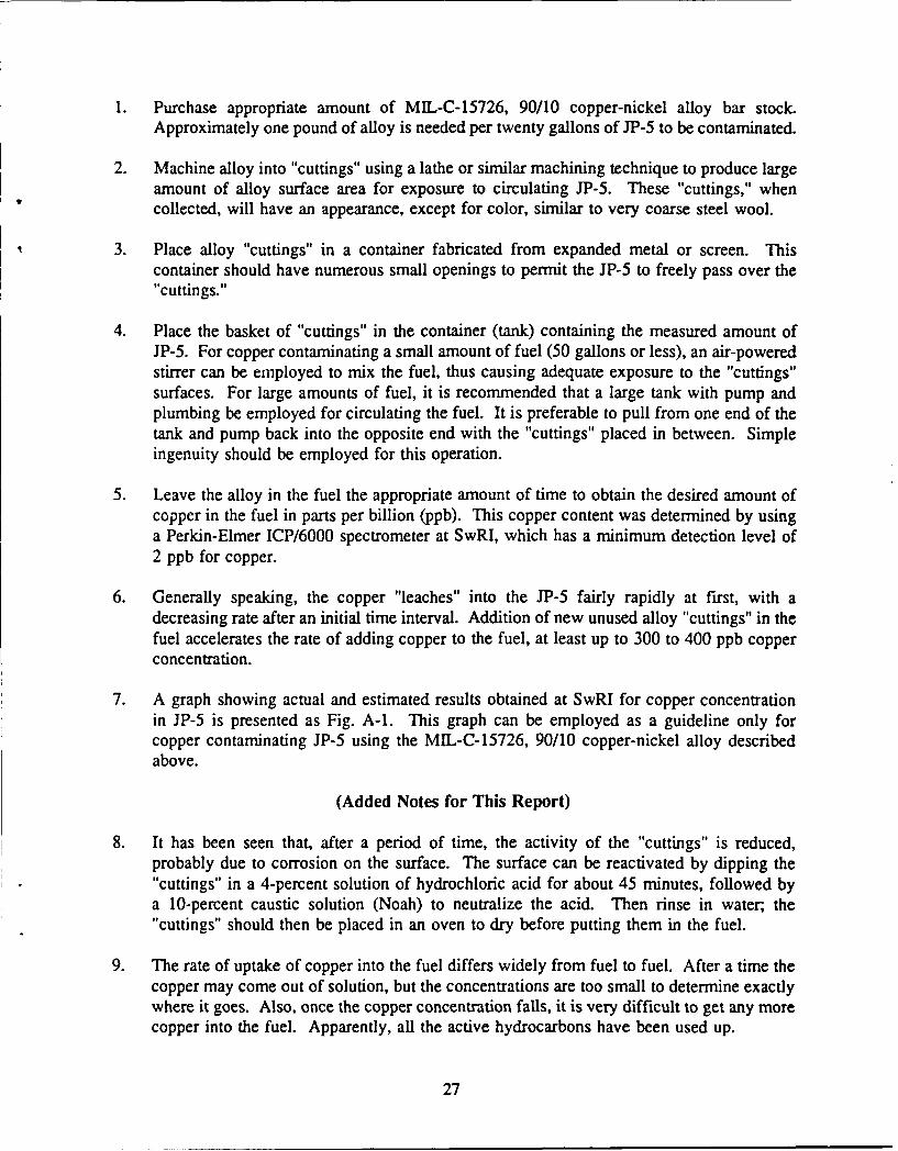
7. A graph showing actual and estimated results obtained at SwRI for copper concentrationin JP-5 is presented as Fig. A-1. This graph can be employed as a guideline only forcopper contaminating JP-5 using the MIL-C-15726, 90/10 copper-nickel alloy describedabove.
(Added Notes for This Report)
8. It has been seen that, after a period of time, the activity of the "cuttings" is reduced,probably due to corrosion on the surface. The surface can be reactivated by dipping the"cuttings" in a 4-percent solution of hydrochloric acid for about 45 minutes, followed bya 10-percent caustic solution (Noah) to neutralize the acid. Then rinse in water, the"cuttings" should then be placed in an oven to dry before putting them in the fuel.
9. The rate of uptake of copper into the fuel differs widely from fuel to fuel. After a time thecopper may come out of solution, but the concentrations are too small to determine exactlywhere it goes. Also, once the copper concentration falls, it is very difficult to get any morecopper into the fuel. Apparently, all the active hydrocarbons have been used up.
27

0
C
00
CLL
0,0
cn Z C:Wo a"0
Co 3:*0
Z U) u)
0
LO.
0 a C0
0r 0 0' 0 0n 0 0 0K), q (N CN V- V
(qdd) uo!ilI!6 .ed SPJDd U! peppV ieddoZ)
28

DISTRIBUTION LIST
Department of Defense
DEFENSE TECHNICAL INFORMATION CTR OFC DEP SEC DEF FOR RSCH & ENGRCAMERON STATION 12 ATTN: DUSDRE/RAT (DR DIX)ALEXANDRIA VA 22314 WASHINGTON DC 20301-8000
OFC ASST SEC DEE FOR PRODUCTION & DEFENSE ADVANCED RSCH PROJECTS AGYLOGISTICS DEFENSE SCIENCES OFFICE I
ATIrN: L/EP (MR DYCKMAN) 1 3701 NORTH FAIRFAX DRIVEWASHINGTON DC 20301-8000 ARLINGTON VA 22203-1714
CDR DEFENSE STANDARDIZATION OFFICEDEFENSE FUEL SUPPLY CENTER AITN: DR S MILLERATTN: DFSC-Q (MR MARTIN) 1 5203 LEESBURG PIKE, SUITE 1403CAMERON STATION FALLS CHURCH VA 22041ALEXANDRIA VA 22304-6160
Department of the Army
CDR CDRUS ARMY BELVOIR RESEARCH. US ARMY NATICK RD&E CENTER
DEVELOPMENT AND ENGINEERING CTR ATTN: SATNC-UATUN: SATBE-F I NATICK MA 01760-5020
SATBE-FL 10SATBE-BT 2 DIRECTORSATBE-TQ 1 AVIATION APPLIED TECH DIRSATBE-PEC (MR COOK) 1 US ARMY R&T ACTIVITY (AVSCOM)
FORT BELVOIR VA 22060-5606 ATTN- SAVRT-TY-ATP (MR MORROW)FORT EUSTIS VA 23604-5577
HQ, DEPT OF THE ARMYATTN: DALO-TSE (COL HOLLEY) 1 CDRWASHINGTON DC 20310-0561 US ARMY RESEARCH OFFICE
ATTIN: SLCRO-EG (DR MANN) ICDR SLCRO-CB IUS ARMY TANK-AUTOMOTIVE COMMAND RSCH TRIANGLE PARK NC 27709-2211ATTN: AMSTA-RG (DR MCCLELLAND) 1
AMSTA-RGD 1 CDRAMSTA-RGR (DR BRYZIK) 1 US ARMY FOREIGN SCIENCE & TECH CTR
WARREN MI 48397-5000 ATTN: AIAST-RA-ST3 (MR BUSI)220-7TH STREET NE
CDR CHARLOTTESVILLE VA 22901US ARMY LABORATORY COMMANDATTN: AMSLC-TP-PB 1 PROJECT MANAGERADELPHI MD 20783-1145 PETROLEUM & WATER LOGISTICS
ATTN: AMCPM-PWLDOD PROJ MGR, MOBILE ELECTRIC POWER 4300 GOODFELLOW BLVDUS ARMY TROOP SUPPORT COMMAND ST LOUIS MO 63120-1798ATTN: AMCPM-MEP-TM (MR WADSI) 17500 BACKLICK ROADSPRINGFIELD VA 22150
BFLRF No. 281Page 1 of 4

CDR HQ, US ARMY ARMOR CENTERUS ARMY PETROLEUM CENTER ATTN: ATSB-CD-MLATrN: SATPC-Q (MR ASHBROOK) 1 ATSB-TSM-T
SATPC-QR 1 FORT KNOX KY 40121SATPC-QE, BLDG 85-3
(MR GARY SMITH) 1 CDRNEW CUMBERLAND PA 17070-5008 US ARMY QUARTERMASTER SCHOOL
ATTN: ATSM-CDM (MR C PARENT) ICDR ATSM-PWD (LTC GIBBONS) IUS PETROLEUM FIELD OFFICE WEST FORT LEE VA 23801ATTN: SATPC-QW (MR ECCLESTON) 1DDRW, BLDG 247, TRACEY LOCATION CDRP 0 BOX 96001 US ARMY COMBINED ARMS & SUPPT CMDSTOCKTON CA 95296-0960 AND FT LEE
ATTN: ATCL-CD ICDR ATCL-MS IUS ARMY RSCH, DEV & STDZN GROUP (UK) FORT LEE VA 23801-6000ATTN: AMXSN-UK-RA
(DR REICHENBACH) 1 CDRBOX 65 US ARMY INFANTRY SCHOOLFPO NEW YORK 09510-1500 ATTN: ATSH-CD-MS-M
FORT BENNING GA 31905-5400CDR, US ARMY AVIATION SYSTEMS CMDATTN: AMSAV-EP 1 CDR4300 GOODFELLOW BLVD US ARMY AVIATION CTR & FT RUCKERST LOUIS MO 63120-1798 ATTN: ATZQ-DI
FORT RUCKER AL 36362CDRUS ARMY YUMA PROVING GROUND CHIEFATTN: STEYP-MT-TL-M 1 US ARMY LOGISTICS ASSISTANCEYUMA AZ 85364-9103 OFFICE, LAO-CONUS
ATIN: AMXLA-COCDR FORT MCPHERSON GA 30330-6000US ARMY EUROPE & SEVENTH ARMYATTIN: AEAGG-FMD 1 CDRAPO NEW YORK 09403 US ARMY ENGINEER SCHOOL
ATTN. ATSE-CDPROGM EXEC OFF, CLOSE COMBAT FORT LEONARD WOOD MO 65473-5000APEO SYSTEMS, ATIN: SFAE-ASM-S IPM ABRAMS, ATTN: SFAE-ASM-AB 1 HQ, EUROPEAN COMMANDPM BFVS, ATTN: SFAE-ASM-BV 1 ATTN: ECJ4/LIJ (LTC CUMBERWORTH)US ARMY TANK-AUTOMOTIVE COMMAND VAIHINGEN, GEWARREN MI 48397-5000 APO NEW YORK 09128
HQUS ARMY TRAINING & DOCTRINE CMDATTN: ATCD-SL-5 1FORT MONROE VA 23651-5000
BFLRF No. 281Page 2 of 4

Department of the Navy
CDR CDRNAVAL SEA SYSTEMS COMMAND NAVAL AIR SYSTEMS COMMANDATTN: CODE 05M32 (MR DEMPSEY) 1 ATTN. CODE 53632F (MR MEARNS)WASHINGTON DC 20362-5101 WASHINGTON DC 20361-5360
CDR CDRDAVID TAYLOR RESEARCH CENTER NAVAL RESEARCH LABORATORYATrN: CODE 2759 (MR STRUCKO) 1 ATIN: CODE 6180ANNAPOLIS MD 21402-5067 WASHINGTON DC 20375-5000
CDR US MARINE CORP LIAISONNAVAL AIR WARFARE CENTER AIRCRAFT Al~rN: USMC-LNO (MAJ OT7O)
DIVISION US ARMY TANK-AUTOMOTIVE COMMANDATrN: PE-33 (MR D'ORAZIO) 1 (TACOM)
PE-33 (MR R KAMIN) 10 WARREN MI 48397-5000P 0 BOX 7176TRENTON NJ 06828-0176 DEPUTY COMMANDING GENERAL
USMC RD&A COMMANDCDR ATTN: PM GND WEAPONS (CB6T),NAVAL PETROLEUM OFFICE LTC VARELLAATTN: CODE 40 (MR LONG) 1 SSEA (LTC PHILLIPS)CAMERON STATION QUANTICO VA 22134-5080ALEXANDRIA VA 223Y-t-6180
OFFICE OF CHIEF OF NAVAL RESEARCHATTN: OCNR-12E (DR ROBERTS) 1ARLINGTON VA 22217-5000
DEPiRTMENT OF THE NAVYHQ, US MARINE CORPSAITTN: LPP-2 (MAJ TALLERI) 1WASHINGTON DC 20380
Department of the Air Force
CDR HQ, US AIR FORCESAN ANTONIO AIR LOGISTICS CTR ATTN: LEYSFATTIN: SAALC/SFT (MR MAKRIS) I WASHINGTON DC 20330
SAALC/LDPE (MR ELLIOT) 1KELLY AIR FORCE BASE TX 78241 CDR
US AIR FORCE WRIGHT AERO LABCDR ATUN: POSF (MR DELANEY)DET 29 WRIGHT-PATIERSON AFB OH 45433-6563ATIN: SA-ALC/SFM 1CAMERON STATIONALEXANDRIA VA 22304-6179
BFLRF No. 281Page 3 of 4

Other Organizations
NATIONAL AERONAUTICS AND SPACE DEPT OF TRANSPORTATIONADMINISTRATION FEDERAL AVIATION ADMINISTRATION
LEWIS RESEARCH CENTER AWS-I10CLEVELAND OH 44135 800 INDEPENDENCE AVE, SW
WASHINGTON DC 20590
DEPARTMENT OF ENERGY
CE-151, ATrN: MR JOHN RUSSELL1000 INDEPENDENCE AVE, SWWASHINGTON DC 20585
BFLRF No. 281Page 4 of 4