Embed Size (px)
Citation preview
EFFECT OF AMBIENT TEMPERATURE ON THE PERFORMANCE OF
COMBINED CYCLE POWER PLANT WITH COOLING SYSTEM IN A
SUBTROPICAL REGION
HAYDER BAQER MAHDI
Thesis submitted in partial fulfilment of the requirements
For the award of the degree of
Master of Engineering (Mechanical Engineering)
FACULTY OF MECHANICAL ENGINEERING
UNIVERSITI MALAYSIA PAHANG
February 2016
vi
ABSTRACT
The climate conditions have a powerful influence on combined cycle power plant
performance as its known. Total output power and overall thermal efficiency of the
power plant dropping under the high ambient temperatures that often occur during the
hot days. This is a major drawback for combined cycle power plant operated in a
subtropical region. In the Middle East where this study was carried out, the ambient
temperature typically varies between (15C) and (45C). The Plant has been studied
consist of three gas turbines with total power (535MW) and three triple-pressure heat
recovery steam generators, addition one steam turbine with (345 MW) output power.
The overall thermal efficiency of power plant is (57.7%). In this study, combined cycle
power plant was used for assessment of the performance with the changes in ambient air
temperature. Two approaches were used to study this phenomenon. Firstly, the
performance parameters were calculated by using actual data acquired by the operation
history of the power plant. Secondly, the performance was analyzed using
thermodynamic principles. Then results of the two approaches were compared and
optimizing using RBFNN method. Cooling the gas turbine inlet air can improve the
power plant performance substantially. This occurs due to the cooled air is denser,
giving the compressor a higher mass flow rate and resulting in increased output power
and efficiency of the power plant. Single effect LiBr absorption chiller proposed as a
cooling system to cool the ambient air temperature at (15 C). The average reduction in
power output per degree Celsius is about (1.82 MW). Cooling of inlet air from (45°C)
down to (15°C) would increase the power output around (50.04MW). Where every
decline in temperature by (10°C) adding to the total output power of (16 MW). The
average reduction in the overall thermal efficiency per degree Celsius is about
(0.217%). In addition, the cooling of inlet air from (45°C) down to (15°C) would
increase the overall thermal efficiency around (6.091%). Where every decline in the
temperature by (10°C), that increases the overall thermal efficiency around (2.03%).
The results of using this cooling technique are increasing the total output power and
overall thermal efficiency to (875 MW), (58%) respectively. The effect of using radial
basis function neural network (RBFNN) technique give the average deviation about
(1.2%) and (1.7%) for the power output and thermal efficiency respectively.

vii
ABSTRAK
Keadaan iklim mempunyai pengaruh yang kuat ke atas gabungan prestasi loji janakuasa
kitar seperti yang diketahui. Jumlah kuasa output dan kecekapan keseluruhan haba loji
kuasa menjatuhkan bawah suhu ambien yang tinggi yang sering berlaku pada hari-hari
panas. Ini adalah kelemahan utama bagi loji tenaga kitaran beroperasi di kawasan yang
subtropika. Di Timur Tengah di mana kajian ini dijalankan, suhu ambien biasanya
berbeza-beza antara (15C) dan (45C). Loji telah dikaji terdiri daripada tiga turbin gas
dengan jumlah kuasa (535 MW) dan tiga penjana pemulihan haba wap tekanan tiga kali
ganda, tambahan satu turbin stim dengan (345 MW) kuasa keluaran. Kecekapan
keseluruhan haba loji kuasa (57.7%). Dalam kajian ini, loji tenaga kitaran telah
digunakan untuk penilaian prestasi dengan perubahan dalam suhu udara ambien. Dua
pendekatan telah digunakan untuk mengkaji fenomena ini. Pertama, parameter prestasi
dikira dengan menggunakan data sebenar yang diperolehi oleh sejarah operasi loji
janakuasa. Kedua, prestasi dianalisis menggunakan prinsip termodinamik. Maka
keputusan kedua-dua pendekatan telah dibandingkan dan mengoptimumkan
menggunakan kaedah RBFNN. Penyejukan udara masuk turbin gas boleh meningkatkan
prestasi loji kuasa dengan ketara. Ini berlaku kerana udara sejuk adalah lebih padat,
memberikan pemampat kadar aliran jisim yang lebih tinggi dan menyebabkan
peningkatan kuasa keluaran dan kecekapan loji kuasa. Single kesan LIBR penyejuk
penyerapan dicadangkan sebagai sistem penyejukan untuk menyejukkan suhu udara
ambien di (15 C). Pengurangan purata kuasa output per darjah Celsius adalah kira-kira
(1.82 MW). Penyejukan udara masuk dari (45 ° C) ke (15 ° C) akan meningkatkan
output kuasa sekitar (50.04MW). Di mana setiap penurunan suhu dengan (10 ° C)
menambah kepada jumlah kuasa keluaran (16 MW). Pengurangan purata kecekapan
haba keseluruhan per darjah Celsius adalah kira-kira (0,217%). Di samping itu,
penyejukan udara masuk dari (45 ° C) ke (15 ° C) akan meningkatkan kecekapan
keseluruhan haba sekitar (6,091%). Di mana setiap penurunan suhu oleh (10 ° C), yang
meningkatkan kecekapan keseluruhan haba sekitar (2.03%). Keputusan menggunakan
teknik ini penyejukan semakin meningkat jumlah kuasa keluaran dan kecekapan haba
keseluruhan (875 MW), (58%) masing-masing. Kesan penggunaan rangkaian neural
teknik jejarian fungsi asas (RBFNN) memberi sisihan purata kira-kira (1.2%) dan
(1.7%) untuk output kuasa dan kecekapan haba masing-masing.
viii
CONTENTS
Page
SUPERVISORS' DECLARATION ii
STUDENT'S DECLARATION iii
ACKNOWLEDGEMENTS v
ABSTRACT vi
ABSTRAK vii
CONTENTS viii
LIST OF TABLES xi
LIST OF FIGURES xi
NOMENCLATURES xiv
LIST OF ABBREVIATIONS xvii
CHAPTER I INTRODUCTION
1.1 Introduction 1
1.2 Problem Statement 5
1.3 Objectives of the Study 6
1.4 Methodology 6
1.5 Scope of the Study 7
1.6 Thesis Outline 8
CHAPTER II LITERATURE REVIEW
2.1 Introduction 9
2.2 Ambient Temperature Effect 9
2.3 Background and Past Work 11
2.4 Economic Criteria for Inlet Cooling 16
2.5 Methods of Cooling the Inlet Air for Gas Turbine in Combined
Cycle Power Plants
17
2.5.1 Water Evaporation Systems 18
2.5.2 Evaporative Cooler 18
2.5.3 Evaporative Cooling of Pre-Compressed Air 21
2.5.4 Fogging System 22
ix
2.5.5 Heat Transfer Systems 25
2.5.6 Mechanical Refrigeration System with Chilled Water
Storage
25
2.5.7 Mechanical Refrigeration System with Ice Storage 27
2.5.8 Lithium-Bromide Absorption Chiller 29
2.6 Summary 35
CHAPTER III METHODOLOGY
3.1 Introduction 36
3.2 Power Plant Description 36
3.3 Strategy Of Work Frame 37
3.4 Thermodynamic Approach on the Combined Cycle 38
3.4.1 Ideal Brayton Cycle
38
3.4.2 Modelling of Actual Gas Turbine Cycle
40
3.4.3 Ideal Rankine Cycle
45
3.4.4 Heat Recovery Steam Generator (HRSG 47
3.4.5 Steam Turbine 55
3.5 Modelling of Cooling Cycle System (Single-Effect Libr-Water
Absorption Chiller)
57
3.5.1 Air Heat Exchanger
60
3.5.2 Evaporator
61
3.5.3 Expansion Valve
62
3.5.4 Condenser
62
3.5.5 Solution Heat Exchanger 63
3.5.6 Generator
64
3.5.7 Absorber
64
3.5.8 Pump
65
3.5.9 Throttle Valve 66
3.6 Optimization Technique 66
3.6.1 RFBNN Optimization Technique 67
3.6.2 RBFNN Structure
67
3.7 Summary 69

x
CHAPTER IV RESULTS AND DISCUSSION
4.1 Introduction 70
4.2 Analysis the Ambient Temperature Effect 70
4.3 Analysis the Cooling System Results 80
4.4 Optimization Results 87
4.5 Summary 89
CHAPTER V CONCLUSIONS AND RECOMMENDATIONS
5.1 Introduction 90
5.2 Total Output Power of Power Plant 90
5.3 Overall Thermal Efficiency of Power Plant 91
5.4 Specific Fuel Consumption 92
5.5 Recommendations for Future Work 92
REFERENCES 93
APPENDIX
A MATLAB Codes for RBFNN Optimization Technique 99
xi
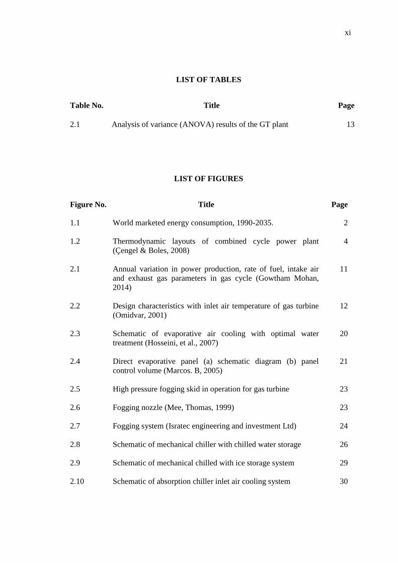
LIST OF TABLES
Table No. Title Page
2.1 Analysis of variance (ANOVA) results of the GT plant
13
LIST OF FIGURES
Figure No. Title Page
1.1 World marketed energy consumption, 1990-2035.
2
1.2 Thermodynamic layouts of combined cycle power plant
(Çengel & Boles, 2008)
4
2.1
Annual variation in power production, rate of fuel, intake air
and exhaust gas parameters in gas cycle (Gowtham Mohan,
2014)
11
2.2 Design characteristics with inlet air temperature of gas turbine
(Omidvar, 2001)
12
2.3 Schematic of evaporative air cooling with optimal water
treatment (Hosseini, et al., 2007)
20
2.4 Direct evaporative panel (a) schematic diagram (b) panel
control volume (Marcos. B, 2005)
21
2.5 High pressure fogging skid in operation for gas turbine 23
2.6 Fogging nozzle (Mee, Thomas, 1999) 23
2.7 Fogging system (Isratec engineering and investment Ltd) 24
2.8 Schematic of mechanical chiller with chilled water storage 26
2.9 Schematic of mechanical chilled with ice storage system 29
2.10 Schematic of absorption chiller inlet air cooling system
30
xii
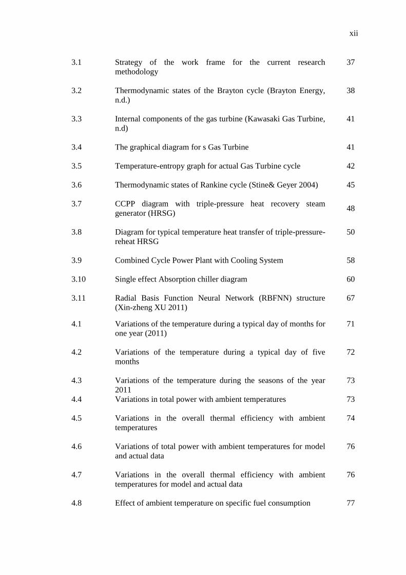
3.1 Strategy of the work frame for the current research
methodology
37
3.2 Thermodynamic states of the Brayton cycle (Brayton Energy,
n.d.)
38
3.3 Internal components of the gas turbine (Kawasaki Gas Turbine,
n.d)
41
3.4 The graphical diagram for s Gas Turbine 41
3.5 Temperature-entropy graph for actual Gas Turbine cycle 42
3.6 Thermodynamic states of Rankine cycle (Stine& Geyer 2004) 45
3.7 CCPP diagram with triple-pressure heat recovery steam
generator (HRSG) 48
3.8 Diagram for typical temperature heat transfer of triple-pressure-
reheat HRSG
50
3.9 Combined Cycle Power Plant with Cooling System 58
3.10 Single effect Absorption chiller diagram 60
3.11 Radial Basis Function Neural Network (RBFNN) structure
(Xin-zheng XU 2011)
67
4.1 Variations of the temperature during a typical day of months for
one year (2011)
71
4.2 Variations of the temperature during a typical day of five
months
72
4.3 Variations of the temperature during the seasons of the year
2011
73
4.4 Variations in total power with ambient temperatures 73
4.5 Variations in the overall thermal efficiency with ambient
temperatures
74
4.6 Variations of total power with ambient temperatures for model
and actual data
76
4.7 Variations in the overall thermal efficiency with ambient
temperatures for model and actual data
76
4.8 Effect of ambient temperature on specific fuel consumption 77
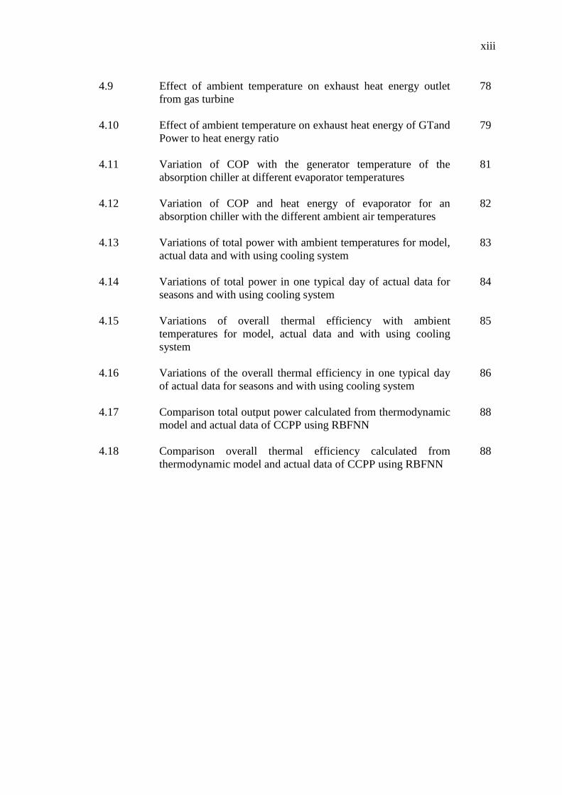
xiii
4.9 Effect of ambient temperature on exhaust heat energy outlet
from gas turbine
78
4.10 Effect of ambient temperature on exhaust heat energy of GTand
Power to heat energy ratio
79
4.11 Variation of COP with the generator temperature of the
absorption chiller at different evaporator temperatures
81
4.12 Variation of COP and heat energy of evaporator for an
absorption chiller with the different ambient air temperatures
82
4.13 Variations of total power with ambient temperatures for model,
actual data and with using cooling system
83
4.14 Variations of total power in one typical day of actual data for
seasons and with using cooling system
84
4.15 Variations of overall thermal efficiency with ambient
temperatures for model, actual data and with using cooling
system
85
4.16 Variations of the overall thermal efficiency in one typical day
of actual data for seasons and with using cooling system
86
4.17 Comparison total output power calculated from thermodynamic
model and actual data of CCPP using RBFNN
88
4.18 Comparison overall thermal efficiency calculated from
thermodynamic model and actual data of CCPP using RBFNN
88
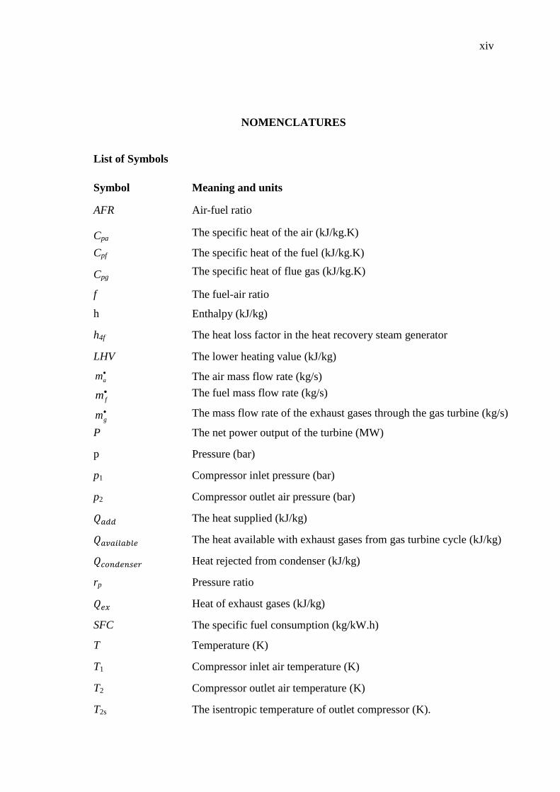
xiv
NOMENCLATURES
List of Symbols
Symbol Meaning and units
AFR Air-fuel ratio
Cpa The specific heat of the air (kJ/kg.K)
Cpf The specific heat of the fuel (kJ/kg.K)
Cpg The specific heat of flue gas (kJ/kg.K)
f The fuel-air ratio
h Enthalpy (kJ/kg)
h4f The heat loss factor in the heat recovery steam generator
LHV The lower heating value (kJ/kg)
am The air mass flow rate (kg/s)
fm
The fuel mass flow rate (kg/s)
gm The mass flow rate of the exhaust gases through the gas turbine (kg/s)
P The net power output of the turbine (MW)
p Pressure (bar)
p1 Compressor inlet pressure (bar)
p2 Compressor outlet air pressure (bar)
The heat supplied (kJ/kg)
The heat available with exhaust gases from gas turbine cycle (kJ/kg)
Heat rejected from condenser (kJ/kg)
rp Pressure ratio
Heat of exhaust gases (kJ/kg)
SFC The specific fuel consumption (kg/kW.h)
T Temperature (K)
T1 Compressor inlet air temperature (K)
T2 Compressor outlet air temperature (K)
T2s The isentropic temperature of outlet compressor (K).

xv
Ta The average temperature (T2+T1)/2 (K)
Tap The approach points (K)
Tf The temperature of fuel (K)
Tpp The pinch point (K)
Ts The saturation steam temperature (K)
Tw1 The temperature of water entering the economizer (K)
Tw2 The temperature of water entering the evaporator (K)
vf Specific volume of the water (m3/kg)
Wcomp The work of the compressor (kJ/kg)
WGTnet The net work of the gas turbine (kJ/kg)
Wpump The work of the pump (kJ/kg)
WSTnet The work net of the steam turbine cycle (kJ/kg)
W The work of the steam turbine (kJ/kg)
WST The shaft work of the turbine (kJ/kg)
Greek Symbols
Symbol Meaning
ε Effectiveness of the regenerative heat exchanger
ρ Density (kg/m3)
k Specific heat ratio
Specific heat ratio of air
Specific heat ratio of gases
Efficiency
Isentropic compressor efficiency
chp The high-pressure compressor efficiency
clp The low-pressure compressor efficiency
HPT The high-pressure turbine efficiency
LPT The low-pressure turbine efficiency
The mechanical efficiency of the compressor and turbine
p The water pump efficiency

xvi
The steam turbine efficiency
Overall efficiency of CCPP
Thermal Brayton cycle efficiency
th The thermal efficiency of the gas turbine
Subscripts
Symbol Meaning
1,2…etc State number
a Air
add Added
ap Approach point
av Average
comp Compressor
cond Condenser
f Fuel
g Gases
GTnet Gas turbine net work
HP High pressure
IP Intermediate pressure
LP Low pressure
p pump
pp Pinch point
s Saturated steam
STnet Steam turbine work net
ss Superheated steam
ST Steam turbine
w Water
w1 Inlet water to economizer
w2 Inlet water to evaporator
xvii
LIST OF ABBREVIATIONS
Comp Compressor
C.C Combustion chamber
CCPP Combined cycle gas turbine power plant
D Drum
GT Gas turbine
HE Heat exchanger
HPST High pressure turbine
HRSG Heat recovery steam generator
IEA International Energy Agency
IP Intermediate pressure
IPST Intermediate pressure turbine
ISO International standards organization
LHV Lower Heating Value
LP low pressure
LPST Low pressure turbine
SFC Specific fuel consumption
ST Steam turbine
TIT Turbine inlet temperature
1
CHAPTER ONE
INTRODUCTION
1.1 INTRODUCTIONS
When the industrial revolution is starting, people become more and more
dependent on hydrocarbon fuels for the generation of power. Now around (85%) of the
energy requirements of the almost counties are supplied by fossil fuels. The increasing
combustion of fossil fuels and associated carbon dioxide (CO2) emissions are creating
concerns about climate change. One of the most significant and innovative solutions
that reduce greenhouse gas emissions and an increase in generated net power with
characterized as high efficiency is a combined cycle power plant (CCPP).
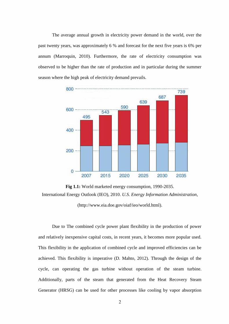
Grows energy consumption of the world marketed by (49) percent from (2007 to
2035) (IEO, 2010). The total energy use in the world rises from (495) quadrillions
British thermal units (Btu) in (2007) to (590) quadrillions Btu in (2020) and (739)
quadrillions Btu in (2035) as shown in Figure 1.1 (IEO, 2010) an increase of over (6%)
per annum (Sepehr Sanjay, 2011). The global economic downturn which started in
(2007) and non-stop until (2015) has had a profound shock on world energy
requirement in the near expression. With the fall in demand among both manufacturers
and consumers came a decline in total global marketed energy consumption by (1.2)
percent in (2008) and by (2.2) percent in (2009) (IEO, 2010).
2
The average annual growth in electricity power demand in the world, over the
past twenty years, was approximately 6 % and forecast for the next five years is 6% per
annum (Marroquin, 2010). Furthermore, the rate of electricity consumption was
observed to be higher than the rate of production and in particular during the summer
season where the high peak of electricity demand prevails.
Fig 1.1: World marketed energy consumption, 1990-2035.
International Energy Outlook (IEO), 2010. U.S. Energy Information Administration,
(http://www.eia.doe.gov/oiaf/ieo/world.html).
Due to The combined cycle power plant flexibility in the production of power
and relatively inexpensive capital costs, in recent years, it becomes more popular used.
This flexibility in the application of combined cycle and improved efficiencies can be
achieved. This flexibility is imperative (D. Mahto, 2012). Through the design of the
cycle, can operating the gas turbine without operation of the steam turbine.
Additionally, parts of the steam that generated from the Heat Recovery Steam
Generator (HRSG) can be used for other processes like cooling by vapor absorption
3
chiller, distillation the sea water and other application, also, to run the steam turbine.
Furthermore, by burning additional natural gas in the HRSG can increase the power
generation during hours of peak demand. However, the gas and steam turbines have
individually efficiencies around (40%), while, and operated together in the combined
cycle system, thermal efficiencies can attain 60% of the LHV (D.L. Chase 2000).
The combined cycle power plant (CCPP) combines two thermodynamic cycles,
the Rankine cycle for steam turbine and the Brayton cycle for a gas turbine, to generate
power efficiently. And these combinations Brayton cycle of the gas turbine and
Rankine cycle the steam power system complement each other to form efficient
combined-cycles. The Brayton cycle has high source temperature and rejects heat at a
temperature that conveniently used as the energy source for the Rankine cycle. In other
words, practically in the gas turbine not converted all the energy that come from the
combustion of fuel (Natural Gas and Air) to shaft power. The residual energy released
as waste heat in the flue gas, the exhaust heat may be used in various ways. If exhaust
heat is used to produce steam in a waste heat boiler for a steam turbine, with the object
of augmenting the shaft power produced, the system is called combined gas/steam
cycle. The only limitation is the exhaust (stack) temperature (Çengel & Boles, 2008)
The most commonly used working fluids for combined cycles are air and steam;
other working fluids (organic fluids, potassium vapor, mercury vapor, and others) have
been applied on a limited scale. Combined-cycle systems that utilize steam and air
working fluids have achieved widespread commercial application (Çengel & Boles,
2008). Usually, in typical plant drive combine one or more than gas turbines, almost
4
cases run three gases turbines. Also consisting of other major components are steam
turbines, heat recovery steam generators (HRSG), and generators to produce electricity.
The fuel used in the combined cycle power plant is natural gas has several
advantages in use, it is a clean has less than emissions of CO2, and other greenhouses
produce from burn Fossil fuel in the conventional power plant. Leading to significantly
participate in reduced emissions of (CO2) to climate, also cheap is as available in the
region of plant use, safe and easy to use and easy to deliver the type of fuel among all
energy sources. The optimally combined cycle power plants categorized by minimum
specific yearly cost values. Recent Improvements on gas turbine have led to extensive
use of combined power plant for electrical generation power and made it possible to
reach a thermal efficiency of (55–60%) (S. Boonnasaa, 2004). The optimally combined
cycle power plants characterized by minimum specific annual cost values (Çengel &
Boles, 2015).
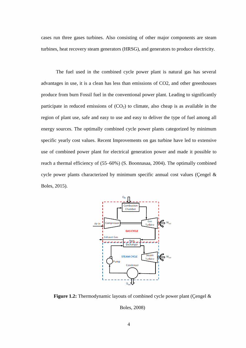
Figure 1.2: Thermodynamic layouts of combined cycle power plant (Çengel &
Boles, 2008)
5
As shown in Figure 1.2, fuel (natural gas) is burned with air in the combustion
chamber for the gas turbine. The energy release from the combustion operation makes
the turbine is rotating. This rotation produces work used to turn the generator and
produce electricity. The modern gas turbines have efficiency around (40%). (Çengel &
Boles, 2008)
The exhaust gasses are hot of the gas turbine are used to create steam for the
steam cycle, by using heat recovery steam generation (HRSG). This steam provides to
get more work from a steam turbine. Also, the steam turbine will be rotating and
produces work and using to generating addition power. Furthermore, if steam desired
for other processes, some of the steam generated from the HRSG can be removed from
the steam cycle (Nicola Palestra, 2008). The combined cycle power plants are typically
artificial with standard components, which are combined to meet specific user needs
(Naradasu, 2007). These plants can be operated by a variation of fuels, containing
natural gas, fuel oils, as well as gasified coal.
1.2 PROBLEM STATEMENT
One of the major drawbacks of the combined cycle power plant (CCPP)
operating in subtropical countries is the rapid performance drop when ambient air
temperature increases (S. Boonnasaa, 2004). In the area where the Combined Cycle
Power Plant considered for this study is located the ambient air temperature varies
between (1 C) and ( C) during the day and also varies along the year, which has also
been recorded in the past data acquired from the power station. From the daily readings
of the particular combined cycle power plant located subtropical country, it can be
6
noticed that full load capacity drops during hot daytime with about (1-2 MW) out of the
overall output achieved in morning and night hours (Guoqiang Zhang, 2014).
1.3 OBJECTIVES
The purposes of this study are summarized as follows:
To develop an integrated thermodynamic model based on thermodynamic
analysis for enhancing the performance of combined cycle power plant and to
the cooling system.
To investigate the impact of operating particular variable (ambient air
temperature) on combined cycle power plant for improving the thermal
efficiency and power output.
To optimum the thermal efficiency different and other parameter involved in the
performance of the combined cycle power plant to obtain the optimum
performance based on thermodynamic analysis
1.4 METHODOLOGY
The primary object of this research is a focus on the investigation of the cooling
system for the inlet air to the gas turbine of combined cycle power plant. As the first
step, a literature survey was carried out to study the inlet cooling methods, advantages,
disadvantages of specific methods, theoretical background of the inlet cooling and the
combined cycle power plant operation. Analysis and discuss the relationship between
an inlet air cooling system with combined cycle performance.
7
A combined cycle power plant located in subtropical was used for evaluating the
performance with the changes in the ambient air temperature. Two approaches have
been applied to study this phenomenon. Firstly, changes were calculated by actual data
acquired by the operation history of the power plant. The required data needed for the
analysis obtained from the data sheets of the power plant and the machine manuals.
These analyzed data given a determining of the patterns performance variations
with air temperature. Secondly, the performance was analyzed using thermodynamic
principles. Then the results of the two approaches are compared. In the next phase,
energy calculations were performed to obtain the required level of the charge air
cooling and to select a suitable capacity of an absorption chiller.
1.5 SCOPES
This research seeks to improve the overall performance of the combined cycle power
plants by using a cooling system. The scope of the study is outlined as follows:
The thermodynamic model is developed to estimate the performance of the
combined cycle power plant for various ambient temperature ranges from 15 ºC
to 45 ºC.
The effect of one operation parameter (ambient temperature) on the performance
of power plants.
The energy analysis by using the first law of thermodynamics to measure the
performance of the combined cycle power plant adopted, While, the fluid flow
and aerodynamics and exergy analysis are out of the scope.

8
The study models are evaluated based on the actual data of real combined cycle power
plants through a typical year in the subtropical region.
1.6 THESIS OUTLINE
The thesis is organized as follows:
Chapter 2: Introduce the effect of one operation parameter ( ambient temperature) on
the performance of combined cycle power plant. A review of the past work in cooling
techniques has been covered.
Chapter 3: In this chapter, the thermal analysis CCPP performance of actual data and
thermodynamic model were presented. Also, optimize the CCPP performance by using
RBFNN optimization technical.
Chapter 4: This chapter describes the results of a CCPP performance actual data,
model, with and without using the cooling system. Moreover, the optimization results
with use RBFNN. Comparison graphs were implemented to compare the result of using
the cooling system. The performance of Absorption chiller as a cooling system
presented with the ambient temperature varying.
Chapter 5: This chapter summarizes and highlights the contributions of the thesis,
followed by future directions of research.
9
CHAPTER TWO
LIT ERATURE REVIEW
2.1 INTRODUCTION
This chapter reviews a comprehensive knowledge of past research efforts of
cooling inlet air to gas turbine of combined cycle power plant. Over the past periods,
many studies conducted to improve the performance of combined cycle power plant.
Some of these studies have focused on inlet air cooling systems of the gas turbine.
However, it is still a small number of studies in this domain. Therefore, the current
study focused on detailed review the past work of cooling system methods.
2.2 AMBIENT TEMPERATURE EFFECT
Is well recognized, that the performance of the gas turbine (GT) in combined
cycle power plants depends largely on the ambient conditions especially, the decline in
power production is the result of the higher air temperature. Inlet air temperature to the
gas turbine is an effective factor in increasing the performance of the gas turbine
(Brayton cycle) (Thamir K. Ibrahim, 2010). A decrease the temperature of inlet air can
significantly increase the power output of gas turbines. However, this decline in the
temperature of the inlet air increases the fuel consumption rate required to achieve the
required operating temperature at the inlet of the gas turbine. (A. K. Tiwari, 2012)
The mass of the fuel consumption is derived based on the energy balances at the
combustion and reheat chambers. The increasing in fuel consumption has a direct
influence on the flow rate of exhaust gas, and the increased temperature of inlet air
produce a high temperature of flue gases liberated from the gas turbine. That leads to
lower pressure ratios with a rise in temperature air inlet designed to provide a gas
turbine inlet temperature. (Gowtham Mohan, 2014)
10
The increase in the ambient air temperature leads to the falls the air density,
hence at a high temperature of inlet air over (15°C). The mass flow of the air through
the gas turbine has been reduced (Kakaras. E, 2004). As a sequel, the GT output power
is lower, and the net power generated in the combined cycle thermal plant decreases
despite the use of the maximum supplementary firing. Arrieta & Lora 2010 registered
that with a gas temperature of (675°C) after the supplementary firing, the net electric
power varies in the range from (640 to 540 MW) when the ambient temperature varies
between (0°C) and (35°C).
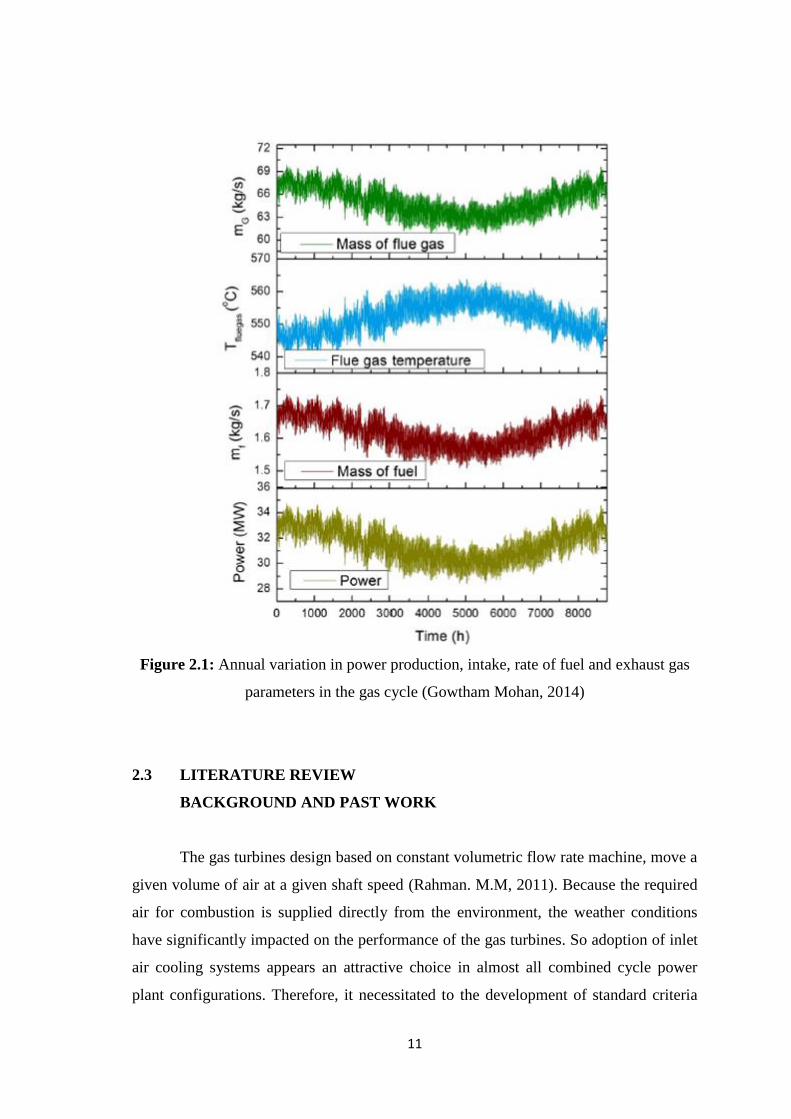
Mohan 2014, in his quest review the performance of the Brayton cycle in the
phrase of the electricity power generation and the mass of fuel consumption is shown in
Figure 2.1. As previously, the temperature of the inlet air is the effective parameter on
the Brayton cycle performance. Mohan, find the output power of the gas cycle reduces
by (12%) in the months of summer. The maximum productivity of (34 MW) achieved
during the winter months. Annual variations in the amount and temperatures of flue
gases are shown in Figure 2.1 (Gowtham Mohan 2014).
During the summer months, the flue gases temperature maximizes, and the
pressure ratio decreases at higher temperatures of the inlet air. The mass flow rate of
exhaust gases liberated from the gas cycle reduced in summer due to the reduction of
fuel consumption and rate of the inlet air (Gowtham Mohan 2014). Also, the power
plant location plays a primary role in its performance. Because the temperature and
humidity of the ambient air and other climatic factors. The atmospheric air which enters
the compressor gets hotter after compression and goes to the combustion chamber(CC).
While in the same year that when ambient temperature increase from (273°K) to
(333°K), the total power output increase about (7%) for all configurations accept the
regenerative gas turbine.
The overall thermal efficiency of the combined cycle which obtained the
maximum value for regenerative gas turbine configuration about (62.8%) at ambient
temperature (273 K). The minimum value of the overall thermal efficiency was about
(53%) of the coolant gas turbine configuration in ambient temperature (333K) (Tiwari.
A.K, 2012).
11
Figure 2.1: Annual variation in power production, intake, rate of fuel and exhaust gas
parameters in the gas cycle (Gowtham Mohan, 2014)
2.3 LITERATURE REVIEW
BACKGROUND AND PAST WORK
The gas turbines design based on constant volumetric flow rate machine, move a
given volume of air at a given shaft speed (Rahman. M.M, 2011). Because the required
air for combustion is supplied directly from the environment, the weather conditions
have significantly impacted on the performance of the gas turbines. So adoption of inlet
air cooling systems appears an attractive choice in almost all combined cycle power
plant configurations. Therefore, it necessitated to the development of standard criteria