Embed Size (px)
Citation preview

Effect of annealing process in water on the essential workof fracture response of ultra high molecular weight polyethylene
Sinan Yilmaz • Taner Yilmaz • A. Armagan Arici
Received: 8 July 2010 / Accepted: 8 October 2010 / Published online: 22 October 2010
� Springer Science+Business Media, LLC 2010
Abstract The toughness of ultra high molecular weight
polyethylene (UHMWPE) before and after annealing pro-
cess in water was investigated by the essential work of
fracture (EWF) method. Annealing in water at 80 �C for
various aging periods of the 5 mm thickness with various
ligament lengths single edge notched tension (SENT)
specimens was performed in hot water. Tensile tests were
performed at 2 mm/min constant deformation rate at room
temperature in order to determine EWF parameters. After
tensile tests, the fracture cross-sections of SENT specimens
were investigated by scanning electron microscope (SEM).
From the 60th day of annealing process in water, it was
seen that the fracture toughness of the material decreased
while water absorption in samples increased.
Introduction
Thermoplastic polymers are widely used in engineering due
to their beneficial properties but the quality of the thermo-
plastic product changes during service. Property degrada-
tion owing to annealing in water may be a severe constraint
for the targeted application. That is the reason why great
efforts are devoted to the stabilization of thermoplastics,
especially for those which are sensitive to environmental
influences. It is known that annealing in water manifests
first in a color change without noticeable effect on the
mechanical properties. Progressing annealing results later in
substantial deterioration of the mechanical characteristics
that is well reflected by the toughness response. Changes in
the toughness of polymers can well be followed by concepts
of the fracture mechanics. Note that a suitable fracture
mechanical method yields a material parameter which does
not depend on the specimen type and dimension [1, 2].
It is well established that when failure of notched
specimens is brittle in nature, the area in which energy is
dissipated near the crack tip is so small that the entire
specimen can be assumed to exhibit Hookean elasticity.
This type of failure can be studied using linear elastic
fracture mechanics (LEFM) [3]. The critical stress intensity
factor (KIc) and critical strain energy release rate (GIc)
proved to be material constants under certain testing con-
ditions that ensure small scale yielding in the specimens.
However, this approach cannot be adopted for toughened
polymers which exhibit gross yielding during fracture. For
the assessment of the fracture toughness of such ductile
polymers, the essential work of fracture (EWF) method is
gaining acceptance due to its experimental simplicity [4].
The EWF assumes that the non-elastic region at the tip of a
crack may be divided into two regions: an inner region
where the fracture process takes place, and the outer region
where the plastic deformation takes place. The total work
of fracture can then be partitioned into two components:
work that is expended in the inner fracture process zone
(IFPZ) to form a neck and subsequent tearing, and the work
which is consumed by various deformation mechanisms in
the surrounding outer plastic deformation zone (OPDZ).
The former is referred to as ‘‘Essential Work of Fracture’’
and the latter as ‘‘Non-Essential Work of Fracture’’ [5, 7].
S. Yilmaz � A. Armagan Arici
Department of Mechanical Engineering, Kocaeli University,
Umuttepe, 41380 Izmit, Turkey
T. Yilmaz (&)
Civil Aviation College, Kocaeli University, Arslanbey Campus,
41285 Izmit, Turkey
e-mail: [email protected]
T. Yilmaz
Natural and Applied Sciences, Kocaeli University,
Umuttepe Campus, 41380 Izmit, Turkey
123
J Mater Sci (2011) 46:1758–1766
DOI 10.1007/s10853-010-4996-0

In this study, EWF approach was used to determine the
fracture toughness of ultra high molecular weight poly-
ethylene (UHMWPE) before and after annealing process in
water. Annealing in water was performed in hot water at
80 �C for 90 days.
EWF
EWF approach, first developed by Broberg [1] is based on
the assumption that the total work of fracture, Wf is the sum
of two energy terms,
Wf ¼ We þWp ð1Þ
where the first term, We, is the EWF, which is the energy
consumed in the IFPZ, where the actual fracture occurs
(see Fig. 1). We is therefore a pure crack resistance
parameter and thus regarded as fracture toughness. The
second term, Wp, which is referred to as the non-essential
work or plastic deformation work, is the energy dissipated
in the OPDZ as shown in Fig. 1, which for polymers
involves microvoiding and shear yielding [7].
When both the IFPZ and the OPDZ contained in the
ligament, then We is proportional to the ligament length,
L and Wp is proportional the square of the ligament length
L2. Hence it can be written as:
We ¼ weTL ð2Þ
Wp ¼ bwpTL2 ð3Þ
where we is termed the specific EWF and bwp is termed the
specific non-EWF. The parameter b is proportionality
constant (plastic zone shape factor) whose value depends
on the geometry of the specimen and the crack [4] but it is
independent of the ligament length, we obtain:
wf ¼ we þ bwpL ð4Þ
where we is termed the ‘‘Specific Essential Work of Frac-
ture (SEWF)’’, wp is termed the ‘‘Specific Non-Essential
Work of Fracture (SNEWF)’’, and wf is the specific total
work of fracture.
To verify how the state of stress may depend on liga-
ment length, values of the maximum net-section stress,
rn ¼ Pmax
LT (where Pmax is the maximum load on the load–
displacement curve) are often plotted against ligament
length, L. Under pure plane stress conditions rn = mry
where m is the plastic constraint factor whose value for
single edge notched tension (SENT) specimen is 1.0 and
for DENT specimen is 1.15. The value of m increases with
the decreasing ligament length [7, 8].
It is also possible to distinguish between the specific
work of fracture for yielding (wy) and the specific work of
fracture for necking and subsequent fracture (wnt). The
specific total work of fracture, wf may thus be written as:
wf ¼ we þ bwpL ¼ wy þ wnt ð5Þ
When Wf is partitioned in this way, variation of the specific
work terms wy and wnt with L follows that of wf with
L. Equation 3 was then split into:
wy ¼ we;y þ bywp;yL ð6Þ
wnt ¼ we;nt þ bntwp;ntL ð7Þ
where the terms we,y and we,nt represent the yielding and
the necking/tearing components of the specific EWF,
respectively [9, 10].
The crack opening displacement can be obtained by
plotting the extension at break, eb, versus ligament length.
Variation of eb with L conforms to a straight-line rela-
tionship of the form:
eb ¼ e0 þ epL ð8Þ
where e0 is the intercept value of eb at zero ligament length
representing the COD (crack opening displacement) of the
advancing crack tip and ep is the plastic contribution to
extension [11].
Experimental details
A UHMWPE [12] sheet, having 800 9 500 9 5 mm
dimensions was used in this study. From that sheet, 78
rectangular coupons having width (W) of 35 mm and
length (H) of 110 mm were prepared. The length of the
coupon was always perpendicular to the long edge of the
sheet. The coupons were then notched to produce series ofFig. 1 Inner fracture process zone (IFPZ) and outer plastic deforma-
tion zone (OPDZ) in a single edge notched tension (SENT) specimen
J Mater Sci (2011) 46:1758–1766 1759
123
SENT specimens as shown in Fig. 1 with ligament length
(L) ranging from 3 to 25 mm. Having prepared SENT type
specimens were immersed in water at 80 �C and kept for
various aging periods (Table 1). Fracture surface analysis
on the SENT was also performed to determine the mech-
anisms of failure. These fractographic examinations were
done using a JEOL JSM M-6060, after depositing a gold
layer on the fracture surfaces by ion sputtering.
In the case of fracture tests, for each ligament length,
three specimens were fractured in an Instron 4411 uni-
versal testing device at 2 mm/min constant deformation
rate at room temperature.
From the recorded load–displacement curves, the fol-
lowing parameters were evaluated and their variations with
respect to ligament length, L were studied:
– Net-section stress at maximum load, rn ¼ Pmax
LT
– Extension to break, eb ¼ e0 þ epL
– Specific total work of fracture, wf = Wf/LT
– Specific work of fracture for yielding, wy = Wy/LT
– Specific work of fracture for subsequent tearing,
wnt = wf - wy
Results and discussions
As-received UHMWPE
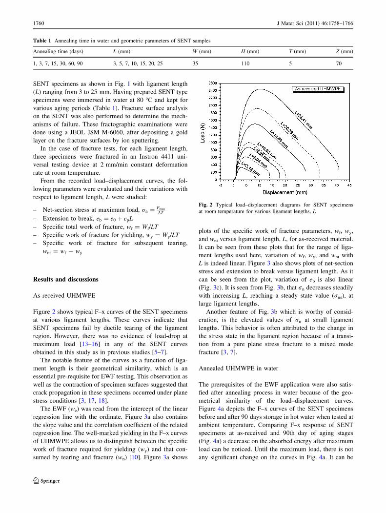
Figure 2 shows typical F–x curves of the SENT specimens
at various ligament lengths. These curves indicate that
SENT specimens fail by ductile tearing of the ligament
region. However, there was no evidence of load-drop at
maximum load [13–16] in any of the SENT curves
obtained in this study as in previous studies [5–7].
The notable feature of the curves as a function of liga-
ment length is their geometrical similarity, which is an
essential pre-requisite for EWF testing. This observation as
well as the contraction of specimen surfaces suggested that
crack propagation in these specimens occurred under plane
stress conditions [3, 17, 18].
The EWF (we) was read from the intercept of the linear
regression line with the ordinate. Figure 3a also contains
the slope value and the correlation coefficient of the related
regression line. The well-marked yielding in the F–x curves
of UHMWPE allows us to distinguish between the specific
work of fracture required for yielding (wy) and that con-
sumed by tearing and fracture (wn) [10]. Figure 3a shows
plots of the specific work of fracture parameters, wf, wy,
and wnt versus ligament length, L, for as-received material.
It can be seen from these plots that for the range of liga-
ment lengths used here, variation of wf, wy, and wnt with
L is indeed linear. Figure 3 also shows plots of net-section
stress and extension to break versus ligament length. As it
can be seen from the plot, variation of eb is also linear
(Fig. 3c). It is seen from Fig. 3b, that rn decreases steadily
with increasing L, reaching a steady state value (rns), at
large ligament lengths.
Another feature of Fig. 3b which is worthy of consid-
eration, is the elevated values of rn at small ligament
lengths. This behavior is often attributed to the change in
the stress state in the ligament region because of a transi-
tion from a pure plane stress fracture to a mixed mode
fracture [3, 7].
Annealed UHMWPE in water
The prerequisites of the EWF application were also satis-
fied after annealing process in water because of the geo-
metrical similarity of the load–displacement curves.
Figure 4a depicts the F–x curves of the SENT specimens
before and after 90 days storage in hot water when tested at
ambient temperature. Comparing F–x response of SENT
specimens at as-received and 90th day of aging stages
(Fig. 4a) a decrease on the absorbed energy after maximum
load can be noticed. Until the maximum load, there is not
any significant change on the curves in Fig. 4a. It can be
Table 1 Annealing time in water and geometric parameters of SENT samples
Annealing time (days) L (mm) W (mm) H (mm) T (mm) Z (mm)
1, 3, 7, 15, 30, 60, 90 3, 5, 7, 10, 15, 20, 25 35 110 5 70
Fig. 2 Typical load–displacement diagrams for SENT specimens
at room temperature for various ligament lengths, L
1760 J Mater Sci (2011) 46:1758–1766
123

deduced from the curves that annealing process in water
especially affected the work of plastic deformation. It can
be seen from Fig. 4a that there is no load-drop at maximum
load both for as-received material and 90th day material.
So it cannot be confirmed if ligament region was fully
yielded at maximum load. Nevertheless attention was paid
to the maximum load registered on the load displacement
curves [3, 7].
Figure 4b shows plots of the specific work of fracture
parameters, wf, wy, and wnt versus ligament length, L, for
90th day material. Variation of wf, wy, and wnt with L is
also linear as in as-received material but there is a signif-
icant difference between as-received material and 90th day
material on EWF parameters (Table 2) due to annealing
process.
To understand the effect of annealing process in water
on the variation of net-section stress (rn) with ligament
length (L), the plots of rn–L is given in Fig. 4c for
as-received and for 90th day material. The prominent
attribute of the figure is the variation of net-section stress
with ligament length for 90th day material; there is not an
elevation on the values of rn at small ligament lengths
because of the annealing effect. The crack tip plastic
deformation zone of the annealed material did not enhance
enough to disturbed by the lateral boundaries of the spec-
imen and as a result of this the values of rn did not increase
at small ligament lengths. In other words the state of the
stress for 90 days annealed material in water is always pure
plane stress. The net-section stress of annealed material for
all ligament lengths is approximately equal yielding
strength (&ry-90 = 23.3 MPa).
The effect of annealing process in water on extension to
break can be found in Fig. 4d. The extrapolated value
(crack opening displacement value), e0 is regressed from
6.94 to 5.30 mm for 90th day of annealing process in
water. The variation of extension to break with liga-
ment length is fairly linear for annealed material as in
as-received material.
Figure 5 shows crack tip plastic deformation zone for
as-received and 90th day samples. Notable feature of this
figure is the shape and size of plastic deformation zones;
for as-received samples size of the plastic deformation
Fig. 3 a Specific work of fracture parameters versus ligament length, L, b net-section stress, rn and c extension to break, eb, versus ligament
length for as-received material
J Mater Sci (2011) 46:1758–1766 1761
123

zone is increasing with increasing ligament length while
the shape is almost same (geometrically similar) but for
90th day samples size of the plastic deformation zone is
also increasing with increasing L but the shape of it is not
similar for all ligament lengths because of the annealing
effect.
From Fig. 6a and b, specific essential and plastic work
terms were determined according to Eqs. 5 and 6. The
related specific essential and plastic data are depicted as a
function of the annealing time in Fig. 6c and d. One can
notice that from the 60th day of the process annealing in
water strongly reduces the specific EWF parameters. On
the other hand, the effect of annealing process is less
pronounced for the specific plastic work terms (Fig. 6c, d).
Plastic work was influenced by the water uptake and the
water worked as plasticizer in UHMWPE [2].
Effect of annealing time in water
To understand the effect of annealing time on the fracture
response of UHMWPE via examining the variations of
thermal characteristics (degree of crystallinity and melting
temperature), A Mettler Toledo DSC1 (differential scan-
ning calorimetry) was used to measure the heat of fusion of
Fig. 4 a Comparison of the force–elongation curves of as-received
and 90 days annealed SENT specimens for various ligament lengths.
b Specific work of fracture parameters versus ligament length, L.
c Net-section stress, rn, d extension to break, eb, versus ligament
length for as-received and 90 days annealed material
Table 2 Work of fracture parameters for as-received and 90th day UHMWPE samples
Annealing period EWF parameters
we (kJ/m2) bwp (MJ/m3) we,y (kJ/m2) bywp,y (MJ/m3) we,nt (kJ/m2) bntwp,nt (MJ/m3)
As-received 146.12 16.12 48.52 4.24 97.60 11.88
90th day 89.41 14.98 30.67 5.02 58.74 9.96
1762 J Mater Sci (2011) 46:1758–1766
123

the UHMWPE under nitrogen atmosphere. For this purpose
the DSC analysis for 0, 15, 30, 60 and 90th days of
annealing process in water was carried out between 30 and
350 �C at a heating rate of 10 �C/min. 10–12 mg speci-
mens were cut from each heat treated plaque for DSC
analysis. Three specimens were tested for each type of
treated samples.
The relative degree of crystallinity (percent improve-
ment in crystallinity compared to as-received sample) (g%)
values were obtained from Eq. 1 in order to understand the
effect of annealing time in water.
g ¼ ðDHf;i � DHf;0Þ=DHf;0 � 100% ð9Þ
where DHf,0 and DHf,i are the heat of fusion of as-received
sample and the heat of fusion of sample after the annealing,
respectively [19, 20].
As it can be seen from Fig. 6e and Table 3 there is not
any notable change on the crystallinity of the samples till
60th day of the annealing process in water. In the other
words annealing process does not affect the material before
60th day. The annealing effect shows itself on F–x curves
of both L = 5 mm and L = 20 mm samples (see Fig. 6a,
b). From Fig. 6a and b, there is a significant change on the
absorbed energy under the area of F–x curves for 60th and
90th day samples both L = 5 mm and L = 20 mm. 90-20-
01 coded sample refers to UHMWPE which is annealed in
water for 90 days with ligament length of 20 mm.
SEM images of the fracture surfaces given in Figs. 7 and
8 show the striking effect of the annealing process in water
on the fracture response of the material. Fracture surfaces
look exactly similar for as-received, 15th day and 30th day
samples but after 30th day a remarkable change showed up
itself on the fracture surface; a transition from a ductile
fracture to a mixed fracture. This transition caused by water
uptake of material during annealing process in water. As a
result of this transition, EWF parameters as shown in Fig. 6c
and d reduced from the 60th day of the annealing process.
Figure 9 shows the effect of annealing process in water
on the plastic deformation zone. From this figure it can be
seen that there is not any change on the size and shape of
the plastic deformation zone till 60th day of annealing
process for both L = 5 and L = 20 mm. This result is
parallel to water uptake graphic in Fig. 6e.
Conclusions
The fracture properties of UHMWPE before and after
annealing process in water were measured by EWF method
as a function of annealing time. From the results presented
in this study the following conclusions were drawn:
1. As a result of specimen geometry (SENT) there was no
evidence of load-drop at maximum load in any of the
F–x curves obtained in this study. UHMWPE did not
Fig. 5 Plastic deformation zones of a as-received and b 90 days annealed in water samples for various ligament lengths
J Mater Sci (2011) 46:1758–1766 1763
123

indicate full ligament yielding before the plastic prop-
agation; the EWF method was successfully applied,
showing that this requirement does not seem mandatory.
2. The results, obtained from water uptake graphic, EWF
plots and fracture surfaces show that EWF method was
used properly for UHMWPE before and after anneal-
ing process in water.
3. Annealing process in water showed up itself nei-
ther fracture surfaces nor EWF parameters until 60th
day.
Fig. 6 a Load–displacement curves for L = 5 mm samples as a
function of annealing time. b Load–displacement curves for
L = 20 mm samples as a function of annealing time. c Specific
essential work of fracture, we and its yielding, we,y and necking-
tearing we,nt related terms as a function of annealing time for the
annealed UHMWPE. d Specific plastic work of fracture, wp and its
yielding, wp,y and necking-tearing wp,nt related terms as a function of
annealing time for the annealed UHMWPE. e Influence of annealing
time on the crystallization of UHMWPE
1764 J Mater Sci (2011) 46:1758–1766
123

4. Maximum net-section stress elevated at small ligament
lengths for as-received material but it did not raise at
small ligament lengths for 90th day samples because
water acts as plasticizer in material finally plastic
deformation zone did not disturbed by lateral boundary
of the sample for 90th day samples.
5. The specific EWF terms was more sensitive for the
annealing time than the plastic ones.
6. Specific EWF term regressed from (we) 146.12 to
89.41 kJ/m2 due to annealing effect.
Table 3 Relative crystallinity (percent improvement in crystallinity
compared to as-received sample) indicators as implied from heat of
melting for various annealing times in water
Sample code DH (J g-1) g (%)
0-20-01 (as-received) 150.68 0
15-20-01 152.45 1.17
30-20-01 152.69 1.34
60-20-01 157.65 4.62
90-20-01 157.45 4.50
Fig. 7 Effect of annealing time
in water on the fracture surface
Fig. 8 SEM micrographs of the fracture surfaces of the 60th day and 90th day samples
J Mater Sci (2011) 46:1758–1766 1765
123

References
1. Broberg KB (1968) Int J Fract 4:11
2. Barany T, Karger-Kocsis J, Czigany T (2003) Polym Degrad Stab
82:271
3. Arkhireyeva A, Hashemi S (2001) Polymer 43:289
4. Mouzakis DE, Stricker F, Mulhaupt R, Karger-Kocsis J (1998)
J Mater Sci 33:2551. doi:10.1023/A:1004345017105
5. Hashemi S (2003) J Mater Sci 38:3055. doi:10.1023/A:
1024752508458
6. Mai YW, Cotterell B (1986) Int J Fract 32:105
7. Arkhireyeva A, Hashemi S, O’brien M (1999) J Mater Sci
34:5961. doi:10.1023/A:1004776627389
8. Arkhireyeva A, Hashemi S (2002) J Mater Sci 37:3675.
doi:10.1023/A:1016561225281
9. Barany T, Ronkay F, Karger-Kocsis J, Czigany T (2005) Int J
Fract 135:251
10. Karger-Kocsis J (1996) Polym Bull 37:119
11. Yang W, Xie BH, Shi W, Zuo M, Li ZM, Yang MB (2005)
J Mater Sci 40:5323. doi:10.1007/s10853-005-4398-x
12. Hashemi S (2003) Polym Test 22:589
13. Naz S, Sweeny J, Coates PD (2010) J Mater Sci 45:448.
doi:10.1007/s10853-009-3961-2
14. Chen H, Karger-Kocsis J, Wu J (2004) Polymer 45:6375
15. Barany T, Czigany T, Karger-Kocsis J (2003) Periodica Poly-
technica Ser Mech Eng 47:91
16. Karger-Kocsis J, Moskala EJ (2000) Polymer 41:6301
17. Gong G, Xie BH, Yang WY, Li ZM, Zhang WQ, Yang MB
(2005) Polym Test 24:410
18. Gong G, Xie BH, Yang W, Li ZM, Lai SM, Yang MB (2006)
Polym Test 25:98
19. Yilmaz T (2010) J Mater Sci 45:2381. doi:10.1007/s10853-
009-4204-2
20. Cao J, Chen L (2005) Polym Compos 26:713
Fig. 9 Effect of annealing time in water on the plastic deformation zone for a L = 5 mm and b L = 20 mm samples
1766 J Mater Sci (2011) 46:1758–1766
123