Embed Size (px)
Citation preview

Research ArticleEffect of Annular Gas-Liquid Two-Phase Flow on DynamicCharacteristics of Drill String
Baojin Wang Zhongyang Wang Liuci Wang and Pengyu Sun
Department of Mechanical Science and Engineering Northeast Petroleum University Daqing 163318 Heilongjiang China
Correspondence should be addressed to BaojinWang bjwangbaojin126com and ZhongyangWang wzy1719393666126com
Received 26 March 2021 Accepted 28 October 2021 Published 11 November 2021
Academic Editor Junhong Park
Copyright copy 2021 BaojinWang et al 0is is an open access article distributed under the Creative Commons Attribution Licensewhich permits unrestricted use distribution and reproduction in any medium provided the original work is properly cited
Natural gas hydrate (NGH) is a kind of new type green energy source with giant reserves which has been thought of highly byenergy explorers in the world However NGH breaks down to produce some natural gas that enters the annulus and flowstogether with the drilling fluid 0e gas-liquid two-phase flow can have an impact on the work of the drill string 0erefore it isimportant to study gas-liquid two-phase flow in the annulus on the dynamic characteristics of the drill string In this article takinga single drill string as the research object a fluid-structure coupled finite element mathematical model of two-phase flow in theannulus and drill string is established based on computational fluid dynamics and computational structural dynamics theory 0efinite element numerical simulation method is used to analyze the influence of drilling fluid and natural gas in the annulus on thedynamic characteristics of the drill string 0e simulation analysis shows the following (1) 0e motion of drilling fluid or naturalgas in the annulus will reduce the natural frequency of the drill string and the drilling fluid has a greater impact on the naturalfrequency of the drill string (2) When single-phase drilling fluid flows in the annulus the displacement peak in different di-rections maximum equivalent stress and strain of the drill string increase with the increase of the drilling fluid flow velocity orpressure and the drilling fluid pressure has a more significant effect (3)When the gas-liquid two-phase fluid flows in the annulusthe displacement peak maximum equivalent stress velocity amplitude and acceleration amplitude of the drill string all increasewith the natural gas flow velocity and natural gas content increase and the natural gas flow velocity has a more significant effect
1 Introduction
Energy plays an important role for social stability and na-tional construction In recent years there is an increasingdemand for energy in various fields which led to decreasingor even near depletion of oil and gas resources on land0erefore various countries have turned their attention tothe ocean Marine resources are very rich but it is estimatedthat the exploitation rate of marine resources is only around30 and a large amount of energy is waiting to be developed[1] In ocean resources natural gas hydrate (NGH) is a kindof new energy that has high energy density wide distri-bution cleanliness and low pollution It is predicted thatChinarsquos NGH reserves in the South China Sea exceed 10billion tons [2]
Various countries have actively participated in the NGHexploitation but there has been a situation of high input and
low output and the marine environment has been pollutedDuring the drilling process drilling engineering is a keytechnology for hydrate exploitation As shown in Figure 1the drill string is an indispensable pipe tool its workingenvironment is filled with drilling fluid and subjected tovarious loads which accelerates the fatigue failure of the drillstring When the drill string encounters NGH NGH breaksdown to produce some natural gas that enters the annulusand flows together with the drilling fluid which exacerbatesthe damage to the drill string 0erefore it is of great sig-nificance to study the influence of fluid-structure interactionon dynamic characteristics of drill string which providessafety guidance for NGH exploitation
Fluid-structure coupled theory is a discipline formed bythe combination of fluid mechanics and structural me-chanics At present the phenomenon of fluid-structureinteraction has existed in many fields and the study of fluid-
HindawiShock and VibrationVolume 2021 Article ID 9976164 13 pageshttpsdoiorg10115520219976164
structure interaction has broad application prospects Atpresent research methods are mainly focused on three as-pects theoretical research experimental analysis and nu-merical simulation Scholars have studied dynamiccharacteristics of the drilling string under fluid-structureinteraction from different angles Chang et al [3] and DavidYtrehus et al [4]investigated the effect of different types ofdrilling fluids on the vibration characteristics of the drillstring Salehi andMoradi [5] Tran et al [6] Ma et al [7] andChen et al [8] studied the effects of density flow ratefrequency and other parameters of drilling fluid on the drillstring vibration characteristics Cao et al [9] studied theinteraction between the internal fluid and the string of oiland gas wells Yang et al [10]studied the influence of drillingfluid on drill string vibration by experiments and numericalsimulation methods 0e above-mentioned scholars onlystudied the influence of the fluid inside the drill string on thedrill string ignoring the effect of fluid movement inside theannulus on the drill string Kootiani and Samsuri [11]Sayindla et al [12] and Liu and Zhang [13] analyzed theinfluence of the types and properties of drilling fluid in theannulus on pressure drop by numerical methods Yang et al[14] analyzed the effect of annulus drilling fluid on the drillstring lateral vibration by numerical simulation technologyKhajiyeva et al [15 16] established a mathematical model ofdrill string vibration and analyzed the gas velocity influencein the annulus on drill string vibration Feng et al [17]studied the influence of annulus fluid characteristics onannulus pressure to protect deep well casings 0e above-mentioned scholars analyzed the effect of gas or liquid in theannulus on the drill string but ignored the impact on the drillstring when both gas and liquid fluids are present in theannulus Kiran et al [18] Sorgun et al [19] and Zhao et al[20] analyzed the effect of gas-liquid two-phase flow in theannulus on pressure loss by experimental and numericalmethods Zhou et al [21] conducted a numerical simulationanalysis on the motion law of gas-liquid two-phase flow inthe annulus Xie et al [22] developed a mathematical modelto numerically analyze the gas-liquid two-phase flow in thewellbore 0e above-mentioned scholars studied the fluidcharacteristics of the gas-liquid two-phase flow in the an-nulus without considering the impact of the two-phase flowon the drill string
In recent years the studies on the influence of gas-liquidtwo-phase flow in the annulus on the dynamic character-istics of the drill string are rare 0erefore taking a singledrill string as the research object fluid governing equationsand structural governing equations are established based on
fluid dynamics and structural dynamics theory and the fluidand structure motion equations are derived by usingGalerkin finite element method 0e calculation results aretransferred on the interface between the fluid domain andthe structural domain to ensure that the boundary condi-tions of the coupling surface are met and then numericalsimulation methods are used to build a finite element cal-culation model and analyze the effects of two fluids in theannulus drilling fluid and natural gas on the dynamiccharacteristics of the drill string
2 Fluid-Structure Coupled Finite ElementMathematical Model
21Model Description 0e fluid in the annulus and the drillstring structure are regarded as the research object in thispaper 0e fluid in the annulus includes drilling fluid andnatural gas0erefore a fluid-structure coupledmodel of thedrill string system is established In order to study the in-fluence of gas-liquid two-phase flow on drill string dy-namics the model needs to be simplified by making thefollowing assumptions [23ndash25] (1) the drill string is a ho-mogeneous prismatic and isotropic circular pipe (2) thedrill string is coaxial with the wellbore both are annular incross section and the wellbore is considered adiabatic (3)the gas-liquid two-phase fluid is uniformly mixed and thechemical change and phase change of both are not con-sidered 0e boundary conditions at both ends of the drillstring that is parallel to the ground are fixed constraints It isassumed that the drilling fluid flow direction is thez-direction the vertical direction of the ground is they-direction and the direction perpendicular to the drillstring and parallel to the ground is the x-direction as shownin Figure 2
0e research on the interaction between the fluid in theannulus and the drill string is a typical fluid-structure in-teraction problem 0e motions of fluid and structure needto meet their respective equations and then the equations ofthe fluid domain and the structure domain are combined toderive the fluid-structure coupled equation 0e parametersat the fluid-solid coupled surface need to meet the con-servation of boundary conditions
22 FluidControlEquations 0enatural gas decomposed byNGH enters the annulus and flows together with the drillingfluid According to the amount of gas in the annulus dif-ferent gas-liquid two-phase flow patterns are formed in theannulus0ere are two states of fluid flow in the annulus thedrilling fluid flowing alone and the drilling fluid and naturalgas flowing together 0e above both types of fluids obey thelaws of physical conservation In the flow field analysisconsidering the problems of calculation accuracy and cal-culation speed the Euler-Euler multiphase flow model andthe standard k-ε turbulence model are used to solve themathematical problem of the annulus air-liquid two-phaseflow It is assumed that the two fluids are incompressible thephysical parameters of the two fluids are constant and the
drilling fluid debris gas hydrate drill string bit
Figure 1 Working environment of the drill string
2 Shock and Vibration
heat transfer between them is not considered 0erefore thecontrol equations of the two fluids are shown as follows [26]
Continuity equation of the gas phase
z ρgα1113872 1113873
zt+
z ρgαvg1113872 1113873
zx 0 (1)
Continuity equation of the liquid phase
z ρl(1 minus α)1113858 1113859
zt+
z ρl(1 minus α)vl1113858 1113859
zx 0 (2)
Mixed momentum equation
z
ztρgαvg + ρl(1 minus α)vl1113960 1113961 +
z
zxρgαv
2g + ρl(1 minus α)v
2l1113960 1113961
+zp
zx+ f + ρgα + ρl(1 minus α)1113960 1113961 middot g 0
(3)
0e equations for the other two directions can be ob-tained in the same way and are not described here
Gas-liquid mixing density equation
ρ ρgα + ρl(1 minus α) (4)
0e fluid in this paper is turbulent and the standard k-εturbulence model is applied 0is model has been applied tomost engineering problems and has good convergence 0econstraint equations are as follows
z(ρk)
zt+ nabla(ρvk) nabla μ +
μt
σk
1113888 1113889nablak1113890 1113891 + Pk minus ρε
z(ρε)zt
+ nabla(ρvε) nabla μ +μt
σε1113888 1113889nablaε1113890 1113891 +
εk
Cε1Pk minus Cε2ρε( 1113857
μt Cμρk2
ε
(5)
0e above-mentioned continuity equations momentumequations and turbulence equations form the controlequations for gas-liquid two-phase flow 0e controlequation of gas-liquid two-phase flow is discretized byGalerkin finite element method to obtain the fluid motionequation 0e pressure values of the fluid on different po-sitions of the outer wall of drill string can be obtained bysolving the motion equation above which provides fluidpressure and other data for the subsequent fluid-structureinteraction analysis
23 Structural Control Equations 0e structural vibrationequation is the basis for deriving the structural motionequation 0e vibration equation of the drill string isestablished according to Hamiltonrsquos principle [27 28]which is as follows
1113946t2
t1
δ(T minus V)dt + 1113946t2
t1
δWdt 0 (6)
Both ends of the drill string with the length of L are fixedconstraints 0e kinetic energy of the drill string is expressedas follows
T 1113946L
0
12
mzy
zt1113888 1113889
2
dz (7)
0e potential energy of the drill string system mainlyincludes the following two parts
Potential energy Vb generated by the bending of the drillstring
Vb 1113946L
0
12EI
z2y
zz21113888 1113889
2
dz (8)
Potential energy change Vo generated by annular fluidpressure
Vo 1113946L
0
12PA
zy
zz1113888 1113889
2
dz (9)
0erefore potential energy of drill string system isobtained as follows
V 1113946L
0
12EI
z2y
zz21113888 1113889
2
dz + 1113946L
0
12PA
zy
zz1113888 1113889
2
dz (10)
0e forces subjected by the drill stringmainly include thedamping force and the additional lateral force of the annulusfluid 0e additional lateral force of the annulus fluid isexpressed as follows [28]
Fl CMmo
zy
zt+ v
zy
zz1113888 1113889
2
(11)
where CM is the additional mass factor whichmainly reflectsthe effect of the diameter size of annular fluid domain on Fl
CM D
2+ d
2o
D2
minus d2o
(12)
0erefore the virtual work done by forces on the drillstring is expressed as follows
δW 1113946L
0F minus Fl minus c
zy
zt1113888 1113889δydz (13)
0e boundary conditions of the drill string with fixedconstraints at both ends are expressed as follows
y(0) y(L) yprime(0) yprime(L) 0 (14)
Fixed supporty
z
Figure 2 A simplified model of the drill string system
Shock and Vibration 3
Substituting (7) (10) and (13) into (6) considering theboundary conditions and using integral by parts the fol-lowing equation is obtained
1113946t2
t1
1113946L
0m + CMmo( 1113857
z2y
zt2 + CMmov
2+ PA1113872 1113873
z2y
zz2 + 2CMmov
z2y
zzzt+ EI
z4y
zz4 + c
zy
ztminus F1113890 1113891δydzdt (15)
0erefore after simplification process the vibrationdifferential equation of the drill string is expressed as follows
EIz4y
zz4 + CMmov
2+ PA1113872 1113873
z2y
zz2 + c
zy
zz+ m + CMmo( 1113857
z2y
zt2
+ 2CMmovz2y
zzzt F
(16)
0e basis for the study of structural dynamics propertiesis the structural equations of motion 0e Hermite inter-polation function and the Galerkin finite element methodare used to discretize the vibration differential equation andfinally the motion equation of the structural unit is obtained[27]
Meeurode + Ce
_de + Kede Ge (17)
where Me Ce and Ke are the mass damping and stiffmatrices of the drill string unit de and Ge are the dis-placement and load at the node of the drill string unit
0e motion equation of structural units is transformedinto the motion equation of the whole structure by way ofcombination
M eurod + C _d + Kd G (18)
where M C and K are composed of corresponding elementmatrices and d and G are the total displacement and totalload of the drill string
24 Fluid-Structure CoupledMotion Equation According tothe governing equations of fluid and structure the finiteelement method is employed to solve the fluid-structureinteraction dynamics problem
Based on the continuity equations momentum equa-tions and turbulence equations of the fluid the Galerkinfinite element method is used to discretize the aboveequations to obtain the motion equation of the fluid element[29 30]
HePe + Fe_Pe + Ee
euroPe Fa (19)
where He Fe and Ee are stiff damping and mass matrices offluid element
0e motion equation of fluid units is transformed intothe motion equation of the whole flow field by way ofcombination
HP + F _P + E euroP Fa (20)
whereH F E and B are composed of corresponding elementmatrices
When the drill string is in contact with the annulus fluidthere is an interaction between fluid and drill string on thecontact surface where Fa is the load of the drill string on thefluid [31]
Fa minusρBeurod (21)
Substituting equation (21) into equation (20) the fol-lowing equation is obtained [32]
HP + F _P + EeuroP + ρBeurod 0 (22)
Considering the fluid-structure interaction problem Gin equation (18) includes the load F0 of the annulus fluid onthe drill string and other loads F1 0erefore equation (18) istransformed into
M eurod + C _d + Kd + F0 + F1 0 (23)
where [31]
F0 minusBTP (24)
Substituting equation (24) into (23) the followingequation is obtained [30]
M eurod + C _d + Kd minus BTP + F1 0 (25)
0e essence of the fluid-structure interaction problem isto solve equation (22) and (25) and the coupled equation isas follows
E ρaB
0 M1113890 1113891
P
d⎡⎢⎣ ⎤⎥⎦ +
F 0
0 C1113890 1113891
P
d⎡⎢⎣ ⎤⎥⎦ +
H 0
minusBT
K1113890 1113891
P
d1113890 1113891 +
q
F11113890 1113891 0
(26)
0e above equation shows that the unknown quantitiesinclude drill string displacement and fluid pressure 0eparameters of drill string displacement and fluid pressure areobtained by solving the above equation and transferred toeach other on the coupling surface for fluid-structure in-teraction dynamics study
25 Data Transfer between Fluid-Structure CouplingInterfaces When analyzing fluid-structure interactionproblem the key is the information transfer between fluid-structure coupling interfaces 0ere are 2 types of fluid-solidinteraction one is that the coupling effect only occurring at
4 Shock and Vibration
the contact surface between fluid and structure and theother is that the coupling effect occurs at the overlap betweenfluid and structure 0e coupling type in this paper belongsto the former one 0e load transfer process of the couplinginterface is shown in Figure 3
0e movement of fluid and structure on the couplinginterface needs to meet displacement and force balance
Df Ds
Tf Ts(27)
During the data transfer process between fluid-structurecoupling interfaces the pressure on the inner surface of theannulus fluid needs to be transferred to the outer surface ofthe drill string 0e transfer equation is as follows
τs H1τf (28)
And then the drill string is deformed under annulus fluidpressure which will be fed back to the fluid through thefollowing equation
df H2ds (29)
0e data transfer between fluid and structure on theinterface is realized through the above displacement andstress equations and then the fluid-structure coupling dy-namics problem is studied
0e partitioned coupling method is used by the solutionof the fluid-structure interaction 0e fluid domain equationand the structure domain equation are solved by the abovemethod and the calculation results of the fluid domain andthe structure domain are exchanged through the couplingsurface 0e analysis steps of the partitioned couplingmethod are as follows
(1) Assign initial boundary conditions such as inletvelocity and outlet pressure of the two-phase fluid inthe annulus
(2) Solve the fluid domain and get the fluid pressure(3) Transfer the fluid pressure load to the structure
through the coupling surface and solve the structuraldomain to obtain the structural displacement
(4) Transfer the structural displacement to the fluidthrough the coupling surface to get the deformationof the fluid domain and then recalculate the fluiddomain to update the fluid pressure
(5) According to the above calculation steps keep re-peating the calculation until the fluid pressure loadand structural displacement meet the calculationerror
3 Numerical Simulation and Analysis
0e finite element calculation model is established as shownin Figure 4 0e model includes structure domain and fluiddomain 0e inlet boundary of the annulus fluid domain isdefined as the velocity inlet the outlet boundary of theannulus fluid domain is defined as the pressure outlet andthe outer surface of the drill string and the inner surface of
the fluid domain are defined as the coupling surfaces Asingle drill string is selected as the structural model and thefluid in the annulus includes drilling fluid and natural gas0e structure and fluid main parameters are listed in Table 1and other fluid parameters and specific parameters of theboundary conditions are determined according to specificworking conditions
0e numerical simulation analysis involves the couplingproblem of fluid and solid so it is necessary to mesh the fluiddomain and the structural domain 0e grid number affectsthe final result of numerical simulation so different gridnumbers are selected for grid independence test in thispaper When the drilling fluid flow rate is 4ms the meshindependence of the numerical model is verified by takingthe maximum equivalent stress of the drill string as theevaluation index [33]
As shown in Table 2 as the grid number increases themaximum equivalent stress of the drill string gradually tendsto converge By comparing the change trend of the result themesh number of 256845 is selected for subsequent numericalcalculation If the grid number continues to increase on thebasis the effect on the calculation result is relatively smallie grid independence has been satisfied [34]
0e selection of time step size will also affect the cal-culation result Taking the abovemesh number 256845 as themesh model 01 s 005 s 001 s 0005 s and 0001 s are se-lected for time-independent test 0e results show that thechange trend of the results obtained from the time step test issimilar to that from the grid number test and both graduallyconverge 0erefore based on comprehensive considerationof computing resource and accuracy the calculation timestep in this paper is 0005 s
31Modal Analysis of Drill String under Fluid-Solid CouplingModal analysis is the basis for studying the structural dy-namic characteristics 0e modal analysis helps researchersknow the structural modal parameters provides a reliablebasis for the analysis of the structural dynamic character-istics and prevents the structure from resonating
annularfluid
domain
fluid pressure
data updating
structural displacement
structuraldomain
Figure 3 Data transfer diagram between fluid and structure
annulus oulet annulus inletflow field drill string
Figure 4 Finite element calculation model
Shock and Vibration 5
It can be known from the statement in Section 22 thatthere are two states of fluid flow in the annulus the drillingfluid flowing alone and the drilling fluid and natural gasflowing together 0erefore in order to analyze the effect offluid-structure interaction on the modal characteristics ofdrill string numerical simulations are performed for modalproblems under three cases of no coupling liquid-solidcoupling and gas-liquid-solid coupling respectively Asshown in Table 3 the first six orders natural frequencies areextracted separately for discussion and analysis
0e modal analysis results include the natural frequencyand mode shape of the structure Firstly the natural fre-quency of the drill string is analyzed under the above threecases As shown in Table 3 the adjacent two-order fre-quencies are almost equal due to the constraint and shapesymmetry of the drill string structure From Table 3 thenatural frequency of the drill string under liquid-solidcoupling is lower than that under no coupling 0e reason isthat the movement of the drilling fluid in the annulus createspressure on the outer wall of the drill string which causes themass of the drill string to increase and subsequently thenatural frequency to decrease As the modal order numberincreases the difference rate between the natural frequenciesof the drill string under the above two coupling actionsgradually decreases indicating that the effect of drilling fluidon low-order natural frequencies is greater than that of high-order natural frequencies Drilling fluid motion is aggra-vated by the vibration of the drill string under higher-ordermodes which makes the drill string vibrate more violentlyand subsequently makes the frequency of the drill stringvibration increase 0erefore as the modal order numberincreases the difference between the natural frequenciesunder liquid-solid coupling and no coupling gradually de-creases 0e natural frequency of drill string under gas-liquid-solid coupling is less than that under no coupling butmore than that under liquid-solid coupling 0e gas-phasenatural gas entering the annulus replaces part of the liquid-phase drilling fluid and the density of natural gas is muchless than that of drilling fluid So compared with the actionof drilling fluid the action of natural gas exerts less pressure
on the outer wall surface of the drill string and adds less massto the drill string with a consequent reduction in the overallcoupling effect on the drill string after gas-liquid mixing0erefore the natural frequency under gas-liquid-solidcoupling is between the natural frequency of the drill stringunder no coupling and liquid-solid coupling As the modalorder number increases the difference between the naturalfrequencies under gas-liquid-solid coupling and liquid-solidcoupling gradually increases It suggests that natural gas hasa greater impact on the higher-order natural frequenciesthan the lower-order natural frequencies and the reason isthe same as the analysis of drilling fluid factor above
0e mode shapes of the above three cases are comparedand analyzed after numerical simulation 0e mode shapesof the drill string structure are not affected by the fluid-solidcoupling but there is a tiny increase in the mode shapeamplitude due to the fluid-solid coupling 0erefore themode shape without coupling is extracted for discussion andanalysis Due to the symmetry of the drill string structurethe 1st 3rd and 5th order modes vibrate in the Y-Z planewhile the 2nd 4th and 6th order modes vibrate in the X-Zplane 0e mode shapes on the two planes are the same butthe vibration directions are perpendicular to each other0erefore the 1st 3rd and 5th order mode shapes in the Y-Zplane are extracted and normalized as shown in Figure 5According to Figure 5 the mode shape of the drill stringstructure is dominated by bending vibration and as themodal order increases there are more and more bendingparts 0e 1st order mode shape has one curved part the 3rdorder mode shape has two curved parts and the 5th ordermode shape has three curved parts As the modal ordernumber increases the natural frequency of the drill stringincreases which causes the drill string to vibrate more in-tensely and makes mode shape more complex so thenumber of bending areas also increases
0e above discussion about natural frequencies andmode shapes is further analyzed 0e action of differentfluids will all cause the natural frequency of the drill stringstructure to decrease but the vibration amplitude to slightlyincrease 0e reason is that the movement of different fluids
Table 1 Fluid and structure parameters
Parameter names Value
Structure parameter
Density (kgm3) 7850Length (m) 9
Outer diameter (mm) 115Wall thickness (mm) 8Elastic modulus (GPa) 210
Poissonrsquos ratio 03
Fluid parameter
Drilling fluid density (kgm3) 1200Drilling fluid viscosity (Pamiddots) 0001Natural gas density (kgm3) 075Natural gas viscosity (Pamiddots) 115times10minus5
Table 2 Grid independence verification
0e total number of elements 108354 151864 201034 256845 305983Maximum equivalent stress 041585 042256 042598 042687 042691
6 Shock and Vibration
exerts a force on the outer wall of the drill string subse-quently increasing the additional mass of drill string Sowhen the density viscosity velocity and other physicalparameters of the drilling fluid or natural gas change thepressure on the outer wall of the drill string and the ad-ditional mass of drill string are also altered resulting in achange in the natural frequency and amplitude of the drillstring structure
32 Influence of Drilling Fluid in the Annulus on Drill StringDynamic Characteristics When the drill string is not incontact with NGH only the drilling fluid flows in the an-nulus In different environments the drilling fluid flowvelocity and pressure are variable which has different de-grees of influence on the drill string dynamic characteristics0erefore the numerical simulation is used to analyze thechange law of some drill string dynamic characteristics withdrilling fluid flow velocity and pressure
0e effect of drilling fluid velocity on the displacementpeak of the drill string is first analyzed as shown in Figure 60e peak combined displacement and Y-direction dis-placement peak are much larger than the displacement peaksin the other two directions and curves of the peak combineddisplacement and Y-direction displacement peak withdrilling fluid flow velocity almost coincide 0e above
analysis shows that the vibration direction of drill string ismainly the Y-direction and the vibration in the other twodirections has little effect on the drill string and can even beignored As shown on the upper left corner of Figure 6 theX-direction and Z-direction displacement peak curves areenlarged to facilitate clear comparison From Figure 6 as thevelocity increases the displacement peak and its increasingrate in different directions also increase 0e above analysisshows that the greater the drilling fluid velocity the greaterthe impact on the displacement peak of the drill string andthe larger the impact on the Y-direction displacement peakamong the three directions 0e difference between theX-direction and Z-direction displacement peaks increaseswith increasing velocity indicating that the velocity factorhas a greater influence on the displacement peak in theZ-direction than in the X-direction
As shown in Figure 7 the displacement peak in differentdirections increases almost linearly as the pressure increasesBut from Figure 6 it can be found that the displacementpeak in different directions increases almost nonlinearly asthe pressure increases and a comparison of the data inFigures 6 and 7 shows that the displacement peak under theinfluence of drilling fluid pressure is greater than that under
Table 3 0e natural frequency of the drilling string under fluid-structure coupling
OrderNatural frequency (Hz) Change rate
Uncoupled Fluid-solid coupling Gas-liquid-solid coupling Former two () Later two ()1 8904 8026 8028 986 0022 8905 8026 8028 987 0023 24471 23659 23668 332 0044 24471 23658 23667 332 0045 47783 46986 47008 167 0056 47783 46987 47009 167 005
1
1
ndash10 1 2 3 4 5
Z (m)6 7 8 9
norm
aliz
atio
n pr
oces
sing
original locationThe first mode
The third modeThe fifth mode
Figure 5 Different mode shapes of drill string without coupling
000
1 2 3 4 5 6velocity (ms)
7 8
005
010
015
disp
lace
men
t (m
m)
Y-direction displacement peakZ-direction displacement peak
Peak combined displacementX-direction displacement peak
Figure 6 Variation curve of displacement peak in different di-rections with drilling fluid velocity
Shock and Vibration 7
the influence of drilling fluid velocity 0e above analysisshows that the pressure factor has a greater influence on thedrill string displacement peak than the velocity factor Whenconsidering the material strength it is necessary to focus onthe effect of drilling fluid pressure on the drill string
Figures 8 and 9 show the effects of velocity and pressure ofdrilling fluid on the maximum equivalent stress and strain ofdrill string Comparing Figures 6 and 7with Figures 8 and 9 itis found that the curves in Figures 6 and 8 present anonlinear change and the curves in Figures 7 and 9 presenta linear change It shows that under the influence ofpressure or speed the curve change trend of stress andstrain is related to the curve change trend of displacementBoth ends of the drill string are fixed constraints and otherparts are not restricted 0erefore when the drill stringdeforms the maximum equivalent stress and strain of thedrill string occur at both ends of the drill string and themaximum equivalent stress and strain of the drill string willincrease as the deformation of the drill string increases 0eabove analysis results are consistent with the curve changelaw of the above four graphs
33 Influence of Natural Gas in the Annulus on Drill StringDynamic Characteristics NGH breaks down to producesome natural gas that enters the annulus and flows togetherwith the drilling fluid 0e drill string dynamic character-istics will be affected by the natural gas flow velocity and thenatural gas volume in the annulus 0erefore the effects ofnatural gas flow velocity and gas volume fraction in annulardrilling fluid on the drill string dynamic characteristicsincluding the maximum deformation maximum equivalentstress vibration velocity and vibration acceleration aresimulated numerically
331 Influence of Natural Gas Flow Velocity on Drill StringDynamic Characteristics First the drilling fluid flow ve-locity is controlled to 2ms and the volume ratio of drillingfluid to natural gas is controlled to 9 1 by control variablemethod and then the influence of different flow rates ofnatural gas on the dynamics of the drill string is studied 0evariation law of peak combined displacement andmaximumequivalent stress of the drill string with natural gas flowvelocity is expressed in Figure 10 As shown in Figure 10both drill string peak combined displacement andmaximumequivalent stress increase with increasing natural gas flowvelocity and the increasing rate of both increases 0e aboveanalysis shows that the greater the flow velocity of naturalgas the greater the impact on drill string displacement andequivalent stress A comparison of Figure 10 with Figures 6and 8 shows that the gas flow velocity has a greater effect on
1
0
1
2
3
2 3 4pressure (MPa)
5 6
disp
lace
men
t (m
m)
Y-direction displacement peakZ-direction displacement peak
Peak combined displacementX-direction displacement peak
Figure 7 Variation curve of displacement peak in different di-rections with drilling fluid pressure
000
2
4
6
8
10
1 2 3 4 5velocity (ms)
6 7 8
05
10
15
max
imum
equi
vale
nt st
ress
(MPa
)
max
imum
equi
vale
nt st
rain
(10ndash6
)
maximum equivalent stressmaximum equivalent strain
Figure 8 Variation curve of maximum equivalent stress and strainwith drilling fluid velocity
12
10
2
4
6
8
25
20
15
10
5
0
pressure (MPa)1 2 3 4 5 6
max
imum
equi
vale
nt st
ress
(MPa
)
max
imum
equi
vale
nt st
rain
(10ndash5
)
maximum equivalent stressmaximum equivalent strain
Figure 9 Variation curve of maximum equivalent stress and strainwith drilling fluid pressure
8 Shock and Vibration
the drill string dynamic characteristics than the drilling fluidflow velocity Analysis of the reasons for this shows that asthe flow velocity of natural gas in the annulus increases thefluid motion in the annulus becomes more intense resultingin greater fluid forces on the outer wall surface of the drillstring so the deformation increases and the equivalent forceincreases
Figure 11 shows the variation law of the velocity am-plitude of drill string in the three directions with the naturalgas flow velocity From Figure 11 as the gas velocity in-creases the velocity amplitude in the Y-direction is muchgreater than that in the Z-direction and X-direction withvelocity amplitude in the Z-direction being slightly greaterthan that in the X-direction 0e above analysis shows thatthe drill string vibrates most violently in the Y direction0eresults of the simulations at both ends of the velocity am-plitude curves in three directions in Figure 11 are extractedand compared0e increasing rate of the data at both ends ofthe X-direction velocity amplitude curve is 429 0e in-creasing rate of the data at both ends of the Y-directionvelocity amplitude curve is 122 and the increasing rate ofthe data at both ends of the Z-direction velocity amplitudecurve is 118 0e above analysis shows that the natural gasflow velocity has the greater influence on the increasing rateof the velocity amplitude in the Y-direction than that in theother two directions but the increasing rate of the velocityamplitude in the three directions always increases with theincrease of the natural gas flow velocity
Figure 12 shows variation law of drill string accelerationamplitude with natural gas velocity in different directionsAs shown in Figure 12 acceleration amplitude in theY-direction is two orders of magnitude larger than that inthe X-direction and Z-direction and acceleration ampli-tude in the X-direction is slightly larger than that in theZ-direction 0e comparative analysis of Figures 11 and 12further proves that the drill stringrsquos main vibration di-rection is the Y-direction 0e curves of acceleration
amplitude with velocity in X- and Z-directions are en-larged as shown on the lower right corner of Figure 12According to the comparison of the two magnificationcurves the X-direction acceleration amplitude increasesalmost linearly and the increasing rate is nearly un-changed However the Z-direction acceleration amplitudeincreases nonlinearly 0e increasing rate of the accelera-tion amplitude in the Z-direction increases with the in-crease of the natural gas flow velocity which is the same asthe changing trend of the acceleration amplitude in the
10
4
6
8
20
15
10
05
velocity (ms)1 2 3 4 5
disp
lace
men
t (m
m)
max
imum
equi
vale
nt st
ress
(MPa
)
12
Peak combined displacementmaximum equivalent stress
Figure 10 Variation curve of peak combined displacement andmaximum equivalent stress with natural gas velocity
0
1 2 3velocity (ms)
4 5
1
2
3
4
5
6
velo
city
ampl
itude
(ms
)
Z-direction velocity amplitude
X-direction velocity amplitudeY-direction velocity amplitude
Figure 11 Variation curve of velocity amplitude in different di-rections with natural gas velocity
0
5
10
15
20
25
30
velocity (ms)1 2 3 4 5
acce
lera
tion
ampl
itude
(ms
2 )
Z-direction acceleration amplitude
X-direction acceleration amplitudeY-direction acceleration amplitude
Figure 12 Variation curve of acceleration amplitude in differentdirections with natural gas velocity
Shock and Vibration 9
Y-direction 0e above analysis shows that gas flow velocityhas the greatest effect on Y-direction acceleration thefollowed effect on Z-direction acceleration and the leasteffect on X-direction acceleration
332 Influence of Natural Gas Volume Fraction on DrillString Dynamic Characteristics First the natural gas flowvelocity is controlled to 3ms and the drilling fluid flowvelocity is controlled to 2ms by control variable methodand then the influence of different natural gas volumefraction on the dynamics of the drill string is studied
As shown in Figure 13 the variation law of the drill stringpeak combined displacement and the maximum equivalent
stress with the natural gas volume fraction is simulated It canbe seen from Figure 13 that as the natural gas volume fractionincreases the peak combined displacement and maximumequivalent stress of drill string both increase linearly 0echange trend of the curve in Figure 13 is different from that inFigure 10 and the values on the two curves in Figure 13 areboth smaller than those on the two curves in Figure 10 0eabove analysis shows that the natural gas flow velocity has agreater influence on the displacement and stress of drill stringthan the natural gas volume fraction Analysis of the reasonsfor this shows that as the natural gas volume fraction increasesthe share of drilling fluid will correspondingly decrease whichmakes the flow energy of the two-phase flow and the additionalforces on the outer drilling wall surface decrease
02
002
04
004
06
006
08
008
10
1
2
3
4
5
010
disp
lace
men
t (m
m)
max
imum
equi
vale
nt st
ress
(MPa
)
gas fraction
Peak combined displacementmaximum equivalent stress
Figure 13 Variation curve of the peak combined displacement and maximum equivalent stress with natural gas fraction
00
002 004 006 008 010
05
10
15
20
25
gas fraction
velo
city
ampl
itude
(ms
)
Z-direction velocity amplitude
X-direction velocity amplitudeY-direction velocity amplitude
Figure 14 Variation curve of velocity amplitude in different directions with natural gas fraction
10 Shock and Vibration
Figure 14 shows the variation law of velocity amplitudein different directions with natural gas volume fraction Asshown in Figure 14 the three curves present a linear changeVelocity amplitude in the Y-direction is one order ofmagnitude larger than that in the Z-direction and velocityamplitude in the Z-direction is one order of magnitudelarger than that in the X-direction A comparative analysis ofall the data in Figure 14 and Figure 11 shows that the velocityamplitude in each direction under the action of natural gascontent is all smaller than the velocity amplitudes in thecorresponding direction under the action of natural gas flowvelocity It is again confirmed that the natural gas flowvelocity has a greater impact on the drill string dynamicsthan the natural gas volume fraction
Figure 15 shows the variation law of the drill stringacceleration amplitudes in the three directions with thenatural gas volume fraction As shown in Figure 15 the three
curves also present a linear change Comparing the data inFigure 15 with that in Figure 12 the X-directional accel-eration amplitudes are nearly the same in both figures butthe Y-directional acceleration amplitude under the naturalgas volume fraction is much smaller than that under thenatural gas flow velocity 0e above analysis shows that thenatural gas flow velocity has a much greater influence on theacceleration amplitude in the Y-direction than the naturalgas volume fraction In order to clearly observe the shape ofthe acceleration amplitude curve in the X-direction andZ-direction the two curves are redrawn as shown inFigure 16 0e curves of X-direction acceleration amplitudeand Y-direction acceleration amplitude show the samechanging trend but there are fluctuations in the Z-directionacceleration amplitude 0e gas-liquid two-phase in theannulus flow along the Z-direction (axial direction) and themovement of the fluid has basically the same effect on every
0
2
4
6
8
10
12
14
002 004 006 008 010gas fraction
acce
lera
tion
ampl
itude
(ms
2 )
Z-direction acceleration amplitude
X-direction acceleration amplitudeY-direction acceleration amplitude
Figure 15 Variation curve of acceleration amplitude in different directions with natural gas fraction
035
030
025
020
015
010
110
108
106
104
102
100002 004 006 008 010
X-di
rect
ion
acce
lera
tion
ampl
itude
(ms
2 )
Z-di
rect
ion
acce
lera
tion
ampl
itude
(ms
2 )
gas fraction
X-direction acceleration amplitudeZ-direction acceleration amplitude
Figure 16 Variation curve of X- and Z-direction acceleration amplitude with natural gas fraction
Shock and Vibration 11
position on the outer wall of the drill string However thechange of natural gas volume fraction causes the flow fieldmovement to become complicated which results in anonlinear variation of the action on each position of the drillstring in the Z-direction 0erefore there are fluctuations inthe Z-direction acceleration amplitude
4 Conclusion
In this paper a fluid-structure coupled finite elementmathematical model of two-phase flow and drill string in theannulus was established by the finite element method andthen the influence of the two-phase flow of drilling fluid andnatural gas in the annulus on the dynamic characteristics ofthe drilling column was investigated by numerical simula-tion methods 0e conclusions were shown as follows
(1) Both movement of the drilling fluid and natural gasin the annulus will reduce the drill stringrsquos naturalfrequency and increase the mode shape vibrationamplitude but the drilling fluid has a greater effecton the drill stringrsquos natural frequency than thenatural gas As the modal order number increasesthe effect of fluid-structure interaction on the drillcolumnrsquos natural frequency decreases
(2) When single-phase drilling fluid flows in the an-nulus the displacement peak in different directionsmaximum equivalent stress and strain of the drillstring increase with the increase of the drilling fluidflow velocity or pressure However drilling fluidpressure has a greater effect on the displacementpeak maximum equivalent force and strain of thedrill column than drilling fluid velocity
(3) When gas-liquid two-phase fluid flows together inthe annulus the displacement peak maximumequivalent stress velocity amplitude and accelera-tion amplitude of the drill string all increase with thenatural gas flow velocity or natural gas volumefraction increase However the above-mentioneddrill string dynamics parameters change faster underthe natural gas flow velocity And the natural gas flowvelocity has a greater impact on the displacementpeak and maximum equivalent stress of the drillstring than the flow velocity of the drilling fluid
Nomenclature
α Annular section air contentρg Natural gas density (kgm3)ρl Drilling fluid density (kgm3)ρ Gas-liquid mixture density (kgm3)vg Natural gas velocity (ms)vl Drilling fluid velocity (ms)f Fluid friction pressure drop (Pamiddotmminus1)k Turbulent kinetic energy (m2s2)ε Turbulent dissipation rateCε1 Cε2 Empirical constantσk σε Turbulent Prandtl numbersPk Turbulent product
μ Dynamic viscosityμt Turbulent viscosityCμ Empirical coefficient of k-ε modelFa Load of drill string on fluid (N)Df Fluid displacement on the coupling surface (m)Tf Fluid pressure on the coupling surface (Pa)τf Pressure after fluid domain calculation (Pa)ds Displacement of the drill string under fluid
pressure (m)T Kinetic energy of drill string systemV Potential energy of drill string systemδW Virtual workm Mass per unit length of drill string (kg)E Elastic modulus of drill string (GPa)I Moment of inertia of drill string (m4)P Annular fluid pressure (Pa)A Cross-sectional area of fluid domain (m2)mo Mass per unit length of fluid (kg)D Inner diameter of wellbore (m)do Outer diameter of drill string (m)F Outside force (N)c Damping factorδy Virtual displacement (m)B Coupling matrix on coupling planeF0 Load of fluid on drill string (N)Ds Structural displacement on the coupling surface
(m)Ts Structural stress on the coupling surface (Pa)τs Structural stress under fluid pressure (Pa)df Fluid displacement under structural deformation
(m)
Data Availability
0e data used to support the findings of this study are in-cluded within the article
Conflicts of Interest
0e authors declare that there are no conflicts of interestregarding the publication of this study
Acknowledgments
0is work was supported by the National Natural ScienceFoundation of China (Grant no 11902072) China Post-doctoral Science Foundation (Grant no 2020M670880)Heilongjiang Postdoctoral Science Foundation (Grant noLBH-Z20047) and Natural Science Foundation of NortheastPetroleum University (Grant no 2019QNL-13)
References
[1] D Zhou ldquoDistribution of worldmarine oil and gas resourcesrdquoSino-Global Energy vol 22 no 12 p 55 2017 Chinese
[2] J X He C M Zhong Y J Yao P Yan and Y L Wang ldquo0eexploration and production test of gas hydrate and its researchprogress and exploration prospect in the northern SouthChina SeardquoMarine Geology Frontiers vol 36 no 12 pp 1ndash142020 Chinese
12 Shock and Vibration
[3] X P Chang X Li L Yang and Y H Li ldquoVibration char-acteristics of the stepped drill string subjected to gas-structureinteraction and spinning motionrdquo Journal of Sound andVibration vol 450 pp 251ndash275 2019
[4] J David Ytrehus A Taghipour A Golchin A Saasen andB Prakash ldquo0e effect of different drilling fluids on me-chanical frictionrdquo Journal of Energy Resources Technologyvol 139 no 3 Article ID 34502 2017
[5] MM Salehi and HMoradi ldquoNonlinear multivariable modelingand stability analysis of vibrations in horizontal drill stringrdquoApplied Mathematical Modelling vol 71 pp 525ndash542 2019
[6] Q-T Tran K-L Nguyen L Manin et al ldquoNonlinear dy-namics of directional drilling with fluid and borehole inter-actionsrdquo Journal of Sound and Vibration vol 462 Article ID114924 2019
[7] Y H Ma D F Hong Z B Cheng Y F Cao and G X RenldquoA multibody dynamic model of the drilling system withdrilling fluidrdquo Advances in Mechanical Engineering vol 8no 7 pp 865ndash876 2016
[8] Y Chen C He X Zhou and H Yu ldquoAnalysis of factorsaffecting drilling friction and investigation of the frictionreduction tool in horizontal wells in Sichuanrdquo Advances inMechanical Engineering vol 11 no 7 Article ID168781401986296 7 pages 2019
[9] Y P Cao L Guo and Y H Dou ldquoInfluence of fluid-solidinteraction on the vibration characteristics of tubing in oiland gas wellrdquo Machinery Design amp Manufacture vol 6pp 84ndash87+91 2019 Chinese
[10] C Yang RWang L Han and Q Xue ldquoAnalysis on the lateralvibration of drill string by mass effect of drilling fluidrdquoMechanical Sciences vol 10 no 2 pp 363ndash371 2019
[11] R C Kootiani and A B Samsuri ldquoSimulation of two phaseflow of liquid-solid in the annular space in drilling operationrdquoAIP Conference Proceeding American Institute of Physicsvol 1621 no 1 pp 711ndash718 2014
[12] S Sayindla B Lund J D Ytrehus and A Saasen ldquoCFDmodeling of hydraulic behavior of oil-and water-based dril-ling fluids in laminar flowrdquo SPE Drilling and Completionvol 34 no 3 pp 207ndash215 2019
[13] Y Liu andG C Zhang ldquoNumerical simulation of large-diameterannular pressure loss in riser segment of deep-water drillingrdquoAdvanced Materials Research vol 2913 pp 510ndash516 2014
[14] C H Yang R H Wang L J Han Q L Xue and L X LildquoEffect of annulus drilling fluid on lateral vibration of drill-stringrdquo Journal of Vibration Engineering vol 22 no 1pp 197ndash208 2020
[15] L Khajiyeva A Kudaibergenov and A Kudaibergenov ldquo0eeffect of gas and fluid flows on nonlinear lateral vibrations ofrotating drill stringsrdquo Communications in Nonlinear Scienceand Numerical Simulation vol 59 pp 565ndash579 2018
[16] L A Khajiyeva and A K Kudaibergenov Modeling ofNonlinear Dynamics of Drill Strings in a Supersonic Air FlowInformation Engineering Research Institute 2015 AtlantisPress USA KAM 2015
[17] F Feng A J Xiong X L Huang and X J Mou ldquoResearch onthe law and influence of casing annulus trap fluid charac-teristics on annulus pressure in deep water wellrdquo China Pe-troleum and Chemical Standard and Quality vol 39 no 2pp 180-181 2019 Chinese
[18] R Kiran R Ahmed and S Salehi ldquoExperiments and CFDmodelling for two phase flow in a vertical annulusrdquo ChemicalEngineering Research and Design vol 153 no 5 pp 201ndash2112020
[19] M Sorgun R E Osgouei M E Ozbayoglu andA M Ozbayoglu ldquoAn experimental and numerical study oftwo-phase flow in horizontal eccentric annulirdquo EnergySources Part A Recovery Utilization and EnvironmentalEffects vol 35 no 10 pp 891ndash899 2013
[20] J Zhao S G Hu PWWang and CWu ldquoFlow characteristicsof gas-solid two-phase flow in annular pipe of gas drillingrdquoAdvanced Materials Research vol 508 pp 25ndash28 2012
[21] J Zhou H J Jia and X C Li ldquoResearch on vertical annuluscontinuous gas cutting during stopping managed pressuredrilling circulationrdquo Drilling and Production Technologyvol 38 no 2 pp 17ndash19 2015 Chinese
[22] J Y Xie B Yu Y X Zhang X Y Zhang X Z Song andG C Kan ldquoNumerical study on gas-liquid flow in thewellbore of deep wellsrdquo Journal of Engineering and Ier-mophysics vol 34 no 5 pp 883ndash887 2013 Chinese
[23] T T Ding Wellbore Multiphase Flow Analysis of CoalbedMethane Gas Drilling and Process Parameters OptimizationSouth China University of Technology Guangzhou China 2014
[24] X J Zhou and J Gong ldquoFluid-structure interaction model forgas-liquid transient flowsrdquo Mechanics in Engineering vol 5pp 17ndash20 2003
[25] T S Ma J Y Zou P Chen and H S Liu ldquoInvestigation onthe influence coupling drilling fluid and formation boundaryon acoustic wave propagation in drill stringrdquo Geomechanicsand Geophysics for Geo-Energy and Geo-Resources vol 6no 1 pp 457ndash478 2020
[26] F J Wang Computational Fluid Dynamics-Principle andApplication of CFD Software Tsinghua University PressBeijing 2004 Chinese
[27] R Ren L Z Ji D L Gao and W J Huang ldquoStudy of fluidstructure interaction vibration characteristics of casing filledand surrounded by slurryrdquo Chinese Journal of Applied Me-chanics vol 34 no 4 pp 610ndash614+809 2017
[28] T X Wu and X S Lu ldquo0e influence of the annular and theinternal drilling fluids flowing in axial on the lateral vibrationof a drill collarrdquo Journal of Vibration and Shock vol 54 no 2pp 1ndash6 1995
[29] A M Zhang and S S Dai Fluid-structure Coupling DynamicsNational Defence Industry Press Beijing 2011
[30] Z Y Pei W W Guo and C J Weng ldquoFluid-structure in-teraction vibration analysis of bulkhead stiffened plate ofhigh-speed shiprdquo Engineering Mechanics vol 20 no 2pp 159ndash162 2003
[31] D C Robert Concepts and Applications of Finite ElementAnalysis Xirsquoan Jiaotong University Press Xirsquoan China 2007Chinese
[32] C Y Lu Z M Kou J Wu and H X Zhang ldquoDynamiccharacteristics of pipes conveying fluid excited by hydraulicfluctuationrdquo Journal of Huazhong University of Science andTechnology (Nature Science Edition) vol 41 no 5 pp 17ndash222013 Chinese
[33] E Liu X Wang W Zhao Z Su and Q Chen ldquoAnalysis andresearch on pipeline vibration of a natural gas compressorstation and vibration reduction measuresrdquo Energy amp Fuelsvol 35 no 1 pp 479ndash492 2020
[34] E Liu D Li W Li et al ldquoErosion simulation and im-provement scheme of separator blowdown system --a casestudy of Changning national shale gas demonstration areardquoJournal of Natural Gas Science and Engineering vol 88Article ID 103856 2021
Shock and Vibration 13
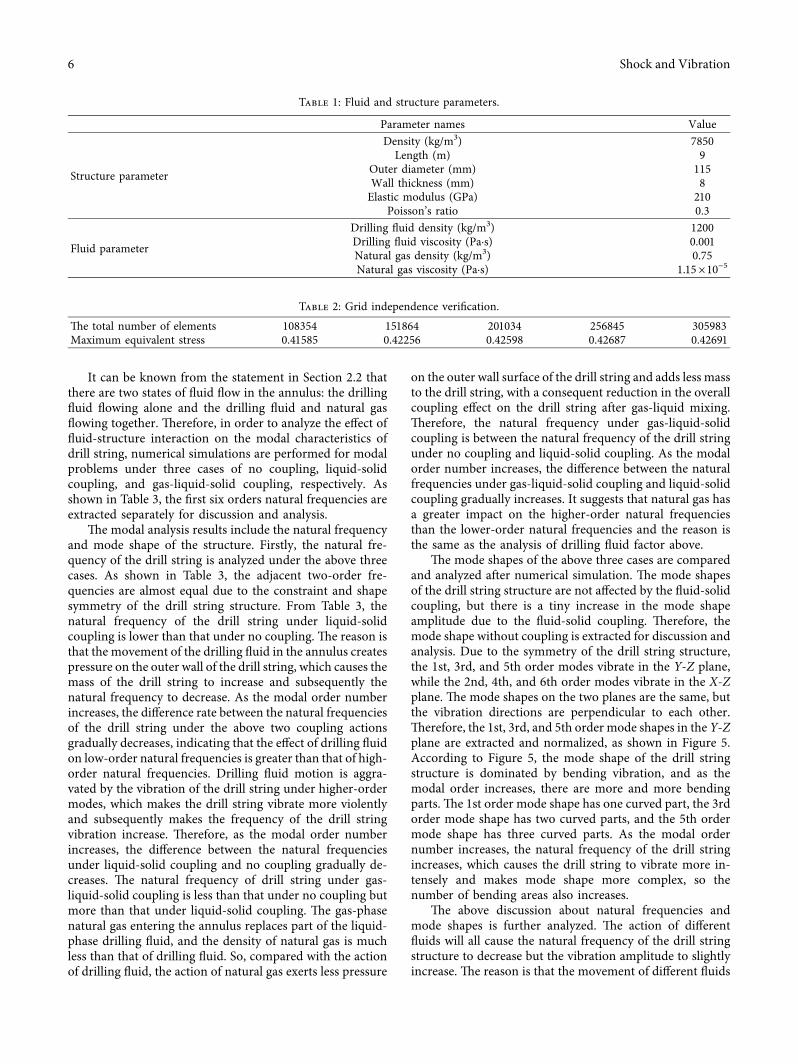