Embed Size (px)
Citation preview

E: This co not to be rel ease secur1ty reg a tJons , w rite
owing on copy issued: nR e g radnclas sifie d ltr 4/27/ 56 Dept. y(Adj. Gen . )R ef. AGAO ~
3 . 12 . 1 Secu ri I= 197 2 STUDIES OF WATER ENTRY
EFFECT OF ATMOSPHERIC PRESSURE ON ENTRY BEHAVIOR OF MODELS OF
MARK 13-6 TORPEDO WITH STANDARD HEAD (HEAD F)
AND ONE FINER HEAD (HEAD I)
REGRADED UNCLASSIFIED BY ORDER SEC. ARMY BY ~ .. ~~~-h:t-.
'fl-a-7/s-t- A~Ao-s 3 I~. I SeC. Ul'l.! fy {) · I 9 7:l.)
HYDRODYNAMICS LABORATORY
California Institute of Technoloqg
U. S. Navy Bureau of Ordnance Contract NOrd 9612
Report No.

NAVY DEPARTMENT BUREAU OF ORDNANCE CONTRACT NORD 9612
STUDIES OF WATER ENTRY
EFFECT OF ATMOSPHE RIC PRESSURE ON ENTRY BEHAVIOR OF MODELS OF
MARK 13-6 TORPEDO WITH STANDARD HEAD (HEAD F)
AND ONE FINER HEAD (HEAD r)
JANUARY 1949
BY JOSEPH LEVY
SENIOR RESEARCH ENGINEER
AND
JOHN KAYE RESEARCH ENGINEER
HYDRODYNAMICS LABORATORY CALIFORNIA INSTITUTE OF TECHNOLOGY
PASADENA, CALIFORNI\
ROBERT T. KNAPP, DIRECTOR
LABORATORY REPORT NO. N-59
COPY NO. 70

•
CONTENTS
Abstract and Conclusions
Introduction
Factors Controlling Water Entry Phenomena
General
Froude Similarity Law
Scaling of Atmospheric Pr9ssure
Scaling of Atmospheric Density .
Scaling of UnderprPssure in ll'hro t tled Cavity
Scaling of Vapor Pressure
Scaling of Viscous Forces
Scal1ng of Surface Tension
Test Conditions
Apparatus
Models .
Launching Conditions
Analysis of Data
Test Results
Head I
Head F
Reproducibility of Trajectories
Conclusion
Appendix I .. The Controlled Atmosphere Launching Tonk
The Trajectory Analyzer
Appendix I I •
Bibliography
CONFI DENTIAL
Page No
1
2
2
2
3
4
6
6
7
8
8
8
8
11
11
12
13
24
24
26
28
28
30
32
33
CONFIDENTIAL


CDN F t DENT I.Al
ABSTRACT AND CDNQUSIONS
Water entry tests of 2-inch diameter models of the MK 13-6 Torpedo with two nose shapes were !l¥)de in the Controlled Atmos}:Xlere !J:lunching Tank to determine:
a. The effect of atmos}:Xleric pressure on the-water entry behavior of S!l¥)ll models .
b. The influence of nose shape on the magnitude of atmospheric pressure effects .
c. Whether model behavior will be similar to prototype behavior when the speed is scaled according to the Froude low and atmospheric pressure according to the linear scale) and atmospheric density is allowed to vary with the pressure.
Most of the tests were mode with a model errui pped with Head I, which is a finer shape than the standard head . The test~ with this model were mode with an entry speed of 119.5 ft. per sec.J corresponding to a Froude-scaled prototype velocity of 400 ft . per sec . J and with air pressures of l J 3/4) 1/2) 1/4) 1/llJ and 1/22 atmosphere. Two sets of initial angles were used , (o) trajectory 19° and 0° pitch, (b) trajectory 20° and 1.5° :blat pitch .
Six tests were made with the standard MK 13-6 head (Head F) with an entry speed of 103ft. per sec . (prototype speed 343ft . per sec.), entry trajectory angle 19°) pitch angle 0 . 8° flat) and air pressures of lJ 1/2 and 1/22 atmosphere . The test results lead to the following conclusions for the range of conditions of these tests :
1 . The water entry behavior of a small) slender) fine-nosed projectile) the 2-inch model of the Mark 13-6 TorpPdo with EPOd IJ is very sensitive to variations in atmospheric pressure . The avera99 trajectory of the projectile chonges consistently in one direction with vnriotion in a tmospheric pressure) from a sharply curved diving trojectory at one otmosphen'l to on upturning trnjectory resulting in o broach at an nir pressure of 1/22 atmosphere) as shown in Figure 7.
2 . The magnitude and chara c ter of the influence of atmospheric pressure on the water entry behavior of these projectiles are functions of the nose shape of the projectile. The rather small change in nose shape from Head I to the somewhat blunter hemisphere and cone of the standard Mark 13-6 Torpedo nose (Head F) makes the difference between great sensitivity to atmospheric pressure and virtual insensitivity . Furthermore) what little sensitivity to atmospheric pressure is demonstrated by Head F is different in character from that shown by Head I . The trajectory of Head F moves downward with decrease in atmospheric pressure but reverses its direction and moves upward with further decrease in pressure) whereas the average Head I trajectory moves upward consistently . Compare Figures 7 and 18.
3. Froude scaling of the entry speed and pressure scaling according to the linear scale produces a model trajectory similar to the prototype trajectory . Similitude between model and prototype performance i s obtainable even though the atmospheric density is not scaled in accord with general theoretical requirements . See Figure 8 .
4. The test projectiles ore relatively insensitive to small variations in entry and pitch angles .
5. There are considerable differences in trajectories resultingfromrepeatedlaunchings with Head I under identical conditions at the high atmospheric pressures of 1 to 1/2 atmosphere. However) simila r initial conditions produce similar trajectoriQs at the lower pressures of 1/4 atmos}:Xlere and less.
CDNF I UENT I.Al


EFFECT OF ATMOSPHERIC PRESSURE ON ENTRY BEHAVIOR OF MODELS OF
MARK 13-6 TORPEDO WITH STANDARD HEAD (HEAD F)
AND ONE FINER HEAD (HEAD I)
INTRODUCTION
GGI~F I OELIIT I At
This report covers the first group of a series of tests to be made in the Controlled Atmosphere Launching Tank to determine the effect of atmospheric pressure on the "WOter entry behavior of srroll air-launched projectiles.
Most of the tests were made with 2-inch diameter models of the MK 13-6 Torpedo equipped with Head I (also called the Dunn nose) which is a finer stope than the s~eriool-tip ard cone head (Head F) of the standard MK 1:>-6. Thi!t shape 'WOS selected for the initial study beoouse other experimenters have found that, when launched in open tanks (i.e., where atmospheric pressure was not crntrolled), srroll models of this shape behaved quite differently from the prototype. Several tests were made with a model of this torpedo equipped with the scandard head, ard are included herein for canporiscn. The diameter of the prototype is 22.42 inches. The models, therefore, are mode to a linear 3oole of 1:11.21.
L. studying the betovior of free-flying bodies by means of scale models) the aim is to so control the variables which affect the motion that the model will follow a path which is geametrioolly similar to that of the prototype it represents, and that the scale ratio of the two paths be the same as the ratio between the linear dimensions of the model and of the prototype.
In model studies of water entry of the MK U...-<> Torpedo at an entry angle of 19°, Mason and Slichter(l)* found that with the standard nose stope (Head F) there was fair agreement between model and prototype behavior. However, when a finer shaped head (Head I) was substituted for the spheriool-tipped nose) the one-inch diameter models followed a down-turning trajectory which resulted in a deep dive, while the prototype had an upturning trajectory and recovered fran the dive.
This ananalous behavior of the model with t::-te fine nose 'WOS traced to the shape of the en try ':Ovi ty on the underside of the nose and to the force distribution which resulted. At model dimensions) the separation between oovi ty 'WOll ard model on the underside of the nose was very narrow. The "WOter in the cavity wall, due to its high-speed motion) p..unped the air out of this sp1ce ard caused an under-pressure which resulted in a down"WOrd force on the nose. At prototype dimens icnsJ the clearance was large enough to parmi t flc:M of air around the nose so tho t the pressures on the upper and lower sides of the nose were ~ali zed to sane extent. This analysis 'WOS verified by providing air inflow through the model to the underside of the nose by perforating the model aft of the nose tip. This produced an upturning trajectory. In the case of blunter noses
• Flgures ln pareutheses rerer to blbllograpll.Y on page 33 or this report
PfflE I OE;tH Itt:

CO'-JFIDENTIAL -2-
(such as the l'IK 13-6 standard nose) , the angle between cavity wall and projectile is large enough so that even in model size the effect of under-pressure is negligible.
Analysis shows that in model studies of water entry the atmospheric pressure should be reduced in proportion to the linear scale of the models When such tests ore made at full atmospheric pressure, it is possible far pressure differences to develop around the model that are out of proportion with any pressures that could possibly occur in the case of the prototype For instance, in the case of the model it is possible to develop under pressures in the cavity which, when translated to prototype scale, would correspond to pressures below absolute zero
The tests reported herein were made to determine
a . The influence of atmospheric pressure on model entry behavior .
b . Whether prototype behavior con be paralleled by model behavior when Froude scaling of speed i s used and the atmospheric pressure is scaled according to the length scale and the atmospheric density is permitted to vary with the pressure
FACTORS CONTROLLING WATER ENTRY PHENOMENA
General
Upon entering the water, the projectile opens a cavity in the water and, at first, makes the contact with the water only at the nose Later on, an elongated projectile may so orient itself in the cavity that its after-part is in contact with the cavity wall . The hydrodynamic forces on the projectile during the latter stage are such as to cause the trajectory to curve so that it is convex toward the side where the tail contacts the cavity wall The magnitude of these forces and, consequently, the curvature of the trajectory depends, among other things , on the orient~tion of the projectile in the cavity The orientation which the projectile can assume within the cavity during this two-zone contact stage is obviously a function of the size and shape of the cavity Therefore, the shape and size of the cavity and the orientation of the projectile within the cavity ore important factors in determining entry behavior
Froude Similarity Law
In hydrodynamic phenomena involving a free liquid surface, the forces of major importance are usunlly those of inertia and gravity, since the force of gravity tends to hold the surface level and any distortions of the surface ore propagated by inertial forces The surface phenomena occurring at water entry are in this class, to which Froude scaling applies That is, two geometrically similar systems will also be dynamically similar if· the value of Froude s number is the some in both cases . The Froude number is used in two forms
pV2 F=-=-=- ha]
or
v v F = VfYlP = "Vif [lb]
(X)\JFI DENT I AL

where> in any consistent system of units>
V = velocity ~= a chnracterist1c length ~ = specific weight of the li~id p = density of the liquid ~=acceleration of gravity
a::NF I DENT I.AL
In the first fonn Froude' s number represents the ;rntio of ine rtia forces to gravity forces. In the second fonn it represents the ratio of the velocity V under consideration to the velocity of o shallow water gravity wove in water of depth {. Since surface wnves are among the important phenomena in this field> the second form will be used> i.e.> F = VI ...[it."
Since the earth's gravitational field is constant over moderate l ati tudes, the acceleration of gravity is the same for model and prototype. Froude simila rity requires, therefore> that the velocity of the model be scaled in proportion with the square root of the linear dimensions, i.e.>
[ 2]
where the subscripts • and p refer to model and prototype, respectively, and A is the linear scale ratio.
Scaling of Atmospheric Pressure
Several different approaches rroy be used in arriving at the law governing the scaling of atmospheric pressure in model entry studies. Two of these will be given here> one based on a consideration of static pressures and one based on dynamic similarity.
During the high-speed entry of projectiles> gas-filled cavities are carried into the water. The volumetric behavior of these cavities depends on the absolute pressure in the liquid surrounding them . Now, the absolute pressure at any poin t within the li'Iuid consists of both the static head of liquid above that point and the atmospheric pressure superimposed on the surface . Because of the scale ratio of the two systems> it is obvious that,at any point in the model system. the liquid pressure is reduced from thnt of the corresponding point in the prototype system in the same rntio as the linear dimensions. In order to make the absolute pressures have the same ratio, it is necessary to reduce the atmospheric pressure also to the same scale as the linear dimensions.
The shape and size of the entrance cavity are detennined by the shape of the nose of the projectile, the orientation of the projectile in the cavity, and by the value of the cavitation parameter(l), which is deflned as
K"'
in which, using any consistent syst0:1n of units
CDJF I DENT I.AL

CDNFil)ENTI/ll -4-
PL = absolute static pressure in the undi~turbed lituid
PH =absolute gas pressure within the cavity
Y = veloc1ty of the projectile
p =density of the li~uid
The cavitation parameter K is proportional to th@ ratio of the static pressure difference (P -P l) tending to collapse the cavity, to the inertia forces tending to open
L B 2 the cavity. The latter forces ore proportional to thP. dynamic pres~ure lpV .
The cavity surrounding the model will be similar to that ~urrounding the prototype if the 01vi tot ion JX!rometer .A ha~ the same value in both ca~es.
As already shown, thP. Froude law demands that the velocity of the model be reduced in proportion to the s~uare root of the linear scale. The dynamic pressure JpV2
of the model sy~tem_ therefore, i s reduced in direct proportion with the linear scale when) as is generally the case, the same liquid is used for both model and prototype studies In order to have the same value of K in the case of the model as the prototype) it is also necessary to reduce the static pressure (PL- P8 l in proportion with the linear dimensions. If the absolute pressure within the cavity) P8 ) i~ negligibly small, it remains only to scale the absolute liquid pressure) and, as shown before) this necessitates the scaling of atmospheric pressure in proportion to the linear dimensions.
It should be noted here that as long as the cavity is wide open and the gas pressure within the cav1 ty is substantially EYTUal to that of the atmos}i\ere above the water) the atmospheric pressure does not affect the behavior of either the oovity or the projectile In that case the value of (PL - P8 l is independent of atmosphoric pressure and is etual to the static head of li~uid . Under these conditions similitude of entry behavior mny be obtained by proper scaling of the velocity alone. When the cavity pressure is neither equal to atmospheric pressure nor negligibly smnllJ it is necessary that both atmospheric pressure and cavity pressure be scaled from those of the prototype in proportion to the linear dimen'lions
Scaling of Atmospheric Density
In the preceding paragraphs o~ly the pres~ure of the atmosphere was discussed. If a1r is used in model tests, the density of the atmosphere varies directly with the absolute pressure. In same cases, however, it is necessary to control the density of the atmosphere independently of the pressure) which necessitates the U'le of ga'les other thon air.
The density of the atmo'lphere above the water was shown to be of importance in the vertical entry of spheres. Dovies( 3) studied entry phenomena by dropping small spheres and projectiles into nitrobenzene at different atmospheric pressures The entry velocities were of the order of 20 ft. per sec . and the maximum projectile diameter was 5/8 inch Since on air atmosphere was used, the density varied directly with the absolute pressure . The investigation showed that the time of surface closure increases as the surface pressure decreases
Gilberg and Anderson( 4 l shot spheres a nd cylinders vertically into the water and observed the phenomena at different atmospheric pressures They also experimm ted with
CI}.IF !DENT I AL

COOfllJt.NTIAL -5-
a freon-air mixture at reduced pressure but the s0me density as air at normal atmoqpheric pressure . The spheres ranged in size from l/4-inch to l-inch diameter and the velocities to about lCD ft. per sec They concluded that (a) Froude's law is adequate for scaling air-water entry cavities when surface closure occurs late or not at all, (b) surface sealing is the factor most responsible for non-Froude scaling of cavity phenomena, and (c) ~urface sealing depends chiefly upon atmospheric density and projectile velocity
It i~ ~een that the density of the gas is important mainly through its effect on the time and location of the cavity clo~ure The subsequent behavior of the cavity and the projectile ore affected thereby, since the behavior of the closed cavity is affected significantly by its volume at closure Thi~ is important in the case of the vertical entry of spheres, since surface closure occurs early and bubble growth continues for some time thereafter . Theory indicates that in a case like this, good similarity will be obtained by reducing atmospheric pressure in proportion to linear dimensions ) but leaving the density equal to the density of air at full atmospheric pressure, i e, by using on otmosphere·of a heavy gas (5) This can be shown as follows .
Surface closure, i . e J the folding-in of the water in the splash to form a dome which completely closes off the cavity at the surface, is due to the dynamic forces exerted on the water by atmospheric gas rushing into the cavity. For reasons stated before, Froude scaling is used in model studies 0nd linenr dimensions 0re scaled as~ ' velocities as ~f, times as ~f, accelerations as ~o or lJ and forces (i.fthedensity of the liquid is the same for model and prototype) ore scaled as ~3 • The first two ratios were derived before and the remainder follow from them using the relations of simple mechanics The atmospheric density to be used with the model can t hen be determined from the requirement that the dynamic gas forces be scaled as the cube of the linear dimensions, or F 1 F = ~ 3
• p
but 1 1 (,f, 2 ~2)
1 v 2 t 2 ~3 F. =- p y 2 -t 2 =-p (V 2 ~) =- P 2 • • • 2 • p p 2 • p p
FP 1 v 2 -t 2 =- P 2 p p p and
F .. 1 v 2 -t 2 ~3 P. 2p• A_J
p p - ~3
FP 1 v 2 -t 2 p'p zpP p p
p. therefore 1
pp
In t hP a bovo o~pressions, p and V refer to the density and velocity of the atmospheric ga s and the subscripts • and P refer to model and prototype, respectively .
The experiments with spheres entering water vertically, referred to above, showed that the density of the atmosphere is important in determining time of surface closure

C<::NFIOENTIAL
and, therefore, the subsequent behavior of bubble and projectile These experiments showed also that surface closure occurs almost only when the splash rises symmetrically . When the surface was ruffled very slightly by droplets of water preceding the entry of the sphere, the splash was badly malformed and did not close under conditions for which it would hove closed normally (Reference 4, Paragraph 16) This leads to the belief that in oblique entry of projectiles, where the splash is far from being symmetrical , surface closure may not occur at all The dens~ty of the atmosphere may, therefore; be relatively unimportant in detennining the behavior of projectiles entering obliquely
Scaling of Underpressure in Throttled OOvity
In some cases of water entry the cavity remains open to the atmosphere for an appreciable length of time after entry The cavity at some distance behind the projectile may then neck down and throttle the flow of gas into the cavity It wns shown before that to obtain a model cavity that is geometrically similar to the prototype cavity, it is necessary that the difference between the static li~uid pressure and the cavity pressure, PL - P8 , be scaled in the some ratio as the linear dimensions . If the pressure within the cavity P8 differs appreciably from atmospheric pressure PA, it is necessary that the pressure drop between atmosphere and cavity, PA - P8 , olso be ~coled as the linear dimensions That this case also requires an atmospheric density ratio of one to one between model and prototype is shown as follows
writing Bernoulli's equation for flow of gas into the cavity, we have
or
therefore
p +0 A
(PA - PB )
(P - p ) A B a
(PA - PB) p
1
:.!:_p 2
A
V2
1 v 2 pr2A P 2p·. •P =-•-A
1 p v 2 2 p p
p v 2 p p pp
This consideration, however, could not be important in studies using small scale models with correctly scaled atmospheric pressure, since the total atmospheric pressure is small and any differences between that and cavity pressure due to throttling would be of second order
Scaling of Vapor Pressure
As the projectile progres~es along its path during the cavity stage, the cavity finally closes behind it Gbs within the cavity is pumped away be entrainment in the turbulent wake The projectile may then shed the cavity entirely, or, if the velocity is still high enough and the submergence sufficiently low, there may be a transition into a stage of pure cavitation. The bubble surrounding the projectile would then be
(I)N~ fl)r:I>JTI AI
CONFIDENTIAL -7-
filled with ~~ter vapor end t hP pressure within th~ cavity would be that of saturated vapor at the temperature of the ambient water
It was shown before that one of the requirements for similarity of cavities is that the cavity pressure be scaled in the same ratio as the linear dimensions To maintain strict similarity during the stage of p.1re cavitation it would be necessaryJ therefore to adjust the vapor pressure Since water is used in most model experlinents this requirement is difficult to attain . If the water were to be chilled nearly ta the freezing point, the vapor pressure would be reduced only to nbout one-third its value under nonnal ntmo9pheric conditionsJ which would correspond to a model scale of onethird and no snn ller.
HoweverJ the water vapor pressure is probably not important in most cases since, for pure cavitation the g:ts pressures are very small as canpared to the liquid dynamic pressures and thereiore, a manifold change in the gos pressure would have little effect on the force s ys tern
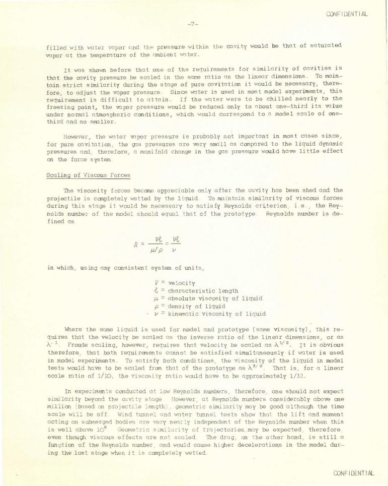
Scaling of Viscous Forces
The viscosity forces became appreciable only after the cavity has been shed and the projectile is canpletely wetted by the 1 iquid To nv::nntain similarity of viscous forces during this stage it would be necessar y to satisfy Reynolds cr~terion i e the Reynolds number of the model shou! d equal that of the prototype Reynolds number is defined as
R = v-t v-t =
J.LI p v
in which using any consistent system of units ,
V = velocity {. = characteristic length J.L =absolute viscosity of liquid p = density of liquid v = klnematic viscosity of liquid
Where the same liquid is used for model and prototype (some viscosity) , this requires that the velocity be scaled as the inverse ratio of the linear dimensions , or as A 1 Froude scaling, however, requires that velocity be scaled as Av 2
• It is obvious therefore that both requirements canna+ be satisfied simultaneously if water is used in model experiments To satisfy both conditions the Vi SCosity of the liquid in model tests would have to be scaled fran that of the prototype as A 3 2 That is for a linear scale ratio of ::./10 , t he v i»ca& i t y rati o would have to be approximately 1/ 32
In expe~1ments conduct ed a : l ow Reynol ds numbers , therefor e one should not expect sinulari ty beyond the o.:.v;. t·{ » tage However a t Reynol ds number s considerably above cne mi llicn .based on pro jec t ~e : ength geometri c simi lari : y moy be good al~hough the time sca l e Will be off W.nd tunnel a nd water tunnel tests show that the lift and moment acting on s ul:merged bodi es are v-ery nea r : y independen t of the Reynolds number when this i s well above 106 Geome:ric s.milu r ity of tra Jectories .may be expected ther efore even though vi scous effects are no+ scaled The dra g on '·he o her hand i s still a function of the Reynolds number and would cause h i gher decelerations in the model during the last stage when it s canple~ ely wetted
CONF IDENTIAL
ClJ'.FI DE NT I AL -8-
Scaling of Surface Tension
Surface tension forces may be appreciable in tests made to a very small scale and very low velocity With larger scale and higher velocity, and especially where surface seal 9oes not occur, surface tension forces are completely negligible by comparison with those of inertia and gravity . For instance, for a one-inch diameter projectile entering with a velocity as low as 20 fps, the inertia forces of the water are several hundred times greater than the surface tension forces Therefore, the formation of the cavity would be independent of surface tension . On the other hand, the inertia forces of t he atmospheric gas are of the same onier of magnitude as the surface tension forces Surface seal therefore would be affected by surface tensicn
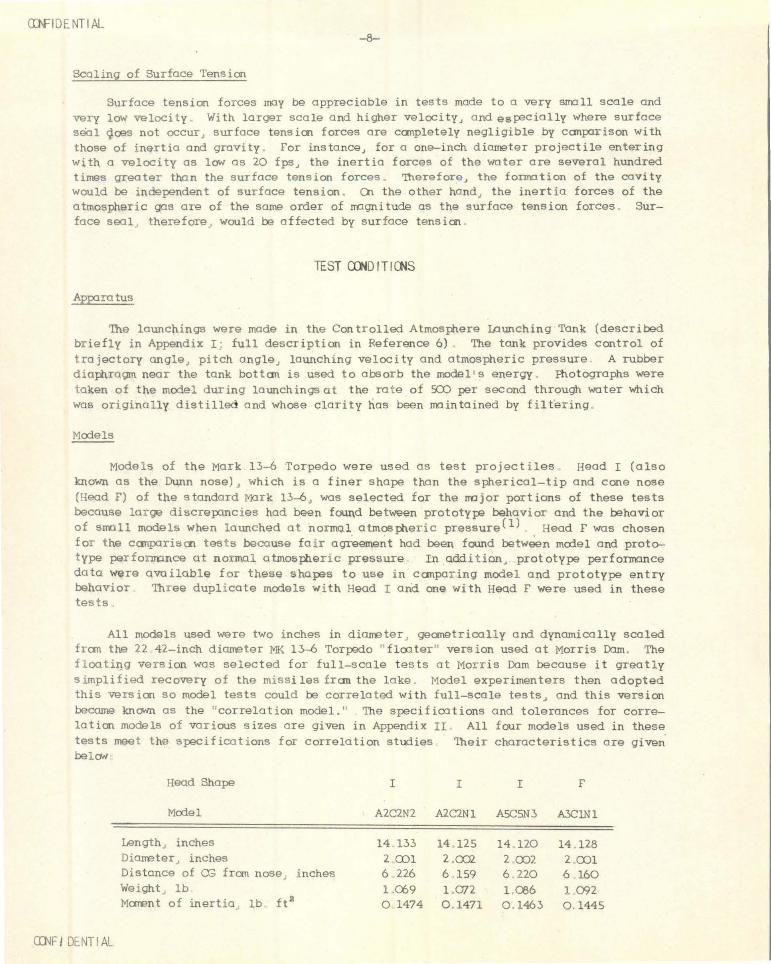
TEST <XHD IT I eNS
App1ratus
The launchings were made in the Controlled Atmosphere Launching Tonk (described briefly in Appendix I · full description in Reference 6) The tonk provides control of trajectory angle, pitch angleJ launching velocity and atmospheric pressure A rubber diaJ:hragm near the tank bot tam is used to absorb the mode 1 1 s energy Rtotographs were taken of the model during launchings at t he ra t e of ':OJ per second through water which was originally distilled and whose clarity has been main t ained by filtering
Models
Models of the Mark 13-6 Torpedo were used as test projectiles Head I (also known as the Dunn nose), which is a finer shape than the spherical-tip and cone nose (Head F) of the standard Mark 13-6, was selected for the major portions of these tests because large discrepancies had been found between prototype behavior and the behavior of small models when launched at normql atmospheric pressure(!) Head F was chosen for the comparison tests because fau agreement had been found betwoon mcrlel a nd prot~ type performance at normal atmospheric pressure In addition, prototype performance data were available for these shapes to use in comparing model a nd prototype entry behavior Three dupl i cate models with Head I and one with Head F were used i n these tes ts
All models used were two inches in diameter, geometrically and dynamically scaled from the 22 42-inch diameter MK 13-6 Torpedo flcater" version used at Morris Dam. The f l oating version was selected for full-scale tests at Morris Dam because i t greatly simplified recovery of the missiles fran the lake Model experimenters then adopted this version so model tests could be correlated with full-scale tests, and this version became knCMn as the "correlation model . " The specifications and tolerances for correlation models of various sizes are given in Appendix II All four models used in these tests meet the specifications for correlation studies Their characteristics are given bel aN
Head Shape I I I F
Model A2C2N2 A2C2Nl ASCSN3 A3C1Nl
Length, inches 14 133 14 125 14. 120 14 128 Diarreter inches 2 cxn 2 .CJJ2. 2 002 2 001 Distance of OG from nose . inches 6 226 6 159 6 220 6 160 Weight , lb l .Ch9 1 .072 1 Ql6 1 an MaTEnt of inertia lb ft2 0 1474 0 . 1471 0 1463 0 1445
CI:NF I DENT I AL

CDNF I GENT I AL -9-
The contours of the heads and afterbcx:l.ies of these models were held to the ± 0.002-inch tolerance prescribed for the diameter. The sections themselves were machined s lightly undersized to allow for the coat of paint which is about 0 .002 inch thick.
ThP models are made of duraluminum except for the 2-inch center sectionJ which is of s t a inless s teel. This center section is grooved for fastening in the launching chuck. The groove ~hould have no effect on the trajectory during the cavity stageJ ~!though it may have some effect after the cavity has been detached. The modelJ except for the center section, is covered with a light coat of white l acquer to produce n s1 ti sfactory image on thP film. Figures 1 and 2 show the outlines of either model or prot o t ype (dimengions g iven in terms of calibers) with Head I and with 4end FJ
b = ~ CALl BEP. K = 3.43
.J - - <t:--- --- - -- - ...1.... __
l)
.- - - - - - --f--- 2. 12~ CAL .. ---- - ....j..o---
------------7. I 81 CALl BERS----------- ----
FIG. 1-0UTLINE OF '-1K 13-0 .TOR F' EDO WITH HEAD I
E -----E--1- -1 ;;,;;.A,~~-6'i~=rs?r 8-4 55 CAL._j v~ RAD. CENTER I ('
8565 CAL. ~( PER LENGTH
f-·-----3.23E. CAL. 1.535 CAL 2.41 CAL.-------1 7 . 181 CALl BER.S -----------------~
~I G. 2 - 0 'TLINE or \ K 13-Q TORPEDO WtTH HEAD ~
respectively. Figure 3 shows a compar i son of the outline of !lead I wi th that of the s tandard i'1K 1.>-6 '1ead r. FigurPs 4 and 5 are photogrnphs of the two models. The s t ainless steel cente r sec tion and fastening groove are shown plain ly in the pictures. Figure 6 i s a sect ional view of a model with ~ead F, showing internal cons tructioo.
5TANOAQD N05E. (1-li::AD "I=")
-------
-------FIG. 3- COMPAR1SON OF CONTOURS HEAD I AND HEAD F
(X)IIFIDENTIAL
CQ\JFIDENTIAL -10-
FIG. 4- MODEL OF MK 1:r-6 TORPEDO WITH HEAD I
FIG. 5- MODEL OF MK 13-6 TORPEDO WITH STANDARD HEAD F
TRIMMI;R \J!;IG~.n
r--------6.970. -L 2.ooci' -~---5.:390
1-------------- 1-4. 360"-------------------!
FIG. 6- SECTI ONAL VIEW- MODEL OF ~K 13-6 TORPEDO WITH HEAD F
CnJFIDENTIAL

CONF ·DENT IAL -11-
Launching Cond1_~ ions
The launching conditions for these model tests were c~osen to give data for comparison with prototype da t a obtained by the Morris Dam Group of Naval Ordn1nce Test Station, Inyokern Prototype t ests were selected for which the Froude-scaled model launching cond1tions fall within the present operating range o f the Controlle'i Atmosphere Launch1ng Tank The tests are divided into two groups:
1 . Tests with Head I
The entry speed for all tests in this group wns set a t 119 .5 ft . per sec J corre sponding to a Froude-scaled prototype velocity of 4CO ft per sec for a geometrical scale ratio A of 1/11.21
The first few tests were mwle with a trajectory angle of 19° (the inclination of the full-scale launching tube at Morris Dam) a nd zero pitch The prototy~ data which were later obtained sho~ed t hat due to deflection of the trajectory during air flight·, the actual entry cond1 dons were abou t 20° trajectory angle and 1. 5° f111t ~itch (nose up with respect to trajectory ) The remainder of the tests were set for th@se angles The test result s showed that the entry a ngles varied from 19 ° to 20 8° trajectory and 0 5° steep to en flat pitch ond that these variations in trajectory a nd pi t ch angles had little effect on the s ubseiuent behavior of the
models
All launchings were made wi th an ai r atmosphe re Test~ were mode at nominal v~lues of atmospheric pressure of 1 3/4 1/2 1/4 1/11 and 1/22 atmospheres The value of 1/22 atmosphere corresponds to the lowest pressure obtainable with the present evacuation e1uipment The value of 1/11 atmosphere was se l ec t ed to correspond to the linear scale of the model The actual test conditions 11re prec;ented in Table I.
2. Tests w1th Head F
The entry speed for the six tests of this group was 103 ft per sec corresponding to a Froude-scaled prototype speed of 343 ft per sec The entry trajectory anqle was 19° a nd the pitch angle was 0 8° flat (nose up) Al l launchings we r e made with an air atmosphere Tests were made in pairs at three values of a ir pressure with absolu te pressu res of 1 a tmosphere 1/2 a trnos pher9, a nd 1/22 atmosphere.
Analysis of I:X!to
The analysis of the film record was mode with the sol e purpose of determining the elevation vi_. of the trajectory ':-d the inclination of the model s axis That is J only the x-ond z-coordinates and the model inclination were rPad although in s ame cases there were s li <t d1splacements in the y-direction
The trajectory and pitch angles were set to the neares t 0.1° The observed values were found to be different from the pre-set vr11ues oy same tenths of a degree , with a constant tendency toward steeper trajectories combined with nose up pitch This indicates that the present modPl rel80se mechanism releo~es the models a few tenths of a degree ahead of the prP set point
The experimentally determined traJectory a ngles are correct to of inclination) although rend to the neares t 0 . 1° s how samP sontte4 of a portion of the model by the bubbl~ , and indi s tinct photography
± 0 2 °. The values due to envelopment
tfowever not all
CDNF I DENT I Al
CONF IDENTIAL - 12-
TABLE I
Tank Run Model Entry Angles At mosphere No Used Tra j . Pitch In.Hg.Abs .
10 -i A2C2 N2 19 .0° o . 3 °F* 29 422 10-2 " 19 . 0 o . s F 29 . 29
11- 1 A2C2 Nl 19 . 0 0 . 2 r 29.25 -3 " 19 . 3 0 . 3 r 2 . 67 - 4 " 19 . 0 0 22.44 - 6 " 19 0 0 15 . 30 - 7 19 .0 0.3 r 29.28 -8 " 19 .0 0 29 . 28 - 9 19 . 6 0 . 6 r 15.28 - 10 "• 19 . 2 1.0 r 2.67•
- 13 " 20. 4 0.6 r 2 . 67 -14 " 20. 0 0.1 r 2 . 67 - 16 " 20. 8 1.0 F 1. 35 -19 " 20. 8 1.2 r 1. 35 - 20 "· 19 .0 o . 5 S** 7 . 48 - 21 " 19 . 0 0 7 . 48 - 22 19.3 0 . 7 r 22 . 44 - 23 " 20 . 1 o. 5 r 29 . 2 5 -24 " 20. 1 0 . 4 r 29 . 26 -2 5 " 20. 2 2 . 3 F 29 ·. 23 -26 " 20 1 1.7 r 2 . 67
12- 1 ABCBN 3 20. 1 0 2 . 67
* F fla.1: =Nose up w~th t res~ct j t o trQject ory **S StE>ep = Nose down with respect to trojectory
Pressure Std.Atms .
0 . 977 o. 979
o. 978 0 . 089 0 . 751 o . 512 o. 979 0. 979 o. 511 0 . 089 0 . 089 0 . 089 O.Q45 0.045 0 . 250 0.250 o. 7 51 0. 978 0.978 0.977 0 . 089
0.089
Entry Velocity
ft/sec
119 . 5 "
" " " "
" " " "
" " " " "
"
"
o f the roughness of the inclination curves is due to scatter of data. The model definitely does bounce up and down as it moves along the trajectory.
Coordinate poRitions were rend to .01 diameter. Here) again) some uncertaintieR a rise due to indistinctness caused by the bubble ond other factors) as well as the effect of movement of the model from the launching plane . The readings, nPVerthelessJ are correct to within± 0.05 diameters in most oases and to± 0 . 1 diameter under the worst cond itions
TEST RESULTS
The primary objective in thi<~ investigation was to study the over-<111 effect on projectile behavior of variations in atmospheric pressure . Emphasis is placed) the~eJ on the resulting trajectory rather than on details such as whip at ent ry or orientation of the model within the cnvity . The trajectory angle and pitch angle at entry were determined for each launching as o check of the pre-set launching conditions . For the underwater tra jectory ) tho film record was analyzed only for the coordinate position in the vertical plane and inclination of the model . The entry speed was taken as the controlled launching speed .
The dis cussion of the test results for each of the two shapes tested is pr~sented sep1rately .
CDN FI DENTIAL

CDNFIDENTIAL -1>--
4ead I
Significant results ore observed when the average trajectories nt the various pressure conditions ore compared, as is done in Figure 7. Analysis of the entry trajectory and pitch angles showPd relatively little variation from launching to launching so that these overage trojPctories ore for comparable conditions of entry angle, pitch angle, and speed. Therefore, any differences in these trajectories must be attributed to the other variable, the atmospheric pressure. Thus, the consistent progression from a downward curving, diving trajectory a t on air pressure of one atmosphere to the sharply upword curving, broaching trajectory nt 1/ 22 atmosphere represents the effect of the change in tank air pressure alone.
It i s then interesting to canpnre the overage model trajectories ~rith an overage prototype trajectory for similnr entry conditions based on the Froude scaling of velocitv. in Figure 8.
lJ.J (..) <(
0 u.. a:: ::> CJ)
~ 10 0
_J lJ.J CD
CJ)
a:: 20 lJ.J 1-lJ.J ~ !:!
30 0 I
:X:
~ ~ ~ L0
f,ATM ~ vv ~ ..___ ---.... II
\ ~ ;--- t-- , TATN ---~™
\ " ~ ATN
1'\iATM
'-.J \
1-Q.. lJ.J 40 0 0 90 10 20 30 40 50 60 70 80
HORIZONTAL TRAVEL- DIAMETERS FROM ENTRY POINT
FIG. 7- MK 13-6 TORPEDO WITH HEAD I EFFECT OF ATMOSPHERIC PRESSURE ON AVERA GE MODEL TRAJECTORIES
lJ.J (..)
lt 0 a:: ::::> CJ)
~ 10 0 ...J lJ.J CD
CJ)
0:: 20 lJ.J 1-w ~ !:! 30 0
I :X:
~'--_
~ L4 I J.._---' Jii' PIIOTOTYPE
~ ~ L-:::::::: ~ ~ ~ I: ATN
\ ~ t-- ;- i-ATN :.:...--
R"™ \ "'
~AT/ol [\t"™ "I
1-a.. 40 w
0 0 10 20 30 40 50 60 70 80 90
HORIZONTAL TI-IAVEL- DIAMETERS FROM ENTRY POINT
FIG. 8- ~~ 13-6 TORPEDO WITH HEAD I AVERAGE TRAJECTORIES OF MODEL AND PROTOTYPE
CDNFIDENTIAL

illFIDENTIAL -14-
Particular attention is directed to a comparison of the average prototype trajectory with the overage model trajectory at 1/11 atmosphere. It will be recalled that theoretical consideration'> show that with the scale ratio usedJ model launchings should be ~ode with on atmospheric pressure of 1/11 atmosphere. It will be noted that there is closer correspondence between the overage model trajectory at 1/11 atmosphere and the prototype traj ectory than between any other model trajectory and the prototype trajectory, even though the correspondence is not perfect. It is interesting that the model trajectory lies on different sides of the prototype trajectory at different pointsJ being first above it and then beneath it. Nevertheless, for at lea s t 70 diameters of horizontal travel, the model trajectory corresponds to the prototype trajectory within 2.5 diameters, which is approximately eTUal to the spread between repeated launchings of both model and prototype. This reasonably close correspondence between scaled model tests and prototype performance has been obtained by scaling of speed according to the Froude low, and the atmospheric pressure according to model scale, without regard to scaling of the atmospheric densityJ since the air density varied wi th the pressure.
These results lead to the conclusion that reasonable similtiude between model and prototype trajectories can be obtained in tests of the JVPrk 1.>-6 Torpedo with Head I at 19° to 21° trajectory angleJ with pitch angles between 0 .5° steep and 2°flat,and prototype speed of 4CD ft. per sec. by Froude scaling of speed and by scaling the atmosroeric pressure according to model scale . However, it seems reasonable to expect that the range of applioo tion for this scaling principle should be quite broad. further work is necessary at different angles, speeds, scale ratios and shapes to detennine working limits.
The average model trajectories and envelopes of the test trajectories from which they were derived, are presented as Figure 9. The fact that there is an overlap of data for s ome of the pressure conditions i s evident. Cn the other hand, the envelope for the 1/4 atmosphere condition is a line despite the fact that two runs are represented. This is the same number of runs as represent the very wide spread at 3/4 atmosphere. The detailed individual trajectories and model inclination curves have been grouped by pressure condition and ore presented as Figures t) through 16J for the pressures of 1, 3/4, 1/2, 1/4, 1/11 and 1/22 atmosphere. Each curve is identified by two
1&1 0
: a: ~ (/)
~ 1&1 CD
~ 20r-----~------~----42~~~~~~~~------~------+-----~------~------~~ 1&1 1-1&1 ~ <t 0 30 r-----~-------r--~~~~~~~~~~~~--~------+-----~------~------~~ I
:I: 1-~
~ 40 ~----~o-------.o~----~2~o------3-oL------4~o------~5L-o _____ sLo------7~o-------aLo------9~o--_J
co-JF I DENT I AL
HORIZONTAL TRAVEL- DIAMETERS FROM ENTRY POl NT
FIG. 9- MK 13-6 TORPEDO WITH HEAD I TRAJECTORY ENVELOPES AND AVERAGE TRAJECTORIES

(X}lFIDENTI.Al
- 15-
figures . The first gives the measured entry tra jectory angle . The second gives the measured entry pitch angle . It wi ll be remembered that all launching speeds were set at 119 .5 ft . per sec . Although the trojectories as presented are defined by points" these points are only a fraction of those whi ch could have been obtained from the photographic record had minute analysis of each trajectory been the objective .
In Figure 10" we see that seven of eight launchings at a pressure of 1 atmosphere produced data which fall within a spread of five diameters even at the end of the measured trajectories . en the other hand" one run devia ted so far from the others that at the end of its trajectory the model was about 10 diameters from the nearest corresponding trajectory . These launchings were made with two models, there being two runs with one and six runs with the other . The e rratic trajec tory was the first launching of the model with which the six runs were ultima tely made" thus eliminating the possibility of same undetected difference in model s hape as a cause of this variation . However" the difference could have been in s ome surface property of a newly painted model as compared with one subjected to r epeated handling. It is interesting to note that one other trajectory which differed from others in its group ( trajectory with earliest broach in Figure 14) also resulted from a launching with a newly painted model . This indicates the advisability of investigating the effect of surface finish on model behavior .
Thi s group of launchings represents three nominal launching conditions -- 19° and 20° trajectory at 0° pitch" and 20° trajec tory with 1-1/2° flat pitch . The actual trajectory and pitch angle data are tabulated below in Table II" in order of decreasing curvature of trajectory" with those for the most curved trajectory first and the least curved one l ast:
TABLE II
Trajectory Angle
19 .0° 20. 1 19 .0 20 1
19 0 19 0 20. ~
19 0
Pitch
0.3<>r 0 . 4 F 0 0.5 F 0 . 5 F 0 . i) F 2.3 F 0 . 2 F
If only the first seven launchings are considered and the widely deviating trajectory is ignored" it is seen that the spread of the trajectories at the same condition of 19 .0 ° entry trajectory angle and 0 3 ° flat entry pitch angle includes all trajectories except the extreme one at 20 2° trajectory angle a nd 2.3° fla t pitch" which is excluded only by a fraction of a diameter of horizontal travel. However" even then the maximum spread between these trajectories" a t 19.0° trajectory a nd 0.3 ° flat pitch, at their ends, is of the onjer of only 3 diamet ers
• Because of the relatively smell r :'read of data for the seven t es t s " it i s concluded tha t small changes in trajectory and/or pitch angle had little effect on the trajectories produced . The reason for the l arge deviation of the eighth trajectory i s yet to be determined .
ffi'JFIDENTIAL

CDNFI DENT I tL
-40
-20
0 (/) w w a:: 20 (.!) w a I z 40 0
~ z 60 _J (...)
z 80
100
120
w (...)
<t LL. a:: ::> (/) 0
~ 0 _J w CD
10
(/) a:: w 20 ._ w ~ <t 30 a I
I ._ Cl..
40 w a
CO'-JF I DENT I AL
-16-
I NCUNATION
..... ......... w· -~·.
~. . 19.0", 0.2• Fl
~r-20.2", 2 .3"F
...... HORIZONTAL---......_ ~ r::r· 19.0~0.3"F-
~-OF+ INCLINATION 19.0", o•-r- \ ~
~ ~19.0", O.!S"F
·~.-i " ~ 20.1•, o.4• F~ 1a
'
)' r--20.1•, o.s •F PROJECTILE AXIS
I 0 10 20 30 40 50 60 70 80
HORIZONTAL TRAVEL- DIAMETERS FROM ENTRY POINT
~ TRAJECTORY
" I
~9.0~. 0 .2• F
, . ~o·,o.•••
19.0", 0.3·~ f-L \ 19.0 ", 0.5"F ~ r- 1 1 · 19.o~ o·
!• !? 2 0. 1", 0.4"F
I· T~ ' ""'- b I I ~ 20.2", 2 .3" i
20.1• , 0 .5"F
0 10 20 30 40 5 0 60 70 80
HORIZONTAL TRAVEL- DIAMETERS FROM ENTRY POINT
FIG. 10- MK 13-t T0RPEDO WITH HE AD I INDIVI DU AL MODEL TRAJECTORY AND INCLIN ATION CURVE
AIR PRESSURE l ATMOSPHERE
90
90

(/) lJJ lJJ 0:: C> lJJ 0
I z 0
~ z _J (.) z
~ 0 _J lJJ CD
(/) 0:: lJJ
to ~ ~ 0
I ::r:
CCNF I DENT I AL
-17-
INCLINATION -40
-20
0
_.. A
20
40
60
80
100
. ="" -iii
N ~~ ..a ·"'
~ \!1 \:T
~ -19.0• o• . ~
~ ~19.3•, 0.1• F ' HORIZONTAL--------......
.A ~-OF+ INCLINA"TlON
~~ ~
8.
&I ~ .... PROJECTILE AXIS
120 0 10 20 30 40 50 60 70 80 90
HORIZONTAL TRAVEL- DIAMETERS FROM ENTRY POINT
0~ TRAJECTORY
~ IOr----;-----+~~~Q---4-----+---~~--~-----+----~----~~ ~ ~v-19.o•,o•
20~-1--~---+~~~·--+~--· ~-~--~--~--~--~--~ · ji9.3•,o.7·~
30~----~----r----r~-~~· -+----+~--~-+----4---~----~----~ ~ ' e.\ A
~ 40L---~~--~----~----~-----L-----L--__ _L ____ _L ____ _L ____ _L~
0... lJJ 0
0 10 20 30 40 50 60 70 80
HORIZONTAL TRAVEL-DIAMETERS FROM ENTRY POINT
FIG . 11 - MK 13-o TORPEDO WITH HEAD I INDIVIDUAL MODEL TRAJECTORY AND INCLINATI ON CUR VES
AIR PRESSURE 3/4 ATMOSPHERE
90
aNF I DENT I AL

CWF I DENT I t>L
-40
-20
0 (f)
w w 0::
20 ~ w 0 I z 40 0 i= <( z _J 60 (..)
z
80
JCO
120
w (..)
~ 0:: ~ 0 (f)
3: 0 _J 10 w (lJ ' (f)
0:: 20 w
f-w ~ <( 30 0 I
I f- 40 a.. w 0
CQ'.JF I OCNT I t>L
-18-
INCLINATION
. . ~ .. ~ .. .--B .
r=·
~ : ~rg.o•,o• ~
~~. "-0 ~
.../>; .A A
/'-'- "" Lrg.s•, o.s•F
HORIZONTAL~ ......
~-OF+ INCLINATION
~ ... PROJECTILE AXIS
0 10 20 30 40 50 60 70 80
HORIZONTAL TRAVEL- DIAMETERS FROM ENTRY POINT
~. TRAJECTORY
~ ~ . . :::........,
L.o~ ~o· . .
\a. ~
0 10 20 30 40 50 60 70 80
HORIZONTAL TRAVEL- DIAMETERS FROM ENTRY POINT
FIG. 12·- MK l~ TORPEDO WITH HEAD I INDIVIDUAL MODEL TRAJECTORY AND INCLINATION CURVES
AIR PRESSURE 1/2 hTMOSPHERE
90
90

-40
-20
0 (/)
w w cr 20 (!) w a I
z 40 0 1-<{ z 6C :J (.)
z 80
100
120
w (.)
Lt 0::: => 0 (/)
~ g 10 w co (/)
0::: 20 w 1-w ~
30 <{
a I :r 40 1-a.. w a
CONFIDENTIAL -19-
INCLINATION
II .Jill
~.o•,o•
._--4r~ /
. . . ~"'"C J:l~ ~ "' 19.o•, o.!5 5
A
..... HORIZONTAL~
~-OF+ INQ.INAnON
~ .... PRO.IECTILE AXIS
0 10 20 30 40 50 60 70 80
HORIZONTAL TRAVEL- DIAMETERS FROM ENTRY POINT
l~ TRAJECTORY
~ ~ ~•Lo• ~ ...... A/ .t~~ Ll9.o1, o.!5 5
0 10 20 30 40 50 60 70 80
HORIZONTAL TRAVEL- DIAMETERS FROM ENTRY POINT
FIG. 13- MK 1~ TORPEDO WITH HEAD I INDIV1DUAL MODEL TRAJECTORY AND INCLINATION CURVES
AIR PRESSURE 1/4 ATMOSPHERE
90
90
cnJF I DENT I t:l

~F I ILNT I ti.
-40
-20
0 (f) w w a:: 20 t!) w 0 I z 40 0 1-<X: z _J 60 (..)
z 80
100
120
w (..)
~ a:: ::::> 0 (f)
~ 0 10 _J w co (f)
20 a:: w 1-w ~ <( 30 0 I
J: 1- 40 0.. w 0
C(}lF I DENT I ti.
-20-
INCLINATION
._---2o.l.. o• / ~/-Vxl ~20.0~ O.I"F
k9.2•,1,C1"F '\ v [7 M ./ ..... _.., . . .
" ~ 20.4•,0.6~ .....,: -s.. .....
.-...,· f'. ~ ~ ~·~-~ 4o.••,r.7•F .0... .. .. ---
....... HORIZONTAL~
~-OF+ INCLINATION
~ ... PROJECTILE AXIS
0 10 20 30 40 50 60 70 80 90
HORIZONTAL TRAVEL- DIAMETERS FROM ENTRY POINT
~0.1•,1.1•F TRAJECTORY "'20.0•, O.I•F
~ ~ i-19.3~031F 20.1•,o•~ / ~ -.c8, .<\ /. ~ .2•,1.o•F ~ A ~ ~ -. . . .. . . -,.
"""' '-- 20.4°, 0.60f
0 10 20 30 40 50 60 70 80 90
HORIZONTAL TRAVEL- DIAMETERS FROM ENTRY POINT
FIG. l~- MK 13-6 IJRPEDO WITH HEAD I INDIVIDUAL MODEL TRAJECTORY AND INCLINATION CURVES
AIR PRESSURE 1/ll ATMOSPHERE

LLJ 0
~ Q: ::::> (/)
:it
CDNF I DENT I Al -21-
Although the two launchings made at 3/4 abnosphereJ Figure 11~ produced differing trajectories~ no further investigations were mode at this condition. It will be noted that the trajectory and pitch values were a bit different for the two runs. The use of this pressure condition was merely to establish the trend of on average trajectory as the tank air pressure was varied. The same considerations apply to the curves at 1/2 atmosphere in Figure 12 in which the divergence is smaller.
How closely data can be reproduced same of the time is illustrated in Figure 13J which shows results of launchings made at 1/4 atmosphere. One run is indistinguishable from the other for 9J diameters of horizontal travel . In this instance~ as in some othersJ the length of trajectory recorded in one launching differs from another. This is the result of difficulties in conducting the tests~ such as loss of the film record in one of the cameras.
Six launchings were made at the condition of major interest. This is the condition of 1/ 11 abnosphereJ which is the theoretically correct pressure. The individual curves are presented in Figure 14. The launchings wero made with two models. One model was damaged when it broached on its first run. It produced the earliest broaching trajectory. Whereas the other model produced consistently flat trajectories to 70 diameters of horizon tal travelJ this ones tar ted its u'f"'Ird travel with only a short length of flat trajectory. The data for the second model show no spread greater than 2 diameters for 75 diameters of horizontal travel . All trajectories show a spread no QTeoter than 5 diameters out to a distance of 70 diameters of horizontal travel. This virtual duplication of trajectories is also interesting because the launchings represent a range of entry trajectory angles fran 19 . 2° to 20.4° and entry pitch angles fran 0° to 1.7° flat.
The canJXlrison between the model trajectories at 1/11 atmosphere and the prototype trajectory is made in Figure 15. The prototype trajectory is approximated to within 2 diameters throughout its full length by the earliest broaching model trajectory. It is approximated to within 5 diameters by all trajectories to 70 diameters of horizontal travel.
0 ~ '
~ ~ __, 7 "2 --::..-0 10 ..J "' (;)
UJ (J)
(/)
a: 20 LLJ t-LLJ :::!! <t 0 30
I :r t-a.. LLJ 40 0 0
PROTOTYPE
10 20 30 40 50 60 70 80
HORIZONTAL TRAVEL- DIAMETERS FROM ENTRY POINT
FIG. 15 - fiK 13-{) TORPEDO WITH HEAD I
COMPARISON OF INDIVIDUAL MODEL TRAJECTORIES AT 1/11 ATMOSPHERE WITH PROTOTYPE TRAJECTORY (POINTS SHOWN ARE FROM PROTOTYPE TESTS)
90
CDNF I DENT I AL

cx:NFI DENT I ftL
-40
-20
(/) 0 lLI lLI 0::: (!) 20 lLI 0 I z 040 r-<t z ....J60 <.:> z
80
100
120
lLI 0
~ 0:::
~ 0
~ ....J 10 lLI m (/)
0::: 20 lLI r-LLI ~ ~30 0 I
-22-
INCLINATION
c/o.e•, 1.2•F ~ ....
h. l>o.-«: ~ --~'~A "' ~_llllf" "'"' r-:- ....
~ r L 2o.a•, 1.o• F
~
,.~ ~ ~-~
r;)W; .
_..._, HORIZONTAL_~
~-OF+ INCLINATION
~ '
PROJECTILE AXIS
0 10 20 30 40 50 60 70 80 90
HORIZONTAL TRAVEL- DIAMETERS FROM ENTRY POINT
~ TRAJECTORY r:,.20.8~ 1.2• F
~ ~ ~ ~01
~~ · ... [;): -.,._:"" 2o.a•,1.o•F .. ..
~ - . . """
:z:: r-40 ~ 0 10 20 30 40 50 60 70 80 90 o HORIZONTAL TRAVEL- DIAMETERS FROM ENTRY POINT
ro.lF I DENT I ftL
FIG. 16-- MK 13-6 TORPEDO WITH HEAD I INDIVIDUAL MODEL TRAJECTORY AND INCLINATION CURVES
AIR PRESSURE l/22 ATMOSPHERE
w 0
a:NF I DENT 1/tl.
-23-
~ 0
~ / a:: ::::> (/) ~ ~ ~ 0 10 _J
~ <:
d:l 0-0
w CD
(/)
ffi 20 1-w ::1!! <t 0 30
I :I: 1-a.. w 40 0 0 10 20 30 40 50 60 70 80 90
HORIZONTAL TRAVEL-DIAMETERS FROM ENTRY POINT
FIG. 17 - MK 13--6 TORPEDO WITH HEAD I AVERAGE TRAJECTORY AND TEST POINTS FOR TWO PROTOTYPE RUNS
ENTRY SPEED ijQQ FPS
The two prototype t es t runs which were used to obtain the average prototype curve ore shown in Figure 17. It is seen that rt 55 diameters of horizontal travel the vertical spread between the test points i s about 3 .5 diameters.
These results indicate thatJ for the projectile and entry conditions used in these testsJ reascnable similitude is obtained between the trajectory of the prototype ard the trajectory of small models launhhed at Froude-scaled speed and atmospheric pressure scaled according to the linear scale of the model.
The data of two launchings at 1/22 atmos.phere are sha-m in Figure 16. The trajectories show th~t the model has no tendency to run horizontally. The model broached in both runs. It is seen that a reduction in atmospheric pressure below the theoretically correct value causes the model trajectory to shift away from the prototype trajectory t~rd a fas·\Er recovery and brooch (see Figure 8).
Turning from inspection of the trajectories to a consideration of the curves of inclination, it is seen that there is a specific inclination curve corresponding to each trajectory. Sim~lar trajectories are associated with similar curves of inclination. The pattern of inclination values is different for each pressure condition. The differences between the curves of inclinati~n at one pressure ore seen to be even more pronounced than the differences between trajectories. A more detailed study of inclination and pitch angles may become a fruitful source of information on projectile behavior.
No detailed study has been made so far of the inclination curves, nor have vnlues of the trajectory angle and pitch angle been detennined except at the entry point) since the emphasis in this work has been upon a s tudy of trajectories.
OONFIDENTitt...

ffiNFI DENT I AL -24-
Head F
The tests with the 2-inch model of the t1K 1}-.-6 Torpedo with the standard. head were made sane months ago and were reported in a memorandum report( 7 ) . The results ore included in this report for Gomparison with the Head I tests, mainly to point out the great difference in sensitivity of the two shapes to variations in atmospheric pressure.
In Figure 18 are shown the trajectories resulting from three sets of duplicate launchings made at air pressures of 1, 1/2, and 1/22 atmosphere . For all these tests the entry angle was 19°, the initial pitch angle 0 . 8° flat, and the entry veloci ty was 10~ ft per sec corresponding to a prototype velocity of ~4~ ft. per sec
It is seen that the spread between any two trajectories at the same pressure is nowhere greater thoR one diameter, and that the spread of all six trajectories is not greater than about 2 diameters It will be noted, also, that there seems to be a reversal in trend in that in ~oing from 1 atmosphere to 1/2 atmosphere the trajectories ore lowered whereas a further reduction of pressure to 1/22 atmosphere causes the trajectories to rise again . Additional tests with this shape ore now in progress to investigate this behavior in greater detail These tests , made at an entry speed of 120 ft per sec .• also show this reversal in trend.
The insensitivity of this shape to variations in atmospheric pressure is very striking when compared to the great sensitivity of Head I, since the difference between the contours of the two nose shapes is not very great , as may be seen in Figure ~
The prototype trajectorY. shown in Figure 18, is an average trajectory for 16 launchings taken from Figure 9 ( 27) of reference 8 It is seen that all model tra jectories came within two diameters of vertical displacement from the prototype trajectory This is in agreement with the findings of other experimenters who obtained good similarity to prototype trajectory with small unvented models of the MK 13-6 Torpedo with standard head when launched with Froude-scaled entry velocity and without scaling atmospheric pressure . (Reference 1) . It is interesting that there isalmost perfect agreement between the prototype trajectory and the two model trajectories taken at 1/22 atmosphere Among the three pressures used in these tests, the 1/22 atmosphere is nearest to the theoretically correct pressure of 1/11 atmosphere This could be a fortuitous coincidence Cn the other hand, it is possible that with this nose shape even small differences between trajectories are significant Cnly further investigation can settle this point
Reproducibility of Trajectories
In addition to the difference between the sensitivities of the two nose shapes to variations in atmospheric pressure, there is also a marked difference in the reproducibility of trajectories resulting from repeated launchings under the same conditions With Head F, the same initial conditions produce trajectories that are alike to within one diameter With Head I, on the other hand, reproducibility is good under low atmospheric press~re) but at higher atmospheric pressures there is considerable spread between trajectories resulting from supposedly identical initial conditions At presen t only a tentative explanation can be offered for this difference in reproducibility
As was indicated earlier in this report in the case of Head F the flow 1n the cavity stage separates cleanly from the body and stays clear of the body until the projectile changes orientation in the cavity so that the tail comes in contact with the cavity wall However, with the finer shaped Head I , when small models are launched
a::NR DEN T I AL

8 z , 0
92 ~
f!!
0
r; ' .. t; r ~ 0
1 l ~ 10
~
..,"")., ">';, r.-,
r--""""
-I-~ ~
MK 13-6 TOR'PEOO • HEAD F ENT'RV ANGU: ~ IP• PIT04· 0 6e~\.AT 1'1C()(L Ya.OC.ITY 10!> FT/>EC
~~T~5g "'"'"'\343fT/ .. C.
SYMOO<. RUN "~S~l --- ::~ llolf105PM£R£ -·------.------o- ::~ •/2-0< ---~ ---·---o-· ::~ 1/lUIIO>lPII]t( -;---+-·
•Tnr<PC
roo ~ tO
1- 1-f- - 1-1-
~ k
~ !;;...
f---- ~
·~
,__ . } 1- 1-1--1-- 1-
--- 1- 1- 1-1- f- - 1-1-- - -
+ 1- r- r-~ 1- -I- 1- 1--
H-~ ll-- 1-1-1- 1- ' ... 1- 1- + ~ F.;- - j -
1/l~ Al ~ ---- - - t- - _ L...,.om< +- ~ ~---r- - ~ h- T
-~ ·- -- ~- - -- ~ - ~-- ---- --1-- -- -- --- ~-1--- ··- ··• ~ 1,>-"Vz"""""'E~~£
ZfJ 2~ :lO ~ .0 0 50
~OA.IZONTAL. OI~TANC'- IN O.AM,T£.QS
FI G. 13- MK 13-6 TORPEDO WITH HEAD F MODEL TRAJECTORIES AT VARIOUS ATMOSPHERIC PRESSURES COMPARED WITH PROTOTYPE TRAJECTORY
.. !>ti,rt"<: ~io<
60
I
~ I
c;;o
§ , 0 m :z ~
l> r

CGJF I DENT I AL
under full atmospheric pressure, the flow does not stay clear of the body . The high velocity flow of water along the cavity wall pumps out the air in the narrow space between cavity and model on the underside of the nose . This creates an under-pressure and sucks the underside of the cavity in towards the model so that the water clings to the model (see Plate 14 of Reference 1). This transition from separated flow to clinging flow, like many other sudden transitions from one flow regime to another, is probably somewhat unpredictable That is, very small and so far unmeasurable differences between one test run and another may " trigger" this transition and couse the time of
. its occurrence to differ slightly from run to run. These slight differences may be in water surface configuration due to ripples, or in model surface conditions such as surface finish or oiliness .
The same suction force that causes the change in the flow pattern also pulls the model nose downward and causes the model to dive . It is possible, therefore, that the time of occurrence of this transition is important enough to bias the remainder of the trajectory and to produce appreciable differences. This may explain why, with Head I under air pressure between half atmosphere and a full atmosphere, there is considerable spread between trajectories from the same entry conditions . At air pressures of 1/4 atmosphere or less, variations in air pressure within the cavity could not be very significant, and reproducibility of trajectories is improved
TWo models were used in the group of eight tests made at a pressure of one atmosphere. Seven of these show good agreement among themselves and the eighth deviated from the remainder Five of the seven tests were made with one model and two with the other . This indicates that the manufacturing tolerances are close enough for the behavior of one model to be indistinguishable from that of another The one deviating trajectory was the first run of a newly painted model, the same one with which the other five runs were later made. Another newly painted model, launched at 1/11 atmosphere, also produced a trajectory which differed from the others in that group. It appears, therefore, that, at least for projectiles with noses of fine shape, the surface finish may have a noticeable effect on entry behavior.
CONQUSI 00
The detailed cooclusions concerning the effect of a tmosr:neric pressure on the entry behavior of the two shapes tested ore given in the abstract at the beginning of this report. The following paragraphs contain a more generalized statement of the conclusions, and suggestions for further investigation.
1. The entry behavior of streamlined projectiles with fine nose shapes (such as the MK U-6 Torpedo with 1-Iead I) cannot be simulated by srnall models launched under full atmospheric pressure even though the speed is correctly scaled
according to Froude's low.
2 . The entry behavior of fine-nosed projectiles can be simulated by small models (at least within the range of cooditions covered by these tests) if the velocity is scaled according to Froude's law and the atmospheric pressure is scaled in proportion to the linear dimensions .
3. Analysis shows that in order t~ model some of the phenomena accompanying water entry, such as surface closure, it is necessary to maintain the density of the atmosphere used in model tests equal to that of the prototype Since the pressure of the atmosr:nere in the case of the model should be lower than that
ern R DENT I AL

OONFIOENTIAL -27-
of the prototypeJ this requirement indicates the use of an atmosphere of heavy go ~ in model tests. The tests reported herein show that in the case of the obligue entry of elonQJted projectilesJ thi9 requirement does not have to be fulfilled i .e .J on air ntmosphere may be used in modPl tests and the atmospheric den~ity may be allowed to vary linearly with the pressure . From this it may oe inferred Pither that surface closure does not occur~ or that it occurs late and does not affec t the subsequent behavior of the projectile.
4. The entry behavior of pro j ec tiles with ~phere-typed heads (e.g.J Head F) ente ring with pitch angles of one degree or less is only very slightly affected by a tmo9pheric pre9~ure. From this it may be inferred that model tests may be made at any atmospheric pressure . HoweverJ this is probably true only for a limited range of condition9 .
Furthe r investigation is necessary to determine the limits of applicability of t hese mode ling l aws . It is k~ownJ for instanceJ that small models of the MK 13-6 To rpedo w1 th Head F launched under full atmospheric pressure and with various pitch a ngles hove a c ritical pitch angle that is different from that of the prototype. The critical p1tch angle is the value of the steep (nose down) pitch at which the behavior of the proj ectile changes abruptly from the upturning trajectory resulting from flatter pi t ch a ngles ton down-turning trajectory resulting from steeper pitch . The Launching Tbnk i s now engaged in another series of tests to determine whether the critical pitch a nglP can be reproduced by models launched with Froude scaled velocity and with atmospheri c pressure reduced in proportion to the linear dimensions . It is felt that an a f f irMative a nswer to this question~ added to the results of the present testsJ would just i fy cons idera ble confidence in this procedure for modeling ~ter entry phenomena.
Anothe r important aspect of the problew. yet to be investigated is that of modeling whi p , i . e , the ra pid c hange in angular veloc ity following nose impact. This is one of the mos t importa nt factors in determining the water entry behavior of elongated projectiles Indirect evidence on this point will be obtained from the critical pitch s tudy now in progres sJ but this problem deserves more detailed examination.
In f ormat i on on the whip characteristics of various nose shapesJ combined with data on t he f or ces ac ting on projectile components during the cavity stageJ would form the bas i s for quantita tive analys i s and fairly reliable prediction of the entry behavior of pr ojectiles A s tudy of the forces acting on projectile components during the cavity s tage i s now in progress in the Free Surface Water Tunnel of this laboratory.
CONFIDENTIAL

CDN R DENT I ti.. -28-
APPENDIX I
THE CQIJTRCllED ATh'OO'HERE LAUN011NG TMI<
The Controlled AtmosJ:here Launching Tank was designed primarily for the study of the hydrodynamic factors involved when a body troveling freely through a gas, such as air, strikes a water surface and enters the water . Since it is sometimes necessary to control the gos pressure and density when studying hydrodynamic phenomena occurring at a surface between a gas and a liquid, the tank is a closed pressure vessel . It can also be used for other studies requiring similar equipment .. such as explosions under water .
The tank is a cyl inder of welded steel constructi on, 13 feet in diameter and 3D feet long To one side of it is attached a section of a smaller cylinder for mounting sane of the recording apparatus In notll¥ll operotion, t he tank is filled with ......ater to a depth, of about 10 feet A launching wheel is moun t ed on the underside of a large hatch cover on t op of the tank A device for holding a test model is located on this wheel By adjusting t he speed of rotation of the wheel the model can be launched centrifugally at any desired !speed up to 250 ft per sec The path of the model at the instant of launchi ng can be adjusted to any angle be tween horizontal and vertical The angle of the model with respect to the selected path can be adjusted to any angle up to ± 10 degrees
The path of the model throuQh the gas above the s.urface of the water and under ......ater is recorded by two groups o f hicjl speed 35oin motion pi cture cxuneras operated at constant speed by a synchronous motor The requirements of the necessary high--speed }¥\otography ruled out conventional methods in whic::h the interior of the tank would be illuminated continuously and light admitted inte~ittently to the film by means of a s}\utter , The o:uneros_ have no shutters Exposures are mo.de by intermittent iilumina tion of the i n terior of t he tank. with special ( Edgerton t ype} flash lamps The number of exposures can be varied from 5(X) to YX:f:) p-er second The light flash duration is about one million t h of a second The fields of view of adjacent cameros overlap to such an ext ent that t he model is photographed by at least two of them duri ng each exposure This· makes it possi ble to reproduce the path of the model by stex-eoscop ic observotion of the projected innges The film is spliced to fonn one continuous loop in each camera magazine In operation the cnmera shaft is accelerated slON'ly to pr e-vent fi 1m breakage ~
The flash l~s for phot ographing t he underwater trajectory are housed in lucite tubes loooted in the· bul ge which atao oorrie$ the under......ater trajectory cameras
The tank i s lined wi th a pol yvinyl chlori de plastic to preven t corrosion products f rom fouling the wa ter It is equipped with u lKrcrviol et lamps to i nhibit bacterial growth and wi th a fi_.trati on system t o r emove suspended matter from the water These precaut ions are necessary because the underwater light path for photography is crbout 24 feet
CINFI DENTI!i..

CX>NFIDENTIAL - 29-
CXlNF I DENT I AL
CONFIDENTIAL -Y>-
THE TRAJEClDRY ANAL YlER
THE trajectory analyzer is a device for reconstructing the path of a model from the high-speed motion picture records obtained at the Controlled Atmosphere Launching Tank. It provides information on the three linear and two angular components of position.
All of the films from one run in the launching tank ~re placed in the corresponding projectors with the film strips synchronized ~o that all frames taken simultaneously will be projected simultaneously. A common drive oper~tes all projectors so that once the film strips are sunchronized~ they remain so during the projection of the ~tire run. An image of the model is projected by at least two adj~cent projectors. For each frame the sereen is maneuvered until both images fall on it. Additional maneuvering causes the images to fuse into one. The coonter readings give the position and orientation of the model.
Q;)NF IDENTI AL
The analyzer is essentially a half-size reproduction of the recording system with projectors taking the place of cameras and a half model on ~ screen replacing the model. The screen is supported in such a way that it can be moved to any position and orientation to correspond to any model inclination. These components of motion are indicated by counters which supply the trajectory data for further analysis.

. -31-
Each projector is equipped with a lens matched with the corresponding camera lens. The gate mechanism holds the film exactly in the foc0l plane. Temperature changes in the projector are kept low by use of low light intensity~ a water cell between the light and the condensers~ and an individual cooling fan.
C{lljF I B~N r II[_

I C'l r')
I
~ t:z I.J.J a 1..1.. :z 8
APPEND! X II
SPECIFICATIONS FOR PRECISION MK 13-6 MODELS
1" 2" 4.2"
Length Ratio = L 1 2 4.2 1/ L 1 . Scxx::D . 23810 V£ 1 1.4142 2.0494 lii/T 1 . 7071 .4879
Scale Factor = ·s 22.4200 11.2100 5.3381 1/ s .04460 .08921 . 18733
vs: 4 . 7350 3.3481 2.3104 lii/S .21119 . 29868 .43283
Diameter 1 in. 2 in. 4.2 in. !0.0013 :fD .0027 !0.0056
Length* 7 .079 in . 14.16 in. 29.73 in. :to. 04 ±0 .08 :to.19
Total Weight .1349 lb 1.079 lb 9.995 lb :to .0013 ±o.Ol :fD .096
Fresh Water Displacement . 1541 lb. 1. 233 lb 11.42 1b :to. 0013 i0.01 !0.096
Buoyancy .0192 1b .154 1b 1. 43 lb :to.0025 !0.02 :fD. 2
Distance of e.g. 3.089 in. 6.178 in. 12.97 in. from Nose* 0.020 ±0 .04 ±0.09
~istance of c.b. 3.117 in. 6.234 in. 13.09 in. from Nose* :to. 02 i0.04 i0.09
Moment of Inertia about 4.55 X 10-:1b ft 2 .1455 lb ft 2 5.93 lb ft 2
Transverse Axis thru e.g. :to.06 x w- :to.0018 :to . 07 -
* Measured from Tangent to Hemisphere
8"
8 .12SCXX)
2 .8 284 . 3536
2.8025 . 3568 2
1. 1740 . 597 36
8 in. !0.01
56.6 3 in. :f: 3/8
69.07 lb !0.68
78.90 1b ±0.68
9.83 1b ±1.36
24.71 in. ±0.18
24.94 in. ±0.18
149.0 1b ft 2
±1.9
22.42 "
22.42 .04460
4. 7 343 . 2112
1 1 1 1
22.42 in. ±o.030
158.7 in. fl
1J520 lb. :f:lS
lJ 7 3>.7 1b ±15
217 lb ±30
69.25 in. iO.SO
I
69.88 in. :fD. '50 I
2.57 X 10 4 1b ft 2~ :fD .Q3 X 104 ;:J_
1-z UJ 0
u. z
8

- 33 -
BIBL IOGRAPHY
i Mason J M and Slichter, L B "Water E:ntry and Underwater Ballistics of Projectiles," OSRD Report No 255i; i946
2 Knapp _ Robert T Entrance and Cavitation Bubbles.~" Hydrodynamics Laboratory ; California Institute of Technology .
HML Report No ND-- 3i; Dec J i944
3 Davies R M '' The Influence of Atmospheric Pressure on the Phenomena Accompanying the Fall of Small-Scale Projectiles i nto a Liquid;" The Engineering Laboratory " Cambridge; England Sept J i 944
4 Gilbarg _, D and Anderson ; R. A .~ " Influence of Atmospheric Pressure on Water Entry Phenomena;" NOLR iOSS; Dec 2 , i946
5 Birkhoff Garrett AMP Memo No . 42. 9M
"M o de 11 i n g o f En t r y i n t o W a t e r , ' N D RC .~ AMG-H No . i3,, May, i945
6 Knapp J R T Levy , J , O ' Neill ; J , P , and Brown ; F B J
The Hydrodynamics Laboratory of the California Institute of Technology " Trans , Am. Soc of Mech Engineers , Vol 70J
No 5 pp 4 37 457 July . i948
7 Levy , J and Kaye J ; "Preliminary Studies of Effect of Atmospheric Pressure on Trajectory of 2 - inch Correlation Model of Mark·i ..?> 6 Torpedo ," Hydrodynamics Laboratory , California Institute of Technology Report No M- 59 , MaTch i i948
8 Lindvall F C and others ,~ "Aircraft Torpedo Development and Water En try Ballistics _," OSRD Report No 2550; i946


CONFIDENTIAL DISTRIBUTION LIST
MARK EFFECT OF ~TMOSPHERIC PRESSURE ON ENTRY BEHAVIOR OF UODELS OF )
13-6 TORPEDO WITH STANDARD HEAD (HEAD F) AND ONE FINER HEAD (HEAD I Contract NOrd-9612
Copy ilo
1 2 3 4 and 5 6 to 10 11 to 15 16 to .20
.21 and 2.2
.23 and .24
.25 and .26 2.7 and 2S
29 and 30
31 and 32 33
34
35
36
37
38 and 39
40 and 41
4.2 to 44
45
California Institute of Technology Pasadena, California
Name and Addr~e~s~s---------------------------------
Chief of the Bureau of Ordnance, Navy Dept., ~·:ashington, D.C. Attn: Sec. Re6a
Sec. Re3d Sec. Re2.c S0c. Re9 Sec. AdJ
Chief of the Bureau of Ships, Navy Dept., i7ashington, D.C. Chief of the Office of Naval Research, Navy Dept., Jashington, D.C.
Attn: Code N42.6 Director, David Taylor Model Basin, Carderock, Maryland Commanding Officer, u.s. Naval Torpedo Station, Ne~~ort, R.I.
Attn: Design Commanding Officer, U.s. Naval Ordnance Test Station, Inyokern, Calif Officer-in-C harge, U.S. Naval Ordnance Test Station, Pasadena
Area, 3.20.2 East Fotthill Blvd., Pasadena 8, Calif. Officer-in-Charge, Naval Ordnance Laboratory, Naval Gun Factory,
Washington, D.C. Superintendent, u.s. Naval Postgraduate School, Annapolis, Md. Director, Ordnance Research Laboratory, Pennsylvania State College
Via: Development Contract Administrator, Pennsylvania State College, Stage College, Pa.
Director, Experimental Towing Tcnk, Stevet!S I nstitute of Technology, 711 Hudson Street, Hoboken, New Jersey
Development Contract Section, Supervising Inspector of Naval Mat eriel, 1206 South Santee Street, Los Angeles 15, Calif.
Inspector of Naval Mat erial, Boston, I.1ass. (D.C.o.) For transmittal to: Alde.n HydrEJulic Laboratory, .. orcoster Polytechnic Institute, Worcoster, ~;ass. Attn: Prof. L. J. Hooper
Inspector of Naval Material, Boston, MRss . (D.C.O.), Room 20-C-.2.2S, Massachusetts Institute of Technology, Cambridge 39, Mass . For transmittal to: Harvard University, Cambridge, Mass . Attn: Professor Garrett Birkhoff , 15 Widener Library
Director, u.s. Naval Electronics Laboretory, Point Lorna, San Di ego, Calif.
Il.cso.- r ch Ar • .;>.lysis Group, National Research Council, .2101 Consti tutia Ave., Washington, D.C.
Navy Department, Bureau of Ordnance, Branch PLf, Washington, D.C. For transmittal to: British Joint Services iAission (Navy Staff)
Branch Office of the Office of Naval Research, 1030 East Green St., Pasadena, California
CONFIDENl' IAL