Embed Size (px)
Citation preview
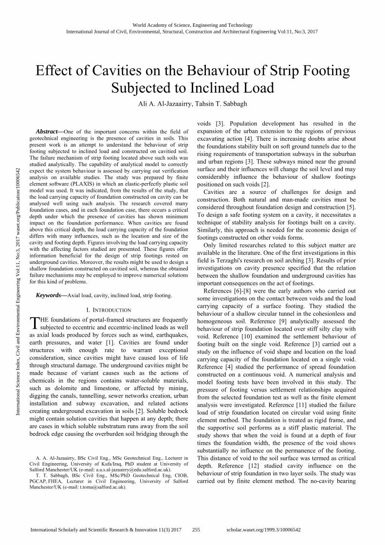
Effect of cavities on the behaviour of strip footing subjected to inclined load
AlJazaairry, AA and TomaSabbagh, TM
Title Effect of cavities on the behaviour of strip footing subjected to inclined load
Authors AlJazaairry, AA and TomaSabbagh, TM
Type Article
URL This version is available at: http://usir.salford.ac.uk/43501/
Published Date 2017
USIR is a digital collection of the research output of the University of Salford. Where copyright permits, full text material held in the repository is made freely available online and can be read, downloaded and copied for noncommercial private study or research purposes. Please check the manuscript for any further copyright restrictions.
For more information, including our policy and submission procedure, pleasecontact the Repository Team at: [email protected].
Abstract—One of the important concerns within the field of
geotechnical engineering is the presence of cavities in soils. This present work is an attempt to understand the behaviour of strip footing subjected to inclined load and constructed on cavitied soil. The failure mechanism of strip footing located above such soils was studied analytically. The capability of analytical model to correctly expect the system behaviour is assessed by carrying out verification analysis on available studies. The study was prepared by finite element software (PLAXIS) in which an elastic-perfectly plastic soil model was used. It was indicated, from the results of the study, that the load carrying capacity of foundation constructed on cavity can be analysed well using such analysis. The research covered many foundation cases, and in each foundation case, there occurs a critical depth under which the presence of cavities has shown minimum impact on the foundation performance. When cavities are found above this critical depth, the load carrying capacity of the foundation differs with many influences, such as the location and size of the cavity and footing depth. Figures involving the load carrying capacity with the affecting factors studied are presented. These figures offer information beneficial for the design of strip footings rested on underground cavities. Moreover, the results might be used to design a shallow foundation constructed on cavitied soil, whereas the obtained failure mechanisms may be employed to improve numerical solutions for this kind of problems.
Keywords—Axial load, cavity, inclined load, strip footing.
I. INTRODUCTION
HE foundations of portal-framed structures are frequently subjected to eccentric and eccentric-inclined loads as well
as axial loads produced by forces such as wind, earthquakes, earth pressures, and water [1]. Cavities are found under structures with enough rate to warrant exceptional consideration, since cavities might have caused loss of life through structural damage. The underground cavities might be made because of variant causes such as the actions of chemicals in the regions contains water-soluble materials, such as dolomite and limestone, or affected by mining, digging the canals, tunnelling, sewer networks creation, urban installation and subway excavation, and related actions creating underground excavation in soils [2]. Soluble bedrock might contain solution cavities that happen at any depth; there are cases in which soluble substratum runs away from the soil bedrock edge causing the overburden soil bridging through the
A. A. Al-Jazaairry, BSc Civil Eng., MSc Geotechnical Eng., Lecturer in Civil Engineering, University of Kufa/Iraq, PhD student at University of Salford Manchester/UK (e-mail: [email protected]).
T. T. Sabbagh, BSc Civil Eng., MSc/PhD Geotechnical Eng, CIOB, PGCAP, FHEA, Lecturer in Civil Engineering, University of Salford Manchester/UK (e-mail: [email protected]).
voids [3]. Population development has resulted in the expansion of the urban extension to the regions of previous excavating action [4]. There is increasing doubts arise about the foundations stability built on soft ground tunnels due to the rising requirements of transportation subways in the suburban and urban regions [3]. These subways mined near the ground surface and their influences will change the soil level and may considerably influence the behaviour of shallow footings positioned on such voids [2].
Cavities are a source of challenges for design and construction. Both natural and man-made cavities must be considered throughout foundation design and construction [5]. To design a safe footing system on a cavity, it necessitates a technique of stability analysis for footings built on a cavity. Similarly, this approach is needed for the economic design of footings constructed on other voids forms.
Only limited researches related to this subject matter are available in the literature. One of the first investigations in this field is Terzaghi's research on soil arching [3]. Results of prior investigations on cavity presence specified that the relation between the shallow foundation and underground cavities has important consequences on the act of footings.
References [6]-[8] were the early authors who carried out some investigations on the contact between voids and the load carrying capacity of a surface footing. They studied the behaviour of a shallow circular tunnel in the cohesionless and homogeneous soil. Reference [9] analytically assessed the behaviour of strip foundation located over stiff silty clay with void. Reference [10] examined the settlement behaviour of footing built on the single void. Reference [3] carried out a study on the influence of void shape and location on the load carrying capacity of the foundation located on a single void. Reference [4] studied the performance of spread foundation constructed on a continuous void. A numerical analysis and model footing tests have been involved in this study. The pressure of footing versus settlement relationships acquired from the selected foundation test as well as the finite element analysis were investigated. Reference [11] studied the failure load of strip foundation located on circular void using finite element method. The foundation is treated as rigid frame, and the supportive soil performs as a stiff plastic material. The study shows that when the void is found at a depth of four times the foundation width, the presence of the void shows substantially no influence on the permanence of the footing. This distance of void to the soil surface was termed as critical depth. Reference [12] studied cavity influence on the behaviour of strip foundation in two layer soils. The study was carried out by finite element method. The no-cavity bearing
Ali A. Al-Jazaairry, Tahsin T. Sabbagh
Effect of Cavities on the Behaviour of Strip Footing Subjected to Inclined Load
T
World Academy of Science, Engineering and TechnologyInternational Journal of Civil, Environmental, Structural, Construction and Architectural Engineering Vol:11, No:3, 2017
255International Scholarly and Scientific Research & Innovation 11(3) 2017 scholar.waset.org/1999.3/10006542
Inte
rnat
iona
l Sci
ence
Ind
ex, C
ivil
and
Env
iron
men
tal E
ngin
eeri
ng V
ol:1
1, N
o:3,
201
7 w
aset
.org
/Pub
licat
ion/
1000
6542
capacity value was used to obtain the reduction factor for each condition by dividing the with-cavity value by the no-cavity value. Reference [13] conducted an analytical investigation on the behaviour of a shallow foundation on covered underground tunnel in variant soils. It has been concentrated on the influence of dimension and position of concrete lining rigidity and void on the load carrying capacity of surface footing. A critical depth has been presented in which the void has negligible influences on the ultimate bearing capacity of the foundation.
Reference [14] conducted experimental tests to find the influence of water on the behaviour of strip footing above a cavity. It has been found that the most dangerous state regarding the stability of the footing is the case where the ground water rises gradually upward. The influence of various square-formed voids on the ultimate pressure of strip foundation has been assessed by [15] by retaining the profile of the foundation and void constant, whereas four various patterns for the voids location are presumed. Reference [16] conducted an experimental investigation on the load carrying capacity of foundation subjected to eccentric load. Foundations of variant shape and size have been studied. A good agreement was found between the test data and the theory. Reference [1] used artificial neural networks (ANNs) and a multi-linear regression model to estimate the ultimate loads of eccentric and eccentric-inclined loaded strip footings. The obtained experimental results proved that the load eccentricity, the soil density, and the load inclination had a significant influence on the load of the strip footings. Reference [2] examined the failure mechanism and load carrying capacity of strip foundation created on two voids. The results revealed that a critical distance between voids and a critical depth of them exist in which the effect on the load carrying capacity of foundation vanishes.
The influence of the location and size of the cavity on the performance of strip footing subjected to inclined load has not been well covered yet in the available literature. Therefore, this paper concentrated on investigating the load carrying capacity of the strip footing-cavity system for different cavity sizes, locations, and load inclinations. This study is limited to strip footings constructed on soils with continuous cavities of uniform shape and subjected to axial and inclined loading.
II. NUMERICAL ANALYSIS
The footing-soil-cavity system was simulated using the finite element software PLAXIS 2D. Mohr–Coulomb failure criterion was considered to simulate the behaviour of soils numerically. Since this work generally concentrates on the load carrying capacity of strip footing, an elastic perfectly plastic behaviour of the model is thought to be adequate. In all tests implemented in this analysis, it is supposed that an entirely stiff and rough strip footing is found on the soil surface without embedment depth. Furthermore, the dilatancy angle is presumed to be zero in all cases, since the friction angles are noticeably less than 30° [17]. Furthermore, the voids are supposed to have no lining. The boundaries from the axis of void must be increased about three to five times of the
cavity diameter. Thus, the horizontal and vertical limits of the model are selected appropriately far to avoid any influence on the outcomes. This was considered correct according to [18] and [13].
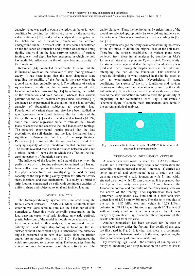
The system was geo-statically evaluated assuming no cavity in the soil mass, to define the original case of the soil mass. Therefore, the stresses established in variant plans were achieved from these initial analyses by considering Jaky's formula of lateral earth pressure Ko = 1 - sinϕ. Consequently, the stresses were regenerated in the system, while cavity was produced. Then, zeroing the displacements in the nodes and attempting the load on the foundation. This scenario is precisely simulating to what occurred in the in-site cases as well as experimental models. Nevertheless, in some conditions, the system of the strip foundation and cavities becomes unstable, and the calculation is paused by the code automatically. It has been created a local mesh modification around the strip foundation in order to avert the possibility of singularity at the foundation’s ends. Fig. 1 illustrates a schematic figure of suitable mesh arrangement considered in the current analytical analyses.
Fig. 1 Schematic finite element mesh (PLAXIS 2D) for numerical analyses in the present study
III. VERIFICATION OF FINITE ELEMENT SOFTWARE
A comparison was made between the PLAXIS software results and a relevant case study results for verification the capability of the numerical method. Reference [4] carried out some numerical and experimental tests to study the load carrying capacity of a strip foundation with 51 mm width situated on a void with 122 mm diameter. It is presumed that the top of the cavity was placed 102 mm beneath the foundation bottom, and the centre of the cavity was just below the centre of the footing. The experimental tests were performed using kaolin clay kind soil in a stiff tank with dimensions of 1524 mm by 366 mm. The elasticity modulus of the soil is 19.87 MPa, wet unit weight is 16.28 kN/m3, cohesion is 158.7 kPa, and friction angle equals 8°. The test of without cavity condition which is conducted by [4] was analytically simulated. Fig. 2 revealed the comparison of the results obtained from this case.
Another comparison has been achieved for the case of presence of cavity under the footing. The details of this case are illustrated in Fig. 3. It is clear that there is a commonly good agreement between results in both cases, representing the ability and accuracy of numerical modelling.
By reviewing Figs. 2 and 3, the accuracy of assumptions in analytical modelling of a strip foundation on a cavitied soil is
World Academy of Science, Engineering and TechnologyInternational Journal of Civil, Environmental, Structural, Construction and Architectural Engineering Vol:11, No:3, 2017
256International Scholarly and Scientific Research & Innovation 11(3) 2017 scholar.waset.org/1999.3/10006542
Inte
rnat
iona
l Sci
ence
Ind
ex, C
ivil
and
Env
iron
men
tal E
ngin
eeri
ng V
ol:1
1, N
o:3,
201
7 w
aset
.org
/Pub
licat
ion/
1000
6542

acceptable, and thus, it can be expanded to study the influence of cavity presence on the load carrying capacity of strip foundations located on such soil.
Fig. 2 Present finite element results and Badie and Wang’s results comparison in the case of no cavity
Fig. 3 Present finite element results and Badie and Wang’s results [4] comparison in the case of cavity presence
IV. PARAMETRIC STUDY
Two soil failure modes may arise in the presence of cavities below a single shallow footing. The ultimate bearing pressure is considered as the average vertical stress produced at Gauss points underneath the foundation when one of the failure modes is encountered either by controlling the shear band’s shape or the stability of the model [2]. a. The cavity becomes unbalanced before creating the
mechanism of shear failure under the footing. In this case, the stress generated beneath the foundation is designated as the load carrying capacity of the foundation.
b. When the failure mechanism approaches the ground surface, the general shear failure occurs.
At different stages of analysis, the analytical results showed that the dramatic difference in the slope of load-settlement curve leads to instability in the structure, whereas in the situation of general shear failure, the slope of load-
deformation curve was varied steadily. Consequently, the load carrying capacity is determined as the stress at the point of maximum curvature in load-deformation curve where the types of failure mentioned above can be matched. Fig. 4 shows the schematic sketch of the generally potential failure types for a strip foundation built on soil mass with a single cavity.
A parametric study has been conducted, in this section, to explore the influence of cavities location and size on the load carrying capacity of the shallow foundation subjected to an axial and oblique loading.
Fig. 4 Schematic outline of potential mechanisms of failure in footing-cavity system. (a) Instability in cavity walls. (b) General
shear failure [2]
In this study, the physical properties of the selected soil are as follow: modulus of elasticity E = 15000 kN/m2, cohesion c = 65 kN/m2, friction angle ϕ = 15°, dry unit weight γd = 16 kN/m3, and Poisson’s ratio υ = 0.28.
Fig. 5 shows the strip foundation geometry constructed on the soil with circular cavity and the parameters such as footing width (B), load inclination (i), cavity diameter (D), depth of cavity top from the bottom of the footing (Z), and the horizontal distance of cavity centreline to the footing centre. A dimensionless parameter (qc/qn) which has been defined is the bearing pressure ratio to investigate the difference of bearing pressure, where qc denotes the bearing pressure of shallow foundation with the presence of cavity and qn represents ultimate bearing capacity for no cavity condition. Therefore, the bearing pressure ratio (qc/qn) for without cavity state tends to 1, whereas the present bearing pressure at final load is equivalent to load carrying capacity. To make fair comparisons between the numerical tests, the geometric forms are presented in terms of the following dimensionless parameters: (s/B): footing settlement to footing width. (D/B): cavity diameter to footing width, D/B = 0.5, 1, and
2. (Z/B): cavity depth from the footing base to footing width,
Z/B = 1, 2, and 3. (X/B): cavity horizontal distance from footing centreline
to footing width, X/B = 0, 1, and 2.
A. Effect of Cavity Size
Fig. 6 shows the pressure-displacement variants as dimensionless ratios of a strip foundation of 1.5 m width which is situated on the cavity with various diameters. The load inclination (i) is varied from 0° to 30°. It is to be mentioned that the crowns of cavities are located at the same depth as of the footing base, i.e. Z is constant. Figs. 6 (a)-(c) show that by increasing the diameter of the cavity, the bearing
World Academy of Science, Engineering and TechnologyInternational Journal of Civil, Environmental, Structural, Construction and Architectural Engineering Vol:11, No:3, 2017
257International Scholarly and Scientific Research & Innovation 11(3) 2017 scholar.waset.org/1999.3/10006542
Inte
rnat
iona
l Sci
ence
Ind
ex, C
ivil
and
Env
iron
men
tal E
ngin
eeri
ng V
ol:1
1, N
o:3,
201
7 w
aset
.org
/Pub
licat
ion/
1000
6542
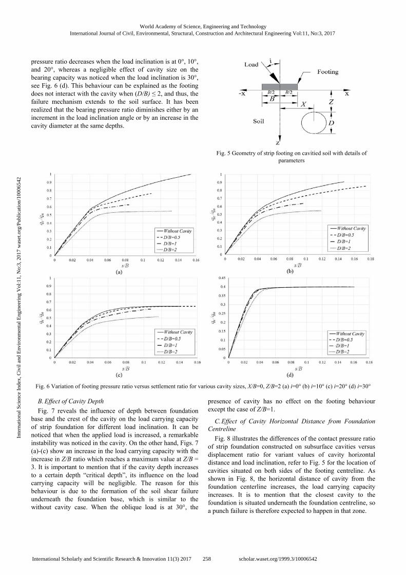
pressure ratio decreases when the load inclination is at 0°, 10°, and 20°, whereas a negligible effect of cavity size on the bearing capacity was noticed when the load inclination is 30°, see Fig. 6 (d). This behaviour can be explained as the footing does not interact with the cavity when (D/B) ≤ 2, and thus, the failure mechanism extends to the soil surface. It has been realized that the bearing pressure ratio diminishes either by an increment in the load inclination angle or by an increase in the cavity diameter at the same depths.
Fig. 5 Geometry of strip footing on cavitied soil with details of parameters
Fig. 6 Variation of footing pressure ratio versus settlement ratio for various cavity sizes, X/B=0, Z/B=2 (a) i=0° (b) i=10° (c) i=20° (d) i=30° B. Effect of Cavity Depth
Fig. 7 reveals the influence of depth between foundation base and the crest of the cavity on the load carrying capacity of strip foundation for different load inclination. It can be noticed that when the applied load is increased, a remarkable instability was noticed in the cavity. On the other hand, Figs. 7 (a)-(c) show an increase in the load carrying capacity with the increase in Z/B ratio which reaches a maximum value at Z/B = 3. It is important to mention that if the cavity depth increases to a certain depth “critical depth”, its influence on the load carrying capacity will be negligible. The reason for this behaviour is due to the formation of the soil shear failure underneath the foundation base, which is similar to the without cavity case. When the oblique load is at 30°, the
presence of cavity has no effect on the footing behaviour except the case of Z/B=1.
C. Effect of Cavity Horizontal Distance from Foundation Centreline
Fig. 8 illustrates the differences of the contact pressure ratio of strip foundation constructed on subsurface cavities versus displacement ratio for variant values of cavity horizontal distance and load inclination, refer to Fig. 5 for the location of cavities situated on both sides of the footing centreline. As shown in Fig. 8, the horizontal distance of cavity from the foundation centerline increases, the load carrying capacity increases. It is to mention that the closest cavity to the foundation is situated underneath the foundation centreline, so a punch failure is therefore expected to happen in that zone.
World Academy of Science, Engineering and TechnologyInternational Journal of Civil, Environmental, Structural, Construction and Architectural Engineering Vol:11, No:3, 2017
258International Scholarly and Scientific Research & Innovation 11(3) 2017 scholar.waset.org/1999.3/10006542
Inte
rnat
iona
l Sci
ence
Ind
ex, C
ivil
and
Env
iron
men
tal E
ngin
eeri
ng V
ol:1
1, N
o:3,
201
7 w
aset
.org
/Pub
licat
ion/
1000
6542
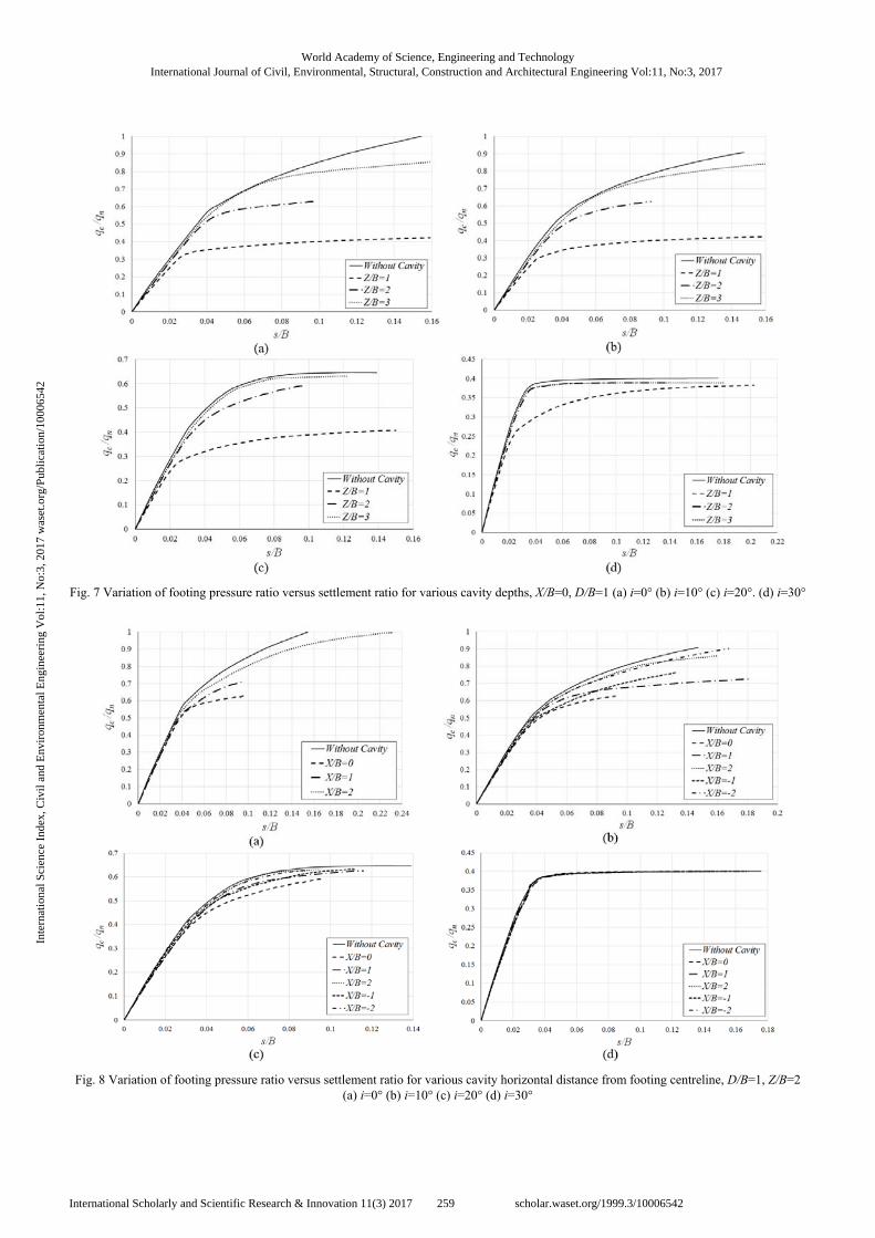
Fig. 7 Variation of footing pressure ratio versus settlement ratio for various cavity depths, X/B=0, D/B=1 (a) i=0° (b) i=10° (c) i=20°. (d) i=30°
Fig. 8 Variation of footing pressure ratio versus settlement ratio for various cavity horizontal distance from footing centreline, D/B=1, Z/B=2 (a) i=0° (b) i=10° (c) i=20° (d) i=30°
World Academy of Science, Engineering and TechnologyInternational Journal of Civil, Environmental, Structural, Construction and Architectural Engineering Vol:11, No:3, 2017
259International Scholarly and Scientific Research & Innovation 11(3) 2017 scholar.waset.org/1999.3/10006542
Inte
rnat
iona
l Sci
ence
Ind
ex, C
ivil
and
Env
iron
men
tal E
ngin
eeri
ng V
ol:1
1, N
o:3,
201
7 w
aset
.org
/Pub
licat
ion/
1000
6542
V. CRITICAL VALUES FOR DESIGN RECOMMENDATIONS
In order to account for the effect of all the parameters involved in this study, such as D/B, Z/B, and X/B, a Reduction Factor (RF) has been introduced as:
Reduction Factor= qn - qc
qn
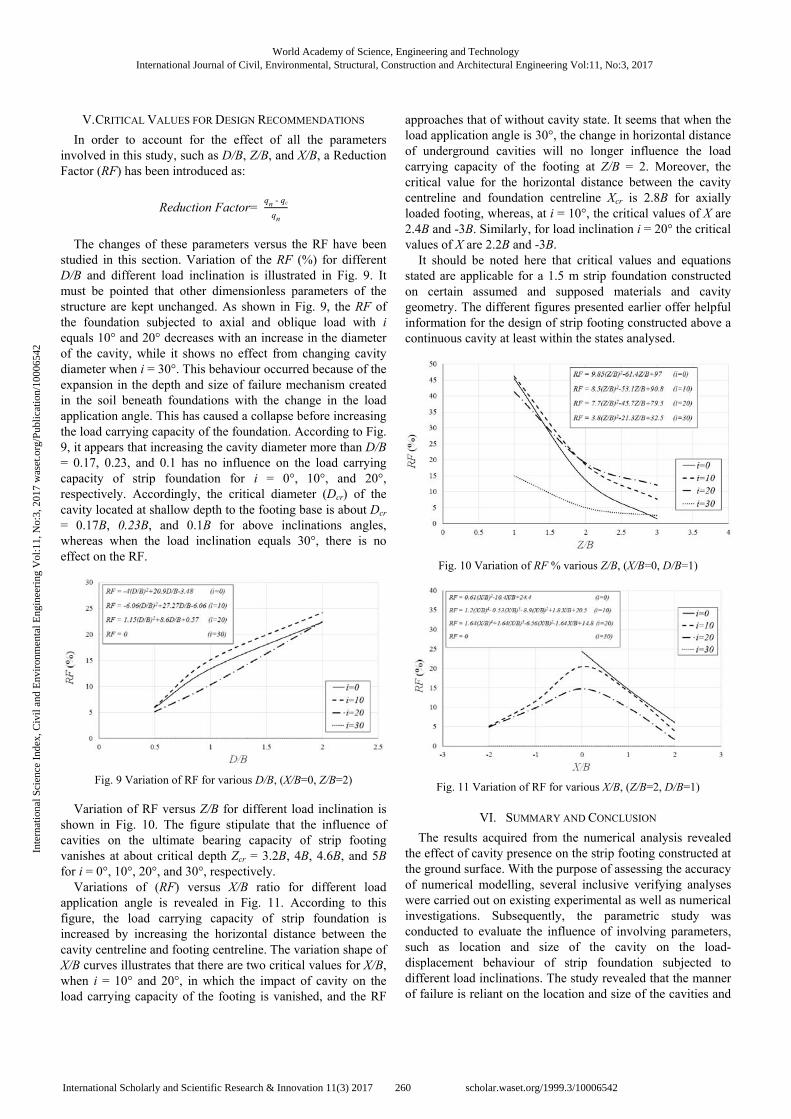
The changes of these parameters versus the RF have been
studied in this section. Variation of the RF (%) for different D/B and different load inclination is illustrated in Fig. 9. It must be pointed that other dimensionless parameters of the structure are kept unchanged. As shown in Fig. 9, the RF of the foundation subjected to axial and oblique load with i equals 10° and 20° decreases with an increase in the diameter of the cavity, while it shows no effect from changing cavity diameter when i = 30°. This behaviour occurred because of the expansion in the depth and size of failure mechanism created in the soil beneath foundations with the change in the load application angle. This has caused a collapse before increasing the load carrying capacity of the foundation. According to Fig. 9, it appears that increasing the cavity diameter more than D/B = 0.17, 0.23, and 0.1 has no influence on the load carrying capacity of strip foundation for i = 0°, 10°, and 20°, respectively. Accordingly, the critical diameter (Dcr) of the cavity located at shallow depth to the footing base is about Dcr = 0.17B, 0.23B, and 0.1B for above inclinations angles, whereas when the load inclination equals 30°, there is no effect on the RF.
Fig. 9 Variation of RF for various D/B, (X/B=0, Z/B=2)
Variation of RF versus Z/B for different load inclination is shown in Fig. 10. The figure stipulate that the influence of cavities on the ultimate bearing capacity of strip footing vanishes at about critical depth Zcr = 3.2B, 4B, 4.6B, and 5B for i = 0°, 10°, 20°, and 30°, respectively.
Variations of (RF) versus X/B ratio for different load application angle is revealed in Fig. 11. According to this figure, the load carrying capacity of strip foundation is increased by increasing the horizontal distance between the cavity centreline and footing centreline. The variation shape of X/B curves illustrates that there are two critical values for X/B, when i = 10° and 20°, in which the impact of cavity on the load carrying capacity of the footing is vanished, and the RF
approaches that of without cavity state. It seems that when the load application angle is 30°, the change in horizontal distance of underground cavities will no longer influence the load carrying capacity of the footing at Z/B = 2. Moreover, the critical value for the horizontal distance between the cavity centreline and foundation centreline Xcr is 2.8B for axially loaded footing, whereas, at i = 10°, the critical values of X are 2.4B and -3B. Similarly, for load inclination i = 20° the critical values of X are 2.2B and -3B.
It should be noted here that critical values and equations stated are applicable for a 1.5 m strip foundation constructed on certain assumed and supposed materials and cavity geometry. The different figures presented earlier offer helpful information for the design of strip footing constructed above a continuous cavity at least within the states analysed.
Fig. 10 Variation of RF % various Z/B, (X/B=0, D/B=1)
Fig. 11 Variation of RF for various X/B, (Z/B=2, D/B=1)
VI. SUMMARY AND CONCLUSION
The results acquired from the numerical analysis revealed the effect of cavity presence on the strip footing constructed at the ground surface. With the purpose of assessing the accuracy of numerical modelling, several inclusive verifying analyses were carried out on existing experimental as well as numerical investigations. Subsequently, the parametric study was conducted to evaluate the influence of involving parameters, such as location and size of the cavity on the load-displacement behaviour of strip foundation subjected to different load inclinations. The study revealed that the manner of failure is reliant on the location and size of the cavities and
World Academy of Science, Engineering and TechnologyInternational Journal of Civil, Environmental, Structural, Construction and Architectural Engineering Vol:11, No:3, 2017
260International Scholarly and Scientific Research & Innovation 11(3) 2017 scholar.waset.org/1999.3/10006542
Inte
rnat
iona
l Sci
ence
Ind
ex, C
ivil
and
Env
iron
men
tal E
ngin
eeri
ng V
ol:1
1, N
o:3,
201
7 w
aset
.org
/Pub
licat
ion/
1000
6542
in addition the load inclination angle. Below are the conclusions drawn from the results of this study: 1. Presence of cavities underneath a strip footing creates a
reduction in the load carrying capacity depending on the location and size of the cavity.
2. Increasing the cavity diameter leads to a noticeable decrease in the load carrying capacity of the foundation with the depth of cavity crown to the footing base kept unchanged.
3. Based on the numerical results, an increase in the depth of cavities beyond Zcr = 5B, the load carrying capacity of the strip foundation constructed on the cavities remained constant.
4. The influence of the cavity position in the horizontal distance on the behaviour of strip footing X/B ≥ 2.4 and -3 can be neglected when the D/B =1 and Z/B = 2.
5. With different X/B ratios, there is no effect of the cavity on the strip footing when the load inclination angle increases to 30° at dimensionless factors D/B =1 and Z/B = 2.
REFERENCES [1] M. Ornek, Estimation of ultimate loads of eccentric-inclined loaded strip
footings rested on sandy soils. Neural Computing & Applications, 2014. 25(1): p. 39-54.
[2] A. A. Lavasan, A. Talsaz, M. Ghazavi, and T. Schanz, Behavior of Shallow Strip Footing on Twin Voids. Geotechnical and Geological Engineering, 2016: p. 1-15.
[3] R. L. Baus, and M. C. Wang, Bearing Capacity of Strip Footing above Void. Journal of Geotechnical Engineering-Asce, 1983. 109(1): p. 1-14.
[4] A. Badie, and M. C. Wang, Stability of Spread Footing above Void in Clay. Journal of Geotechnical Engineering-Asce, 1984. 110(11): p. 1591-1605.
[5] D. K. Crapps, The Effects of Cavities upon Foundation Design & Construction. in Art of Foundation Engineering Practice. 2010. ASCE.
[6] J. H. Atkinson, and A. M. Cairncross. Collapse of a shallow tunnel in a Mohr-Coulomb material. in Proceedings of the Symposium on the Role of Plasticity in Soil Mechanics, Cambridge, UK. 1973.
[7] J. H. Atkinson, E. T. Brown, and D.M. Potts, Collapse of shallow unlined tunnels in dense sand. Tunnels and Tunneling, 1975. 7(3): p. 81-87.
[8] J. H. Atkinson, and D. M. Potts, Stability of a Shallow Circular Tunnel in Cohesionless Soil. Geotechnique, 1977. 27(2): p. 203-215.
[9] R. L. Baus, The stability of shallow continuous footings located above voids. 1978, Pennsylvania State University, at University Park, Pennsylvania, USA.
[10] M. C. Wang, and R. L. Baus. Settlement behavior of footing above a void. in Proceedings of the 2nd conference on ground movement and structures. Cardiff, UK. 1980.
[11] M. C. Wang, and C.W. Hsieh, Collapse Load of Strip Footing above Circular Void. Journal of Geotechnical Engineering-Asce, 1987. 113(5): p. 511-515.
[12] G. Azam, M. Jao, and M. C. Wang, Cavity effect on stability of strip footing in two-layer soils. Geotechnical Engineering, 1997. 28(2).
[13] M. Jao, and M. C. Wang, Stability of strip footings above concrete-lined soft ground tunnels. Tunnelling and Underground Space Technology, 1998. 13(4): p. 427-434.
[14] L. J. Aziz, Influence of water on the behavior of strip footing above a cavity, in Department of Building and Construction Engineering. 2002, University of Technology/Iraq.
[15] M. Kiyosumi, O. Kusakabe, M. Ohuchi, and F. Le Peng, Yielding pressure of spread footing above multiple voids. Journal of Geotechnical and Geoenvironmental Engineering, 2007. 133(12): p. 1522-1531.
[16] S. M. Nawghare, S. R. Pathak, and S. H. Gawande, Experimental investigations of bearing capacity for eccentrically loaded footing. Int J Eng Sci Technol, 2010. 2(10): p. 5257-5264.
[17] M. D. Bolton, The strength and dilatancy of sands. Geotechnique 1986. 36(1): p. 65-78.
[18] M. C. Wang, and A. Badie, Effect of Underground Void on Foundation Stability. Journal of Geotechnical Engineering-Asce, 1985. 111(8): p. 1008-1019.
World Academy of Science, Engineering and TechnologyInternational Journal of Civil, Environmental, Structural, Construction and Architectural Engineering Vol:11, No:3, 2017
261International Scholarly and Scientific Research & Innovation 11(3) 2017 scholar.waset.org/1999.3/10006542
Inte
rnat
iona
l Sci
ence
Ind
ex, C
ivil
and
Env
iron
men
tal E
ngin
eeri
ng V
ol:1
1, N
o:3,
201
7 w
aset
.org
/Pub
licat
ion/
1000
6542