Embed Size (px)
Citation preview
EFFECT OF COMMERCIAL AND MILITARY PERFORMANCE REQUIREMENTS FOR TRANSPORT CATEGORY AIRCRAFT ON SPACE SHUTTLE BOOSTER DESIGN AND OPERATION
R. A. Bithell and W. A. Pence, Jr. Convair Aerospace Division of General Dynamics
San Diego, California
https://ntrs.nasa.gov/search.jsp?R=19720013237 2018-06-25T17:48:42+00:00Z
INTRODUCTION
E
The operating rules under which an aircraft performs affect every phase of flight from takeoff to landing and help determine engine requirements by setting critical thrust levels for various flight modes. The effect of two such sets of performance requirements, commercial and military, on the design and operation of the Space Shuttle booster is evaluated according to the following documents: Part 25 and Part 121 of the Federal Aviation Regulations (FAR) for commercial transport category aircraft; and MIL-C-5011A performance requirements for military aircraft.
Critical thrust levels are established according to both sets of operating rules for the takeoff, cruise, and go-around flight modes, and the effect on engine requirements determined. Both flyback and ferry operations are considered. The impact of landing rules on potential shuttle flyback and ferry bases is evaluated. Factors affecting reserves are discussed, including winds, temperature, and nonstandard flight operations. Finally, a recommended set of operating rules is proposed for both flyback and ferry operations that allows adequate performance capability and safety margins without compromising. design requirements for either flight phase.
INTRODUCTION
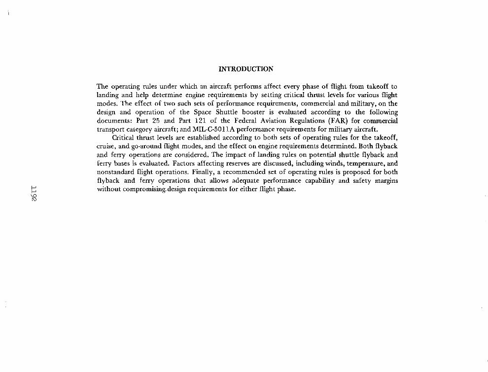
FLYBACK PERFORMANCE
CRUISE GO-AROUND
LAND I NG RULES RESERVES
THRUST ,REQU I REMENTS
ATMOSP HE RE W I NDS ENG I NE-OUT GO-AROUND
RECOMMENDED OPERATING RULES
FERRY OPERATIONS FERRY ROUTES THRUST REQU I REMENTS
CRUISE GO-AROUND TAKEOFF
LAND I NG PERFORMANCE RESERVES RECOMMENDED OPERATING RULES
BOOSTER CONFIGURATION
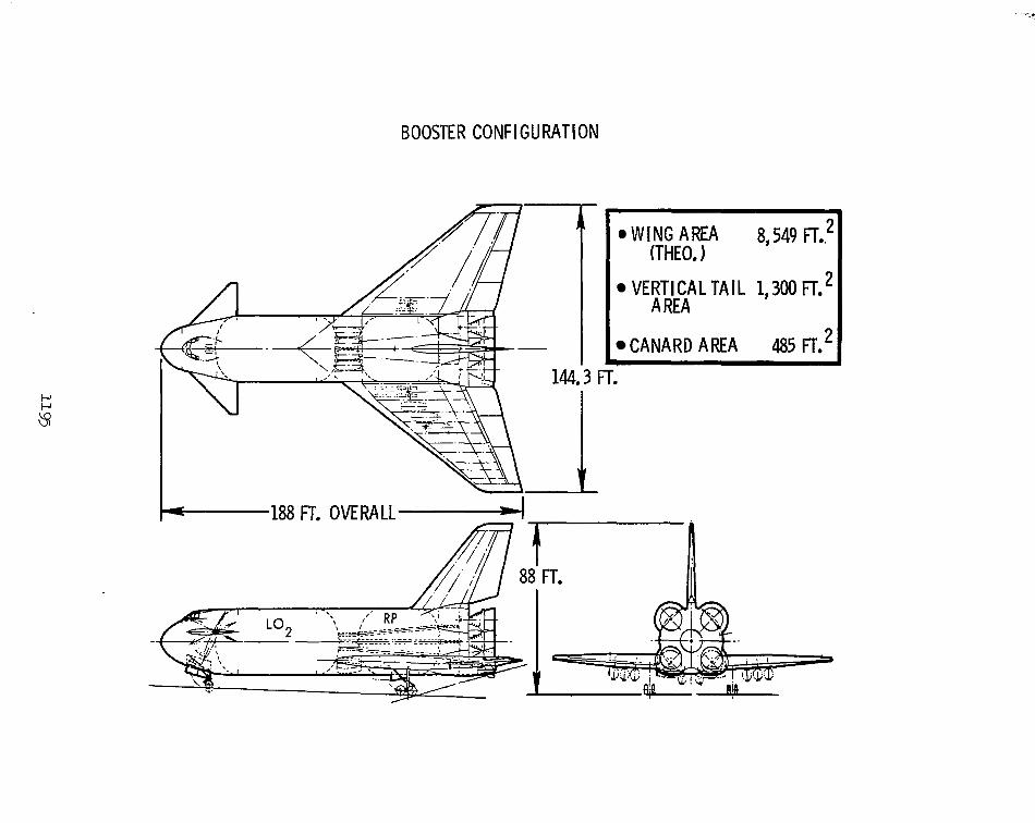
Configuration geometry for a representative Space Shuttle booster is presented. The vehicle shown is an L02/RP booster with delta wing/canard geometry. The flyback engines are low bypass ratio turbofans burning JP-5; they are installed within the wing and deploy beneath it while in operation.
Details of the booster performance are based on this configuration.
BOOSTER CONFIGURATION
W I N G AREA 8,549 FT.? VERTICAL TAIL 1,3OO F L 2
CANARD AREA 485 Re2
(THEO. 1
A REA
CANDIDATE LANDING SITES
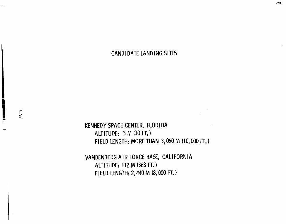
Two landing sites for the baseline configuration are considered for flyback because of their current launch vehicle capability: Kennedy Space Center, Florida, and Vandenberg Air Force Base, California. The elevation for both locations is near sea level.
At the present time, no landing facility exists at KSC, but field lengths over 3,050 meters (10,000 feet) are being planned. The 2,440-meter (8,000-foot) runway at Vandenberg may not be adequate to accommodate booster landings at heavy gross weights under wet field conditions, and extension of the runway may have to be considered.
CANDIDATE LANDING SITES
KENNEDY SPACE CENTER, FLORIDA ALTITUDE: 3 M (10 FT.1 FIELD LENGTH: MORE THAN 3,050 M (10,000 FT.)
VANDENBERG A I R FORCE BASE, CALIFORNIA ALTITUDE: 112 M (368 FT.) FIELD LENGTH: 2,440 M (8,000 FT.
CRUISE OPTIMIZATION
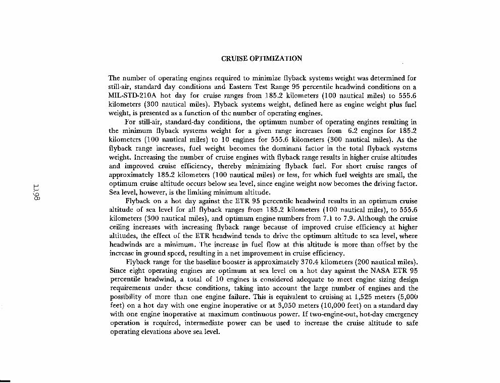
The number of operating engines required to minimize flyback systems weight was determined for still-air, standard day conditions and Eastern Test Range 95 percentile headwind conditions on a MIL-STD-210A hot day for cruise ranges from 185.2 kilometers (100 nautical miles) to 555.6 kilometers (300 nautical miles). Flyback systems weight, defined here as engine weight plus fuel weight, is presented as a function of the number of operating engines.
For still-air, standard-day conditions, the optimum number of operating engines resulting in the minimum flyback systems weight for a given range increases from 6.2 engines for 185.2 kilometers (100 nautical miles) to 10 engines for 555.6 kilometers (300 nautical miles). As the flyback range increases, fuel weight becomes the dominant factor in the total flyback systems weight. Increasing the number of cruise engines with flyback range results in higher cruise altitudes and improved cruise efficiency, thereby minimizing flyback fuel. For short cruise ranges of approximately 185.2 kilometers (100 nautical miles) or less, for which fuel weights are small, the optimum cruise altitude occurs below sea level, since engine weight now becomes the driving factor. Sea level, however, is the limiting minimum altitude.
Flyback on a hot day against the ETR 95 percentile headwind results in an optimum cruise altitude of sea level for all flyback ranges from 185.2 kilometers (100 nautical miles), to 555.6 kilometers (300 nautical miles), and optimum engine numbers from 7.1 to 7.9. Although the cruise ceiling increases with increasing flyback range because of improved cruise efficiency at higher altitudes, the effect of the ETR headwind tends to drive the optimum altitude to sea level, where headwinds are a minimum. The increase in fuel flow at this altitude is more than offset by the increase in ground speed, resulting in a net improvement in cruise efficiency.
Flyback range for the baseline booster is approximately 370.4 kilometers (200 nautical miles). Since eight operating engines are optimum at sea level on a hot day against the NASA ETR 95 percentile headwind, a total of 10 engines is considered adequate to meet engine sizing design requirements under these conditions, taking into account the large number of engines and the possibility of more than one engine failure. This is equivalent to cruising at 1,525 meters (5,000 feet) on a hot day with one engine inoperative or at 3,050 meters (10,000 feet) on a standard day with one engine inoperative at maximum continuous power. If two-engine-out, hot-day emergency operation is required, intermediate power can be used to increase the cruise altitude to safe operating elevations above sea level.
CRUISE O P T I M I Z A T I O N
$0.40
GO. 30
>: 0.20
0
G:
STILL A I R STANDARD DAY
1 4 0 p
120 -
185 KM 1100 N.MI.1
-"6 7 8 9 10 11 12 NO. OPERATING ENG I NES
0.
I *I 0. h z "0 0. d 1
0.
0.
60 140
40
30 Y
6
ETR 95 PERCENT1 LE WINDS 0 HOT DAY
185 KM ( 100 N.MI.
I I I I I 7 8 9 10 11 12
NO. OPERATING ENGINES
GO-AROUND CLIMB GRADIENTS
0 0
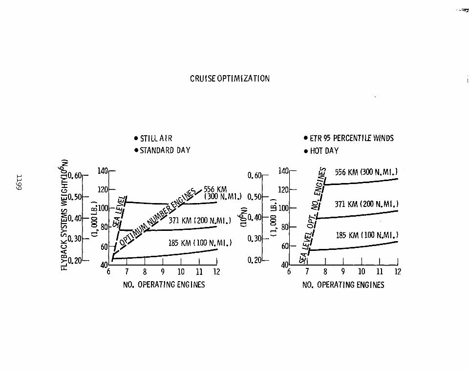
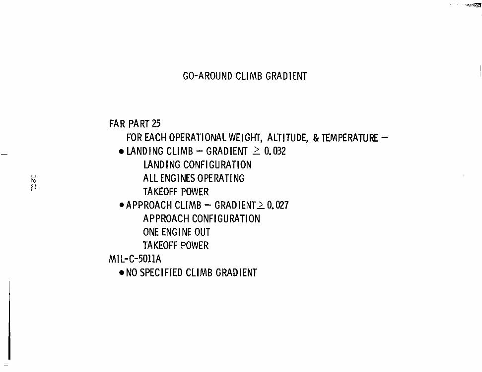
The commerical and military climb gradient requirements for the landing and approach configurations are presented. The Federal Aviation Regulations (FAR) Part 25 requires that compliance with specified climb gradients must be shown at each weight, altitude, and ambient temperature within the operational limits of the aircraft for both the landing and approach configurations. These configurations are generally selected by the applicant seeking certification. The approach configuration for the booster is defined by the approach canard setting (+lo degrees), with elevons set for trim and landing gear retracted. The landing configuration is defined by the landing canard setting (+15 degrees), with elevons set for trim and landing gear down and locked. In addition, the stall speed (vs), or minimum speed, for the approach configuration cannot exceed 11 0% of the stall speed for the related landing configuration.
Compliance with the climb gradients shown is required for four-engine aircraft with all engines operating in the landing configuration, or one engine out in the approach configuration. Climb gradients for turbine-engine-powered vehicles with more than four engines, such as Space Shuttle, are not specifically covered in FAR Part 25.
No specified climb gradient is required by MIL-CdOllA in the landing and approach configuration. However, climb performance must be calculated with all engines operating and one engine inoperative.
GO-AROUND CLIMB GRADIENT
FAR PART 25 FOR EACH OPERATIONAL WEIGHT, ALTITUDE, & TEMPERATURE - LANDING CLIMB - GRADIENT 2 0.032
LANDING CONFIGURATION ALL ENGINES OPERATING TA KEOFF POW E R
@APPROACH CLIMB - GRADIENT2 0.027 APPROACH CONFIGURATION ONE ENGl NE OUT TAKEOFF POWER
M I L- C-5011A NO SPECIFIED CLIMB GRADIENT
GO-AROUND THRUST REQUIREMENTS
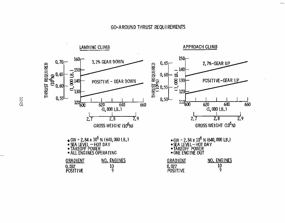
The thrust required to meet the FAR Part 25 landing and approach climb gradients is presented as a function of landing gross weight, together with that required to maintain a positive climb gradient. Engine requirements are determined for the critical hot-day conditions at sea level. In the landing configuration for a gross weight of 2.85 x 10⁶ N (640,000 pounds), with gear down and canard set at +15 degrees, 10 engines are required to maintain the FAR climb gradient of 0.032; nine engines are needed to maintain a positive gradient. In the approach configuration at the same gross weight, with gear up and canard set at +10 degrees, 10 engines are necessary to meet the required FAR climb gradient of 0.027, whereas nine are needed to maintain a positive gradient. All engines are operating in the landing configuration, with one engine inoperative for approach. Throttles are at takeoff power.
Because of the large number of engines required on the baseline booster, it is felt that allowance should be made for more inoperative engines than is required by Part 25 of the FAR. Increasing the number of inoperative engines from none to one for the landing configuration, and from one to two for the approach configuration, while maintaining a positive climb gradient, provides for safe operation in both flight modes. For the baseline configuration, this results in 10 flyback engines, or the same number required to maintain the FAR gradients.
Iu P
w 0
GO-AROUND THRUST REQU I REMENTS
LANDING CLIMB APPROACH CLIMB
120600 620 640 660 1
(1, OOO LB. 1 I I
2.7 2.8 2.9 GROSS WEIGHT (106N1
GW = 2.84 X lo6 N (640.W LB.) 0 SEA LEVEL -HOT DAY ' 0 TAKEOFF POWER 0 ALL ENGl NES OPERATING
GRADIENT NO. ENG I NES 0.032 10 POSITIVE 9
W POSITIVE-GEAR UP
E- - 120 I
+ 0 . 5 0 L I I I I I I I 110600 620 640 660
(1,000 LB. 1 u 2.7 2.8 2.9
GROSS WE1 GHT (106N)
0 GW = 2.84 X lo6 N (640, OOO LB.) O S E A LEVEL-HOT DAY '
.TAKEOFF POWER 0 ONE ENG I NE OUT
GRADIENT NO. ENGINES
POSITIVE 9 0.027 10
LANDING RULES
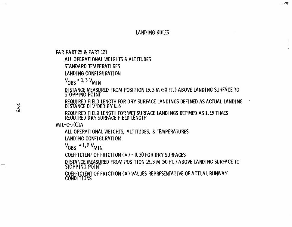
Landing rules according to the Federal Aviation Regulations and MIL-C-5011A are presented. Part 25 of the FAR includes the threshold speed requirements; Part 121 covers the stopping distance requirements for wet and dry field operation. Landing performance must be determined for each weight and altitude within the operational limits of the aircraft and for standard temperatures.
Landing performance according to MIL-C-501 1A must be determined for each operational weight, altitude, and temperature. The distances are not factored to determine required field length. However, coefficient of friction values must be representative of actual runway conditions.
LAND ING RULES
FAR PART 25 & PART 121 ALL OPERATIONAL WEIGHTS & ALTI' STANDARD TEMPERATURES LANDING CONFIGURATION
VOBS l e 3 VMIN DISTANCE MEASURED FROM POSIT1 STOPPING POINT
TU DES
ON 15.3 M (50 FT.) ABOVE LANDING SURFACE TO
REQUIRED FIELD LENGTH FOR DRY SURFACE LANDINGS DEFINED AS ACTUAL LANDING - DISTANCE D I V I D E D B Y 0.6 REQUIRED FIELD LENGTH FOR WET SURFACE LANDINGS DEFINED AS 1.15 TIMES REQUIRED DRY SURFACE FIELD LENGTH
ALL OPERATIONAL WEIGHTS, ALTITUDES, & TEMPERATURES LANDING CONFIGURATION
MI L-C-5011A
VOBS l.2 VMIN COEFFICIENT OF FRICTION ( P ) = 0.30 FOR DRY SURFACES DISTANCE MEASURED FROM POSITION 15.3 M (50 FT.) ABOVE LANDING SURFACE TO STOPPING POINT COEFFICIENT OF FRICTION ( P 1 VALUES REPRESENTATIVE OF ACTUAL RUNWAY CONDITIONS
I
I
LANDING PERFORMANCE
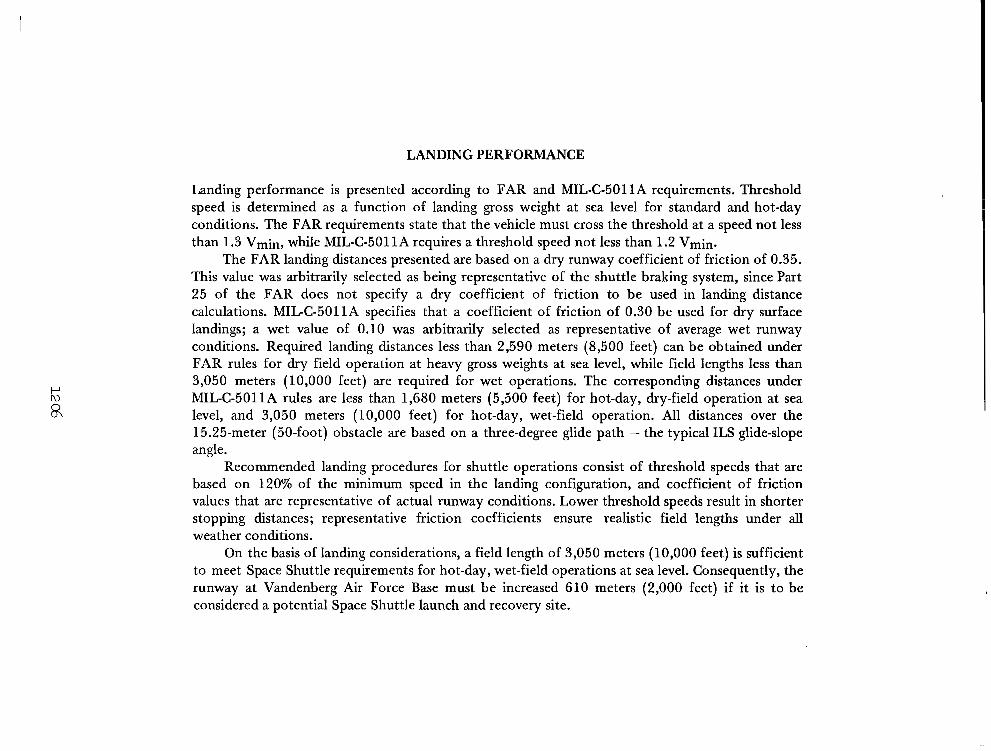
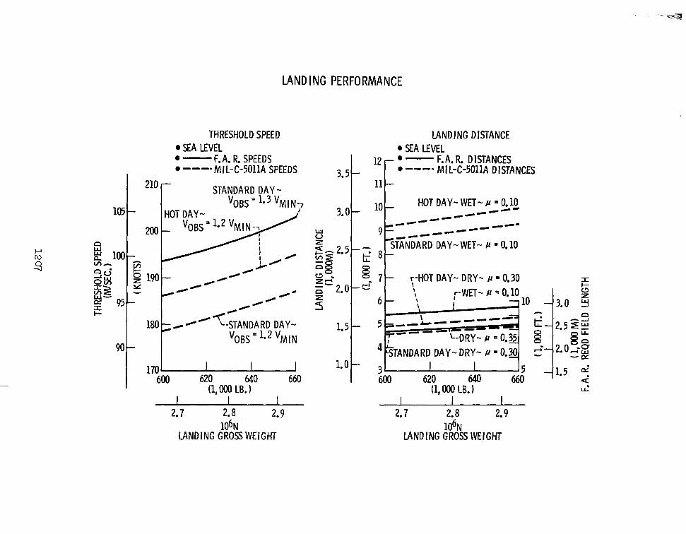
Landing performance is presented according to FAR and MIL-C-5011A requirements. Threshold speed is determined as a function of landing gross weight at sea level for standard and hot-day conditions. The FAR requirements state that the vehicle must cross the threshold at a speed not less than 1.3 Vmin, while MIL-C-5011A requires a threshold speed not less than 1.2 Vmin.
The FAR landing distances presented are based on a dry runway coefficient of friction of 0.35. This value was arbitrarily selected as being representative of the shuttle braking system, since Part 25 of the FAR does not specify a dry coefficient of friction to be used in landing distance calculations. MIL-C-5011A specifies that a coefficient of friction of 0.30 be used for dry surface landings; a wet value of 0.10 was arbitrarily selected as representative of average wet runway conditions. Required landing distances less than 2,590 meters (8,500 feet) can be obtained under FAR rules for dry field operation at heavy gross weights at sea level, while field lengths less than 3,050 meters (10,000 feet) are required for wet operations. The corresponding distances under MIL-C-5011A rules are less than 1,680 meters (5,500 feet) for hot-day, dry-field operation at sea level, and 3,050 meters (10,000 feet) for hot-day, wet-field operation. All distances over the 15.25-meter (50-foot) obstacle are based on a three-degree glide path - the typical ILS glide-slope angle.
Recommended landing procedures for shuttle operations consist of threshold speeds that are based on 120% of the minimum speed in the landing configuration, and coefficient of friction values that are representative of actual runway conditions. Lower threshold speeds result in shorter stopping distances; representative friction coefficients ensure realistic field lengths under all weather conditions.
On the basis of landing considerations, a field length of 3,050 meters (10,000 feet) is sufficient to meet Space Shuttle requirements for hot-day, wet-field operations at sea level. Consequently, the runway at Vandenberg Air Force Base must be increased 610 meters (2,000 feet) if it is to be considered a potential Space Shuttle launch and recovery site.
LANDING PERFORMANCE
210
105
200
I 180
THRESHOLD SPEED SEA LEVEL .- F. A. R. SPEEDS . ”-. MIL-C-5011A SPEEDS
90
17!00 620 640 660 (1, OOO LB. 1
I I 2.7 2.8 2.9
MNDING DISTANCE
F. A. R. DISTANCES . ”W. MIL-C5011A DISTANCES
3.0 I HOT DAY- WET- P = 0.10 ”- .-- ””
”e” ”e-
”-- STANDARD DAY - WET- P = 0.10
1.0 lo5I 3-5 600 620 640 660 4 1 . 5 e2 i
ul (1, OOO LB. 1 1
2.7 2.8 2.9 106N
LANDING GROSS WEIGHT lo6 N
LANDING GROSS WEIGHT
RESERVES
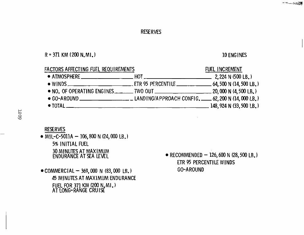
The various factors affecting fuel reserve requirements are presented, together with their respective fuel increments for a 10-engine vehicle having a flyback range of 370.4 kilometers (200 nautical miles). Allowance for all of these “contingencies” requires a fuel increment of 149,000 N (33,500 pounds).
Also presented are the military and commercial reserve requirements. Commercial requirements are clearly unnecessary and performance-penalizing for the shuttle vehicle, while the MIL-C-5011A requirements are inadequate for long flyback ranges and too severe for the very short ranges.
Recommended reserves for flyback include allowance for the ETR 95 percentile headwind and go-around, the two most severe “contingencies” from a fuel increment standpoint. Fuel reserves to cover these conditions can also include any of the following occurrences: (1) ETR winds and go-around; (2) ETR winds, hot day, and two engines out; or (3) go-around, hot day, and two engines out.
I
RESERVES
R = 371 KM (200 N.MI.1 10 ENG I NES
FACTORS AFFECTING FUEL REQU I REMENTS FUEL I NCREMEWT ATMOSPHERE HOT 2,224 N (500 LB. 1 WINDS - ETR 95 PERCENT1 LE 64,500 N (14,500 LB. 1 NO. OF OPERATING ENGl NES TWO OUT 20, OOO N (4,500 LB. 1 GO-AROUND - LAND I NGlA PPROACH CONFIG. - 62,200 N (14, OOO LB. 1 TOTAL 148,924 N (33,500 LB. 1
Iu t"
\D 0
~ RES RVES ~
MI I-C-5011A - 106,800 N (24,000 LB. 1 5% INITIAL FUEL 30 MI NUTES AT MAX I MUM ENDURANCE AT SEA LEVEL
COMMERCIAL - 369, OOO N (83,000 LB. ) 45 MINUTES AT MAXIMUM ENDURANCE FUEL FOR 371 KM (200 N.MI.1 AT LONG-RANGE CRUISE
RECOMMENDED - 126,600 N (28,500 LB. 1 ETR 95 PERCENT1 LE WINDS GO-AROUND
FLYBACK OPERATING RULES
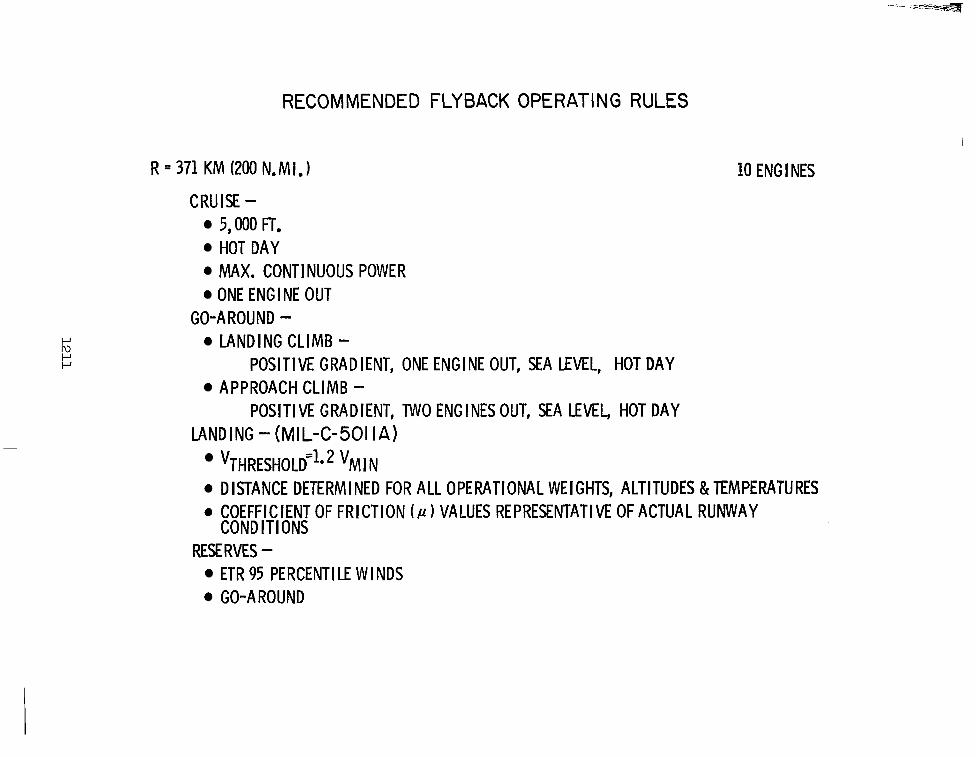
The recommended operating rules for flyback are summarized. On the basis of cruise and go-around thrust requirements, 10 engines are necessary to meet the proposed operating rules. From a landing performance consideration, the runway at Vandenberg Air Force Base must be increased to 3,050 meters (10,000 feet) to accommodate shuttle landings at heavy gross weights under wet-runway, hot-day conditions. Allowances for ETR 95 percentile headwinds and go-around provide an adequate reserve margin for flyback.
RECOMMENDED FLYBACK OPERATING RULES
R = 3 7 1 K M (200 N.MI.) 10 ENG I NES
CRUISE - 5,000 FT. HOT DAY MAX. CONTINUOUS POWER ONE ENGINE OUT
GO-AROUND - LANDING CLIMB -
POSITIVE GRADIENT, ONE ENGINE OUT, SEA LEVEL, HOT DAY
POSITIVE GRADIENT, TWO ENGINES OUT, SEA LEVEL, HOT DAY APPROACH CLIMB -
LANDING - (MIL-C-501 IA) VTHRESHOLD=~~ * VM I N DISTANCE DETERMINED FOR ALL OPERATIONAL WEIGHTS, ALTITUDES &TEMPERATURES
0 COEFFICIENT OF FRICTION ( P 1 VALUES REPRESENTATIVE OF ACTUAL RUNWAY CONDITIONS
RES€ RVES - ETR 95 PERCENT1 LE WINDS GO-AROUND
APPLICATION OF BASELINE VEHICLE TO FERRY OPERATIONS
The baseline Space Shuttle booster is designed for a flyback mission with limited range and altitude requirements. In adapting the vehicle to cross-country ferry operations, its capability must be improved to meet the range and altitude necessary for transcontinental flight. In addition, thrust improvements may be necessary to ensure adequate takeoff capability from candidate airfields. However, any improvements in aerodynamic efficiency and thrust capability needed for ferry flight must not compromise the design of the baseline vehicle.
APPLICATION OF BASELINE VEHICLE TO FERRY OPERATIONS
LIMITED RANGE
LIMITED ALTITUDE CAPABILITY
TRANSCONTINENTAL FERRY ROUTE
A representative ferry route across the continental United States from Vandenberg Air Force Base, California, to Kennedy Space Center, Florida, is presented. Because of the booster’s size and weight, only airfields capable of supporting B-52 aircraft operations are considered. The DOD Flight Information Publication IFR-Supplement United States was the principal source of information on candidate airfields. Distances between airfields were .obtained by scaling from standard USAF jet navigation charts. Existing runway lengths and field elevations are presented in meters, and the distances between airfields in kilometers, for the most conveniently spaced suitable airfields.

“.i. - -. .- T
FERRY ROUTE TERRAIN ELEVATIONS
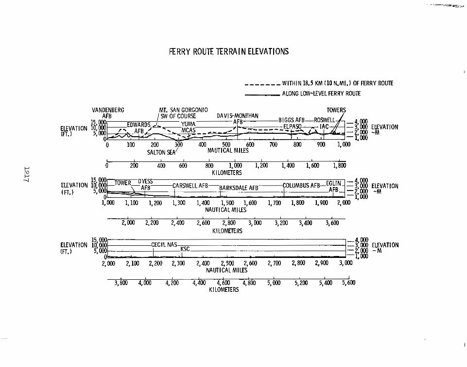
Terrain elevations along the proposed ferry route are shown. Because of the booster’s low cruise ceiling, consideration was given to terrain heights within 18.5 kilometers (10 nautical miles) of the direct course between airfields and along the lowest practical route between airfields. A flight altitude of at least 2,135 meters (7,000 feet) is required to clear terrain along the entire route. However, except for terrain elevations east of Davis-Monthan Air Force Base and west of Roswell Industrial Air Center, a flight altitude of 1,525 meters (5,000 feet) is sufficient to meet terrain requirements along low-level routes between points.
FERRY ROUTE TERRAIN ELEVATIONS
U
_ _ _ _ _ _ _ W I T H I N 18.5 K M (10 N.MI.1 OF FERRY ROUTE
ALONG LOW-LEVEL FERRY ROUTE
VANDENBERG MT. SAN GORGON10 TOWERS AFB SW OF COURSE DAVIS"oNTl-!AN
AFB B I
(FT. I I
0 100 200 300 400 500 600 700 800 900 1,000 SA LTO N SEA' NAUTICAL MILES
L I I I I I I I I I
0 200 400 600 800 1,000 1,200 1,400 1,600 1,800 K I LOMETE RS
ELEVATION 10, OOo - 15, Oo0 TOWER D E S S $ARSWELLAFB-BARKSDALE AFB COLUMBUS AFB-EGLIN- - 3: 000 ELEVATION
-4 000
AFB--2 ay~ -M (FT.1 5, 000c -1 AFB-
0 1,OOO 1,100 1,200 1,300 1,400 1,500 1,600 1,700 1,800 1,900 2,000
NAUTlCAt MILES
I d I 1 ~ - - 1 : 0 0 0
I I I 6 I 1
2,000 2,200 2,400 2,600 2,800 3,000 3,200 3,400 3,600 K 1 LOMETE RS
ELEVATION 10 000 15, 000
(FT. I CECIL NAS Ksc -4 000
5: ooo I -2'000 - M - -3,000 ELEVATION
0-8 ' -1:000 2,000 2,100 2,200 2,300 2,400 2,500 2,600 2,700 2,800 2,900 3,000
NAUTICAL MILES I t 0 I I I I I
3,800 4,000 4,200 4,400 4,600 4,800 5,000 5,200 5,400 5,600 K I LOMETE RS
I
THRUST REQUIRED
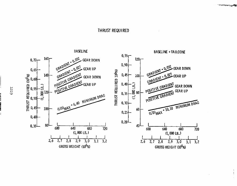
The thrust required to meet the FAR Part 25 climb gradients for the baseline ferry configuration is presented together with that needed to maintain a positive gradient for the landing and approach configuration. The thrust necessary to maintain minimum drag levels is also presented for the clean configuration (L/Dmax = 6.40) as a function of gross weight.
The thrust levels for the same requirements are also presented for the baseline vehicle, with the addition of a tailcone fairing over the base. Since almost 50% of the booster subsonic drag is base drag, the addition of a tailcone aft of the vehicle base which produces a faired fuselage results in a considerable decrease in vehicle drag levels and improved aerodynamic efficiency (L/Dmax = 10.10).
THRUST REQU I RED
0.70- 160
0.65
3 0.60-
- A z 140
cr
n 5 0.55-2 W
h
s 5i
Q 120 W
0.50-6 3
0.45-
- 0.40
100
BASELl NE
0.35 L 8 0 L 1 600 640 680 720 (1, OOO LB. 1
GROSS WE I GHT (106N)
0.50 0*55r 120
BASELI NE + TA I LCONE -
-9 600 640 .680 720
(1, OOO LB. 1
2.6 2.7 2.8 2.9 3.0 3.1 3.2 GROSS WE I GHT (106N)
REQUIRED NUMBER OF ENGINES
Iv 0
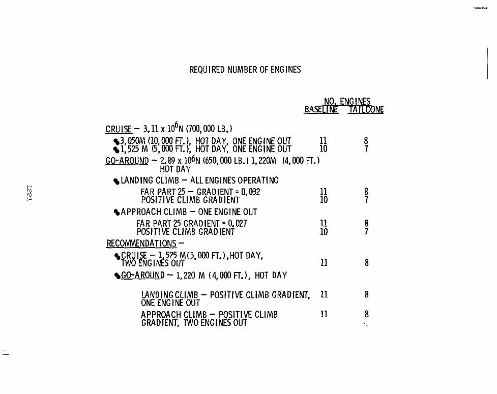
The effect of the decreased vehicle drag levels resulting from the addition of a tailcone fairing is shown by the reduced number of cruise engines required to maintain adequate cruise and go-around performance. The baseline configuration with tailcone reduces by three the number of engines necessary to maintain hot-day cruise performance at 1,525 meters (5,000 feet) and 3,050 meters (10,000 feet) and hot-day go-around performance at 1,220 meters (4,000 feet). This is a distinct advantage of the tailcone modification under ferry flight operating conditions that necessitate increased thrust capability to the baseline vehicle and hence additional engines.
Recommended operating conditions and engine requirements for cruise and go-around are also presented. Because of the low minimum cruise altitude (1,525 meters or 5,000 feet) along the ferry route, the high temperatures expected to be encountered in the southern United States, and the large number of required engines, an absolute ceiling capability of 1,525 meters (5,000 feet) on a hot day with two engines inoperative at maximum continuous power is recommended for cruise. Under these emergency conditions, when additional altitude capability is required to clear terrain east of Davis-Monthan and west of Roswell, intermediate power may be used. As for flyback, recommended go-around operating rules increase the number of inoperative engines specified by FAR Part 25 from none to one for the landing configuration, and from one to two for the approach configuration because of the large number of engines. Performance must be calculated at 1,220 meters (4,000 feet) elevation on a hot day to cover the range of airfield elevations and expected temperatures. A positive climb gradient capability is considered sufficient under these emergency conditions.
Eleven engines are required for the baseline vehicle to meet these recommended operating rules; this is one more than the baseline requirement for flyback. The addition of the tailcone reduces this number to eight engines, well within the flyback limit of 10.
REQU I RED NUMBER OF ENG I NES
NO. ENGINES BASE1 I Nt TA I LCONE
3,050M (10,000 FT. 1, HOT DAY, ONE ENGINE OUT 11 1,525 M (5,000 FT. 1, HOT DAY, ONE ENGINE OUT 10
8 7
GO-AROUND - 2.89 X 10⁶N (650, OOO LB. 1 1,220M (4, OOO FT. 1 HOT DAY
LANDING CLIMB - ALL ENGINES OPERATING FAR PART 25 - GRADIENT = 0.032 11 8 POSITIVE CLIMB GRADIENT 10 7
FAR PART 25 GRADIENT = 0.027 11 8 POSITIVE CLIMB GRADIENT 10 7
APPROACH CLIMB - ONE ENGINE OUT
RECONMENDATIONS - fW - 1 525 M(5,000 FT.),HOT DAY,
W NG I N t S OUT GO-A ROUND - 1,220 M ( 4,000 FT. 1, HOT DAY
11 8
LANDINGCLIMB - POSITIVE CLIMB GRADIENT, 11 8 ONE ENGINE OUT APPROACH CLIMB - POSITIVE CLIMB 11 8 GRADIENT, TWO ENGINES OUT
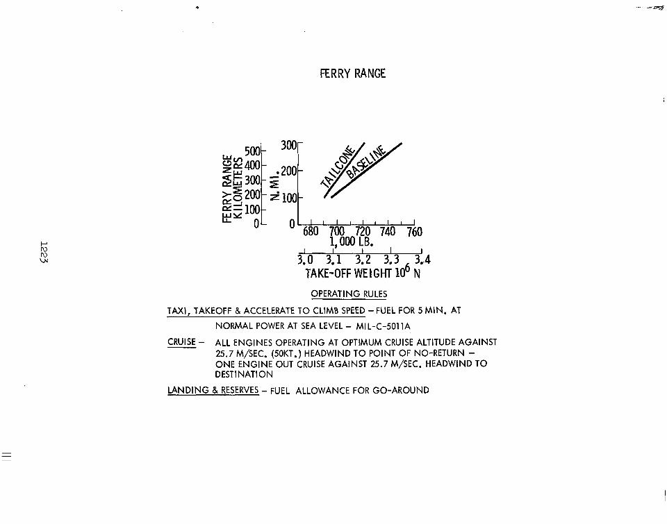
FERRY RANGE
Vehicle ferry range is presented as a function of takeoff gross weight for the baseline vehicle and the baseline with a tailcone. The improved aerodynamic efficiency of the tailcone configuration not only results in reduced engine requirements because of lower drag levels, but also increased cruise range for a given takeoff gross weight.
Recommended operating rules for flight planning are presented. Fuel for taxi, takeoff, and acceleration to climb speed is five minutes at normal rated power (maximum continuous) at sea level. Taken from MIL-C-5011A requirements for transport aircraft, this is adequate for shuttle ferry operations. Recommended cruise operation consists of flight against a 25.7 meters-per-second (50-knot) headwind with all engines operating at the optimum cruise altitude to the point of no return on a standard day, loss of one engine, and one-engine-out cruise from the point of no return to the destination. A 25.7 meters-per-second (50-knot) headwind is commonly used by airline operators for transcontinental flight planning purposes and is considered satisfactory for shuttle ferry flight planning. The point of no return is defined as that point on the flight trajectory from which the vehicle can return to the takeoff site or continue to the destination using all of the remaining cruise fuel on board. A fuel allowance for one aborted landing attempt and go-around in the landing configuration is recommended for flight reserves.
FERRY RANGE
P Iu
w Iu 310 3; 1 312 313 31.4 TAKE-OFF WE 1 GHT 10 N
OPERATING RULES
TAXI, TAKEOFF & ACCELERATE TO CLIMB SPEED -FUEL FOR 5 MIN. AT
NORMAL POWER AT SEA LEVEL - MI L-C-5011A
CRUISE - ALL ENGINES OPERATING AT OPTIMUM CRUISE ALTITUDE AGAINST 25.7 M/SEC. (50KT.) HEADWIND TO POINT OF NO-RETURN - ONE ENGINE OUT CRUISE AGAINST 25.7 M/SEC. HEADWIND TO DESTINATION
LANDING & RESERVES - FUEL ALLOWANCE FOR GO-AROUND
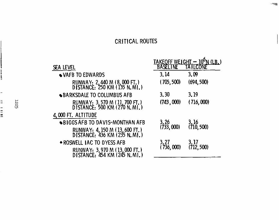
CRITICAL ROUTES
The critical routes for the transcontinental ferry operation are presented. These flight segments are considered critical because of their limited field length capability for the takeoff gross weights required to meet the specified ranges.
C R I T I C A L ROUTES
SEA LEVEL VAFB TO EDWARDS
RUNWAY: 2 440M ( 8 OOO FT,) DISTANCE: 250 K M ( f35 N. MI.
BARKSDALE TO COLUMBUS AFB RUNWAY: 3 570 M (11 700 FT. DISTANCE: $00 K M (270 N. MI.
4, OOO FT. ALTITUDE BIGGSAWTO DAVIS-MONTHAN AFB
RUNWAY: 4,150 M ( 13 600 FT. 1 DISTANCE: 436 KM (23’5 N . M I . 1
OROWELL IAC TO DYESS AFB RUNWAY: 3,970 M ( 13 OOO FT. DISTANCE: 454 KM (245 N.MI.)
TAKEOFF WE1 GHT - 106N a) BASELl NE TA I LCONE
3.14 3.09 ( 705,500) (694,500)
3.30 3.19 (743, OOO) ( 716, OOO)
TAKEOFF RULES
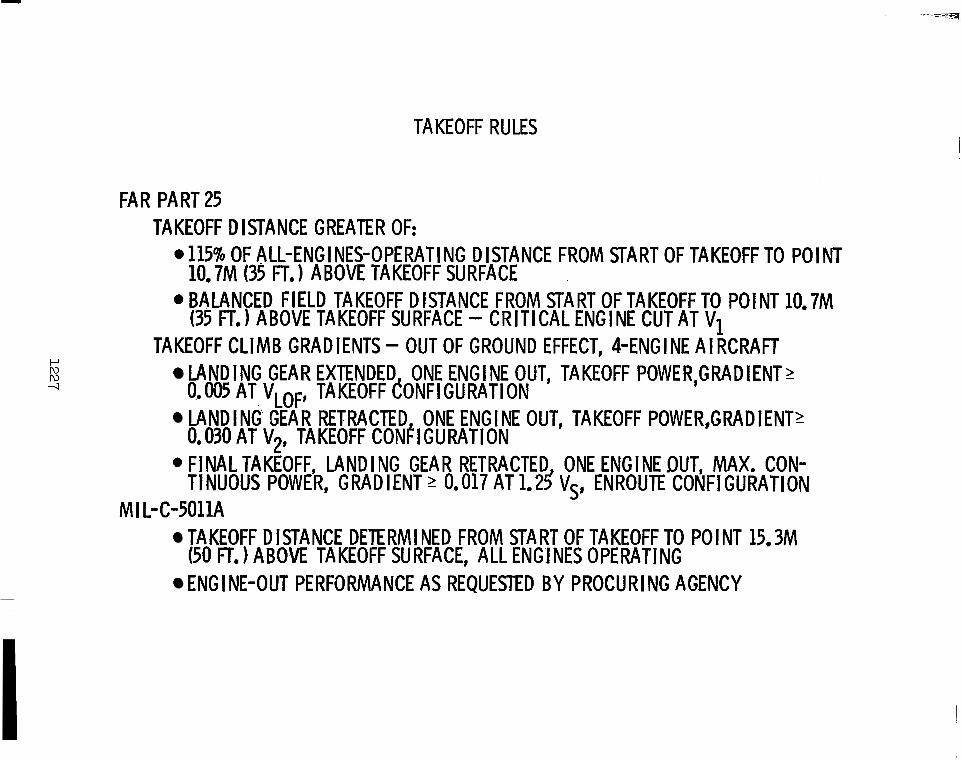
The takeoff operating rules required by FAR Part 25 and MIL-C-5011A are presented. Because of the large number of cruise engines on the booster vehicle, 115% of the all-engines operating distance is greater than the FAR balanced field takeoff distance, with the critical engine made inoperative during the ground roll. According to FAR Part 25, the greater of the two distances is the required takeoff distance.
The critical FAR takeoff condition resulting in the greatest thrust requirement is the takeoff segment with landing gear retracted with a required climb gradient of 0.030. However, the number of engines necessary to meet this gradient is less than the number required to meet the final takeoff gradient of 0.017 with landing gear retracted, since the throttle setting for the latter is maximum continuous power.
The takeoff distance as defined by MIL-C-5011A is determined from start of ground roll to a point 15.25 meters (50 feet) above the takeoff surface with all engines operating. Engine-out takeoff performance is required if requested by the procuring agency. No climb gradient after liftoff is specified. However, the takeoff gross weight is limited by a 0.508 meters-per-second (100 feet-per-minute) rate-of-climb capability at sea level on a hot day with one engine inoperative.
TAKEOFF RULES
FA R PART 25 TAKEOFF DISTANCE GREATER OF:
0115% OF ALL-ENGINES-OPERATING DISTANCE FROM START OF TAKEOFF TO POINT 10.7M (35 FT.) ABOVE TAKEOFF SURFACE
.BALANCED FIELD TAKEOFF DISTANCE FROM START OFTAKEOFFTO POINT 10.7M (35 FT.) ABOVE TAKEOFF SURFACE CRITICAL ENGINE CUT AT V1
TAKEOFF CLIMB GRADIENTS - OUT OF GROUND EFFECT, 4-ENGINE AIRCRAFT M N D I N G GEAR EXTENDED ONE ENGINE OUT, TAKEOFF POWER,GRADIENT? 0.005 AT VLoF, TAKEOFF CONFIGURATION LANDING GEAR RETRACTED ONE ENGINE OUT, TAKEOFF POWER,GRADIENTZ 0.030 AT v,, TAKEOFF CON~IGURATION
9 FINAL TAKFOFF, LANDING GEAR RETRACTED ONE ENGINE DUT, MAX. CON- TINUOUS POWER, GRADIENT 2 0.017 AT 1.25 Vs, ENROUTE CONFIGURATION
MI L-C-5011A TAKEOFF D I STANCE DETE RM I NED FROM STA RT OF TAKEOFF TO PO I NT 15.3M (50 F L ) ABOVE TAKEOFF SURFACE, ALL ENGINES OPERATING ENGl NE-OUT PERFORMANCE AS REQUESTED BY PROCURING AGENCY
U
Iu Iu co
TAKEOFF PERFORMANCE Baseline
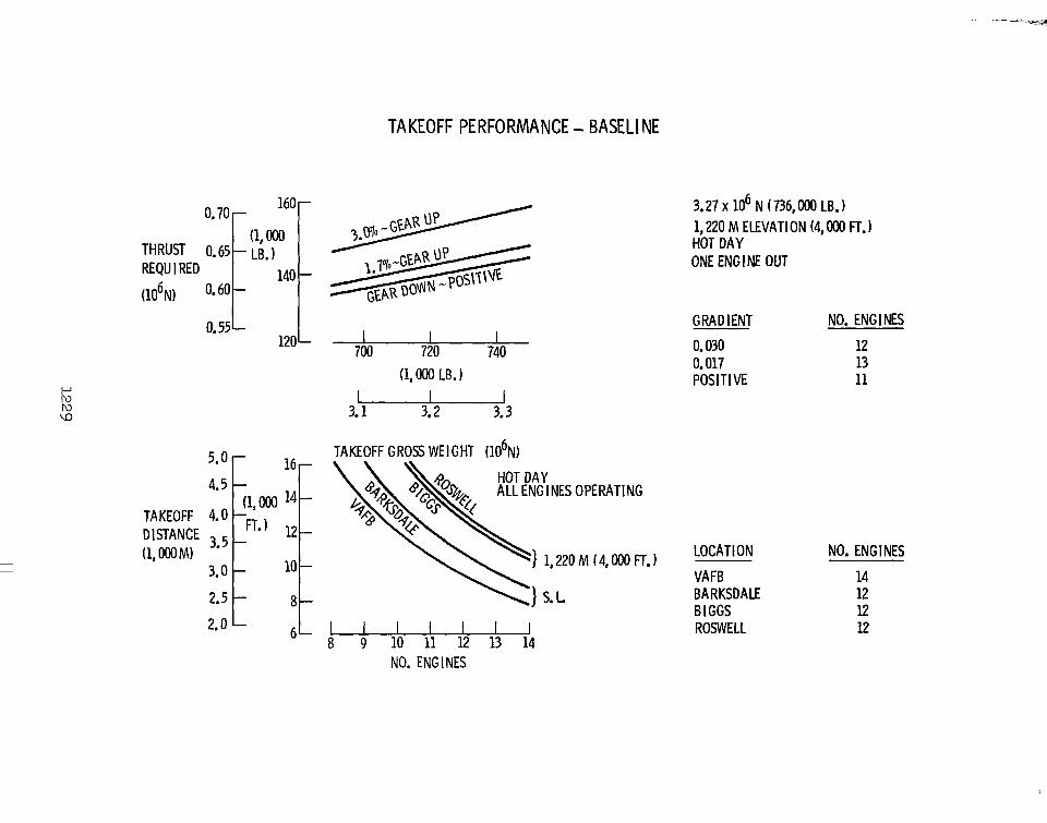
The thrust required to meet the FAR Part 25 critical takeoff climb gradients is presented as a function of vehicle takeoff gross weight for the baseline configuration, together with the thrust necessary to meet a positive gradient. For the critical 1,200-meter (4,000-foot) elevation, hot-day condit.ion, 13 engines are needed to meet the FAR final takeoff gradient of 0.017 with one engine inoperative; whereas only 11 engines are needed to maintain a positive gradient with gear down. This is still one more engine than is required for baseline flyback operations.
The baseline vehicle takeoff performance along the critical ferry routes further reveals the inadequate thrust capability of the baseline booster for ferry operations. Under hot-day conditions, with all engines operating, 14 engines are needed to meet takeoff requirements from Vandenberg Air Force Base, California; 12 engines are needed to meet requirements from the remaining three airfields.
TAKEOFF PERFORMANCE - BASELl NE
U
- 700 720 740 (1, OOO LB. 1 -
3.1 3.2 3.3
5.0
4.5
TAKEOFF 4.0 DISTANCE 3.5 (1,000M)
3.0
2.5
2.0
3 . 2 7 ~ lo6 N (736,ooO LB.) 1,220 M ELEVATION (4, OOO Fr. 1 HOT DAY ONE ENGINE OUT
GRADIENT NO. ENG I NES
0.030 12 0.017 13 POSITIVE 11
- TAKEOFF GROSS WEIGHT (106N)
LOCATION NO. ENG 1 NES
VAFB 14 BARKSDALE 12 B I GGS 12
- 6L 8 9 10 11 12 13 14
NO. ENGINES
ROSWELL 12
P Iu w 0
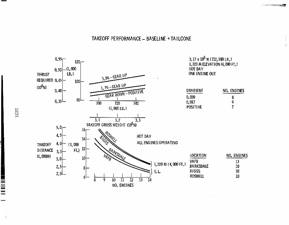
TAKEOFF PERFORMANCE Baseline with Tailcone
The tailcone configuration thrust requirements to meet the FAR Part 25 critical takeoff climb gradients and a positive climb gradient are presented as a function of takeoff gross weight. The addition of the tailcone fairing reduces the number of required engines to meet the FAR final takeoff climb gradient of 0.017 from 13 for the baseline vehicle to nine, with one engine inoperative. Only seven engines are needed to maintain a positive climb gradient with gear down.
Tailcone configuration takeoff performance is presented for the critical ferry routes as a function of number of operating engines for hot-day conditions with all engines operating. Thirteen engines are needed to meet takeoff requirements from Vandenberg Air Force Base, California, whereas 10 are required for the remaining critical routes.
TAKEOFF PERFORMANCE - BASELINE +TAILCONE
0.50 0*551 (l,OoO 1 2 0 r THRUST REQU I RED 0: 45 1 LB*
(106N) 0.40
0.35 700 720 740 (1,000 LB. 1
3.1 3.2 3.3 " TAKEOFF GROSS WEIGHT (106N)
3.17 x lo6 N ( 712,500 LB. 1 1,220 M ELEVATION (4, OOO FT. 1 HOT DAY ONE ENGINE OUT
GRADIENT NO. ENG I NES 0.030 8 0.017 9 POSIT1 VE 7
3. U
TAKEOFF 4 - i (1, r, 4.5
DISTANCE 3 5
2.5 2.0
16
(1,WM) 3.0
ALL ENGINES OPERATING
LOCATION VAFB ) 1,220M (4,0°0 m*) BARKSDAE
u 1 S.L B IGGS ROSWELL
8 9 10 11 12 13 14 NO. ENG I NES
NO. ENG I NES 13 10 10 10
FERRY PERFORMANCE Baseline with Tailcone
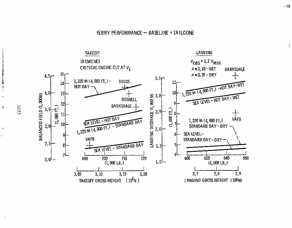
Takeoff and landing performance for the baseline vehicle with a tailcone is presented. Balanced field takeoff performance according to FAR Part 25 is recommended for shuttle operations to maintain satisfactory safety margins without unnecessarily penalizing vehicle performance. A balanced field takeoff is one in which the distance required to complete the takeoff equals the distance necessary to decelerate and stop the vehicle when the critical engine is suddenly made inoperative. The speed at which this occurs is defined as the critical engine failure speed, VI.
Balanced field length is presented for a 10-engine vehicle as a function of takeoff gross weight for standard and hot-day conditions at sea level and at 1,220 meters (4,000 feet). All runway lengths are adequate for standard-day operation from the critical locations along the transcontinental ferry route. However, Vandenberg Air Force Base is approximately 747 meters (2,450 feet) short of the required field length for hot-day operation at sea level, and Roswell Industrial Air Center is 183 meters (600 feet) short of its required field length for hot-day operations at 1,220 meters (4,000 feet). Runway extensions at both these fields must be considered if balanced field takeoff requirements are to be met without the addition of engines to the baseline vehicle.
Recommended landing performance is calculated for an obstacle speed of 1.2 Vmh. Landing distance is presented as a function of landing gross weight for standard-day, dry, and hot-day, wet conditions at sea level and 1,220 meters (4,000 feet). Only Vandenberg Air Force Base falls short of the hot-day, wet landing distance requirements; all other locations have adequate field lengths to meet these requirements.
FERRY PERFORMANCE - BASELl NE + TA I LCONE
TAKEOFF LAND I NG
4.5- - l5
14 -
- 4.0- 13
6
-
3 - 5 4 0
12- 8
g 3 . 0 3 - 10-
Q
9- S
11- L L n
2 2.5 - 8 -
7- 2. O L
10 ENG I NES CRITICAL ENGINE CUT AT V1
1,220 M (4,000 FT.1- BIGGS HOT D Y -.-
ROSWELL BARKSDALE -!-
690 700 710 720 L (1, OOO LB. 1 1.0
VOSS‘ l a 2 V~~~ P 0.10 -WET BARKSDALE P 0.35-DRY I
7-
I I
1,220 M (4,000 FT.1 VAFB STANDARD DAY - DRY -\
-.-
SEA LEVEL- \ STANDARD DAY -DRY-
600 620 640 660 (1, OOO LB. 1
3.05 3.10 3.15 3.20 TAKEOFF GROSS WEIGHT ( 106N )
2.7 2.8 2.9 LANDING GROSS WEIGHT (106N3
FERRY PERFORMANCE Operating Rules
The recommended operating rules for ferry performance are summarized. These rules are compatible with those for the baseline flyback mission, insofar as they do not necessitate major design changes to the vehicle, yet ensure adequate safety margins. The addition of the tailcone fairing provides performance capability for ferry with the same number of engines required by flyback operating rules, with modifications required to only two candidate airfields along the proposed ferry route under hot-day conditions.
Means other than a tailcone fairing for improving ferry performance were considered,, i.e., additional engines and engines with afterburners. However, the additional expense and maintenance time required for these modifications do not warrant their consideration for ferry operations, when compared to the procedure of adding a tailcone fairing.
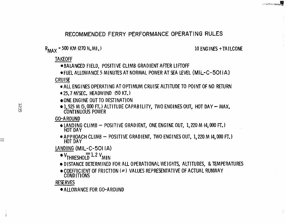
RECOMMENDED FERRY PERFORMANCE OPERATING RULES
RMAx = 500 K M (270 N.MI.1 10 ENG I NES + TA I LCONE
TAKEOFF @BALANCED FIELD, POSITIVE CLIMB GRADIENT AFTER LIFTOFF @FUEL ALLOWANCE 5 MINUTES AT NORMAL POWER AT SEA LEVEL (MIL-C-501 IA)
@ A L L ENGINES OPERATING AT OPTIMUM CRUISE ALTITUDE TO POINT OF NO RETURN a 25.7 MISEC. HEADW I ND (50 KT. )
ONE ENGINE OUT TO DESTl NATION 1,525 M (5,000 FT.) ALTITUDE CAPABILITY, TWO ENGINES OUT, HOT DAY - MAX.
CRUISE
CONTl NUOUS POWER GO-AROUND
LANDING CLIMB - POSITIVE GRADIENT, ONE ENGINE OUT, 1,220 M (4,000 FT.) HOT DAY
.APPROACH CLIMB - POSITIVE GRADIENT, TWO ENGINESOUT, 1,220 M (4,000 FT.1 HOT DAY
LANDING (MIL-C-501 IA) - v~~~~~~~~~ -11.2 V M I N DISTANCE DETERMINED FOR ALL OPERATIONAL WEIGHTS, ALTITUDES, &TEMPERATURES COEFFICIENT OF FRICTION ( N VALUES REPRESENTATIVE OF ACTUAL RUNWAY COND IT1 ONS
RESE RVES ALLOWANCE FOR GO-AROUND
SUMMARY
A set of flyback and ferry operating rules have been recommended that provide safe flight operations and adequate reserves. Of prime importance, the recommended ferry rules do not compromise design of the baseline vehicle. For the configuration investigated herein, 10 engines are required to meet the flyback operating rules. Addition of a tailcone fairing and extension of two of the runways along the transcontinental ferry route are the only modifications necessary to meet the recommended ferry operating rules. No additional engines are required.
SUMMARY
FLYBACK OPERATING RULES SAFE OPERATIONS ADEQUATE RESERVES
FERRY OPERATING RULES SAFE OPERATIONS ADEQUATE RESERVES NO COMPROMISE TO BASELINE DESIGN