Embed Size (px)
Citation preview
EFFECT OF CORROSION ON ALUMINIUM TAILOR WELDED BLANKS
(SIMILAR MATERIAL WELDING)
MUHAMMAD FIRDAUS BIN AB MOIN
Thesis submitted in fulfillment of the requirements
for the award of the degree of
Bachelor of Mechanical Engineering
Faculty of Mechanical Engineering
UNIVERSITI MALAYSIA PAHANG
JUNE 2013
vii
ABSTRACT
In this study, the effect of corrosion on aluminium tailor welded blank with similar
metal of aluminium type AA 1100 with different thickness joint by using filler ER 4043
and filler ER 4047 was investigated. Tungsten Inert gas (TIG) was used for butt welding
of the process. Corrosion test was tested in 3.5 % Sodium Chloride (NaCl) solution by
immersed the specimen for 30 days. Microstructure of base metal (BM), fusion zone
(FZ), and heat affected zone (HAZ) was study with image analyzer. Tensile properties
of welded joint were investigated by tensile test and hardness of the FZ, HAZ and BM
was obtained by Vickers hardness test. From the corrosion test result, it shows that
specimen weld by filler ER 4047 has good corrosion resistance than specimen weld by
filler ER 4043. The data observed also show that the hardness and tensile properties of
welded joint did decrease after the corrosion test. Microstructure at the FZ, HAZ and
BM also change with the existence of pitting corrosion.
viii
ABSTRAK
Kesan kakisan pada aluminium plat yang di sambung melalui teknik penyambungan
kekal iaitu kimpalan di kaji di dalam tesis ini. Kaedah kimpalan pada plat aluminium
yang berlainan tebal atau dipangil Tailor Welded Blanks diaplikasikan untuk kajian ini.
Dua jenis pengisi digunakan untuk proses kimpalan iaitu ER 4043 dan ER 4047 dalam
kajian ini. Proses kakisan di jalankan untuk komponen yang di sambung di uji melalui
rendaman dalam larutan 3.5 % Sodium Chloride (NaCl). Tungsten Inner Gas (TIG)
adalah teknik kimpalan yang di gunakan. Mikrostruktur sambungan pada zon Fusion
(FZ), zon Heat Affected (HAZ) dan zon asas aluminium (BM) di kaji pada sebelum dan
selepas proses kakisan. Sifat tegangan pada sambungan juga di kaji melalui ujian
tegangan. Tahap kekerasan pada tiga zon iaitu FZ, HAZ dan BM juga di kaji. Hasil dari
keputusan ujian kakisan menunjukan sambungan yang mengunakan pengisi ER 4047
mempunyai keputusan yang lebih baik dari sambungan yang mengunakan pengisi ER
4043 dari segi kadar pengaratan. Keputusan kajian juga menunjukan sifat tegangan dan
kekerasan sambungan berkurangan selepas proses kakisan. Mikrostruktur pada FZ,
HAZ, dan BM juga berubah dengan kehadiran bopeng.

ix
TABLE OF CONTENTS
Page
SUPERVISOR’S DECLARATION
EXAMINER’S APPROVAL DOCUMENT
ii
iii
STUDENT’S DECLARATION
DEDICATION
iv
v
ACKNOWLEDGEMENTS vi
ABSTRACT vii
ABSTRAK viii
TABLE OF CONTENTS ix
LIST OF TABLES xi
LIST OF FIGURES xii
LIST OF SYMBOLS xiii
LIST OF ABBREVIATIONS xiv
CHAPTER 1 INTRODUCTION
1.1 Background 1
1.3 Problem Statement 2
1.3 Objectives of the Project 2
1.4 Scope of Study 3
CHAPTER 2 LITERATURE REVIEW
2.1 Introduction Of Tailor Welded Blank (TWB)
2.1.1 Similar Material Of TWB
4
6
2.2 Welding Process
2.2.1 Tungsten Inert Gas Welding (TIG)
2.2.2 Metal Inert Gas Welding (MIG)
2.2.3 Filler Types
2.2.4 Joining Design
6
7
7
8
9
2.3 Materials 10
1 × ENTER (1.5 line spacing)

x
2.3.1 Aluminium 10
2.3.2 Aluminium Alloy AA1100 11
2.4 Corrosion 13
2.4.1 Types of Corrosion
2.4.1.1 Uniform Attack Corrosion
2.4.1.2 Pitting Corrosion
2.4.1.3 Intergranular Corrosion
2.4.1.4 Stress Corrosion Cracking (SCC)
2.4.1.5 Galvanic Corrosion
15
15
16
17
17
18
2.4.2 Effect of Corrosion Weldments 19
CHAPTER 3 METHODOLOGY
3.1 Introduction 21
3.2 Experiment Setup
3.2.1 Substrate Material
3.2.2 Joining Process
3.2.3 Specimen Cut-Off
3.2.4 Mounting
3.2.5 Polishing
23
23
24
25
26
26
3.3 Analysis Testing
3.3.1 Optical Observation
3.3.2 Hardness Test
3.3.3 Tensile Test
27
27
28
29
3.4 Corrosion Test 30
CHAPTER 4 RESULTS AND DISCUSSION
4.1 Introduction 31
4.2 Microstructure Analysis 31
4.3
4.4
Corrosion On The Weldment
4.3.1 Corrosion Rate
4.3.2 Microstructure Analysis After Corrosion
Hardness Test
38
38
39
44

xi
4.5
4.6
Tensile Test
Discussion
51
58
CHAPTER 5 CONCLUSION AND RECOMMENDATIONS
5.1 Introduction 60
5.2 Conclusions 60
5.3 Recommendations for the Future Research 61
REFERENCES 62
xii
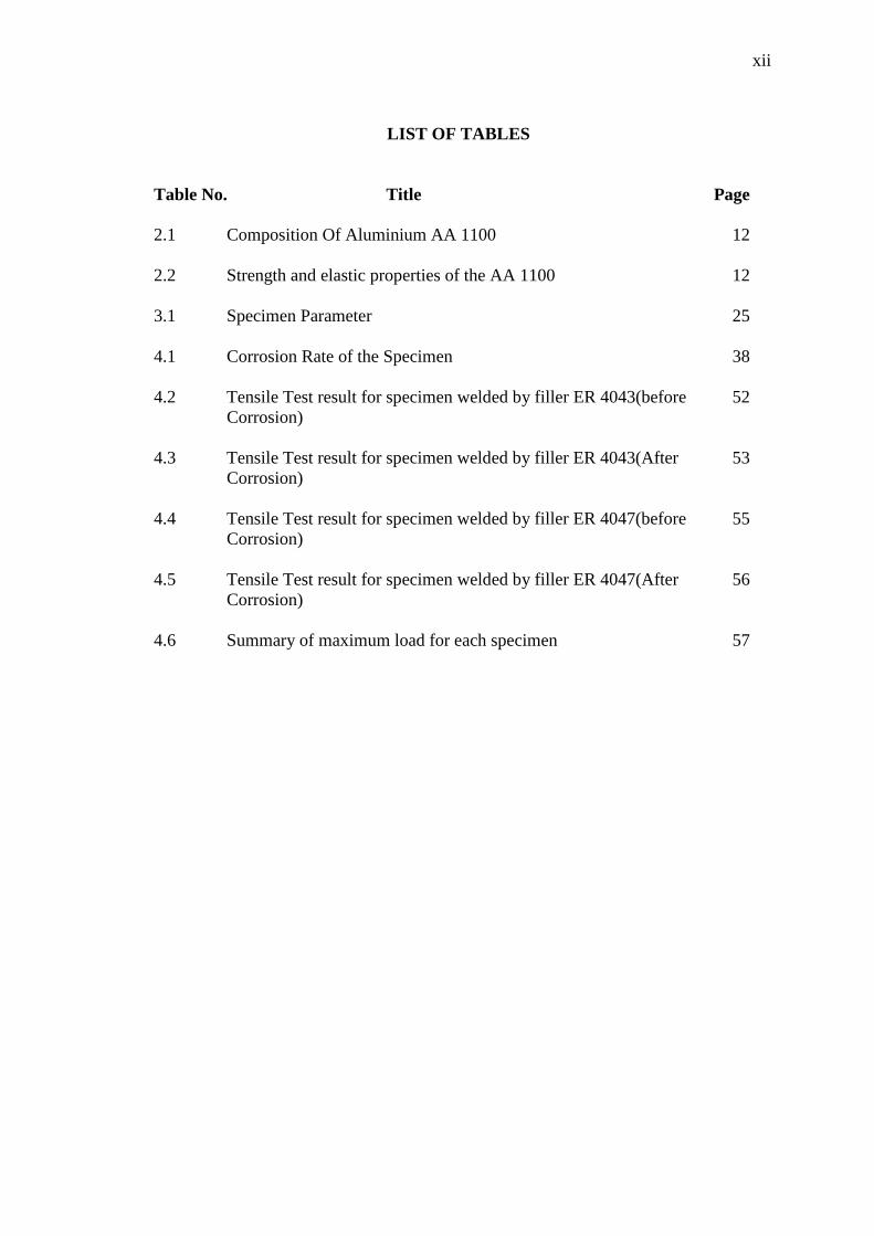
LIST OF TABLES
Table No. Title Page
2.1 Composition Of Aluminium AA 1100
12
2.2 Strength and elastic properties of the AA 1100
12
3.1 Specimen Parameter
25
4.1 Corrosion Rate of the Specimen 38
4.2 Tensile Test result for specimen welded by filler ER 4043(before
Corrosion)
52
4.3 Tensile Test result for specimen welded by filler ER 4043(After
Corrosion)
53
4.4 Tensile Test result for specimen welded by filler ER 4047(before
Corrosion)
55
4.5 Tensile Test result for specimen welded by filler ER 4047(After
Corrosion)
56
4.6 Summary of maximum load for each specimen 57

xiii
LIST OF FIGURES
Figure No. Title Page
2.1 View of current and potential automotive tailor welded blank
applications
5
2.2 Butt Joint 9
2.3 Lap Joint 9
2.4 Comparison of Al 5083 and mild steel 11
2.5 Aluminium alloy strength according to different grades 11
2.6 Uniform attack corrosion 15
2.7
2.8
Pitting Corrosion
Intergranular Corrosion
16
17
2.9
2.10
Stress Corrosion Cracking
Galvanic Corrosion
18
19
3.1 Flow Chart 22
3.2 Work Piece 23
3.3 Shearing machine 23
3.4
3.5
3.6
3.7
3.8
3.9
3.10
3.11
3.12
Lap Joint
TIG welding machine
Sectioning Cut-Off Machine
Cold Mounting Machine
Roll Grinder Machine
Forcipol 2V Grinder-Polisher
Optical Microscopes
Vickers Hardness process
Tensile Test Machine
24
24
25
26
27
27
28
28
30
xiv
4.1
4.2
4.3
4.4
4.5
4.6
4.7
4.8
4.9
4.10
4.11
4.12
4.13
4.14
4.15
4.16
Microstructure of specimen with thickness ratio 1.5 and welded by
using filler ER 4043
Microstructure of specimen with thickness ratio 2 and welded by
using filler ER 4043
Microstructure of specimen with thickness ratio 3 and welded by
using filler ER 4043
Microstructure of specimen with thickness ratio 1.5 and welded by
using filler ER 4047
Microstructure of specimen with thickness ratio 2 and welded by
using filler ER 4047
Microstructure of specimen with thickness ratio 3 and welded by
using filler ER 4047
Microstructure of specimen with thickness ratio 1.5 and welded by
using filler ER 4043 (after corrosion).
Microstructure of specimen with thickness ratio 2 and welded by
using filler ER 4043 (after corrosion).
Microstructure of specimen with thickness ratio 3 and welded by
using filler ER 4043
Microstructure of specimen with thickness ratio 1.5 and welded by
using filler ER 4047
Microstructure of specimen with thickness ratio 2 and welded by
using filler ER 4047
Microstructure of specimen with thickness ratio 3 and welded by
using filler ER 4047
Hardness Profile across welded area of specimen weld by using
filler ER 4043 (Before and after corrosion)
Hardness Profile across welded area of specimen weld by using
filler ER 4043 (Before and after corrosion)
Hardness Profile across welded area of specimen weld by using
filler ER 4043 (Before and after corrosion)
Hardness Profile across welded area of specimen weld by using
filler ER 4047 (Before and after corrosion)
32
33
34
35
36
37
39
40
41
42
43
43
45
46
47
48
xv
4.17
4.18
4.19
4.20
4.21
4.22
Hardness Profile across welded area of specimen weld by using
filler ER 4047 (Before and after corrosion)
Hardness Profile across welded area of specimen weld by using
filler ER 4047 (Before and after corrosion)
Tensile Stress (Mpa) vs % Strain curve for specimen with
different thickness ratio by using filler ER 4043(Before corrosion)
Tensile Stress (Mpa) vs % Strain curve for specimen with
different thickness ratio by using filler ER 4043(after corrosion)
Tensile Stress (Mpa) vs % Strain curve for specimen with
different thickness ratio by using filler ER 4047(Before corrosion)
Tensile Stress (Mpa) vs % Strain curve for specimen with
different thickness ratio by using filler ER 4047(After corrosion)
49
50
52
53
55
56

xvi
LIST OF SYMBOLS
HV Hardness
P Load
d
the average length of the diagonals
Ɵ angle between opposite faces of the diamond (usually measured as
136o)
σ Stress
Ao Initial cross-sectional area
lo Initial gage length
e
W
A
D
K
T
Strain
Mass loss
Area
Density
Constant
time of exposure in hours

xvii
LIST OF ABBREVIATIONS
ASTM
BM
FZ
HAZ
MIG
SCC
American Society for Testing and Materials
Base Metal
Fusion Zone
Heat Affected Zone
Metal Inert Gas
Stress Corrosion Cracking
TIG Tungsten Inert Gas
TWB Tailor Welded Blank
1
CHAPTER 1
INTRODUCTION
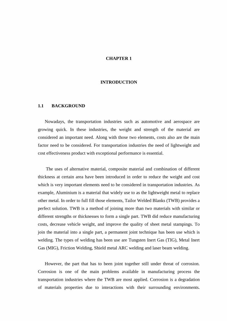
1.1 BACKGROUND
Nowadays, the transportation industries such as automotive and aerospace are
growing quick. In these industries, the weight and strength of the material are
considered an important need. Along with those two elements, costs also are the main
factor need to be considered. For transportation industries the need of lightweight and
cost effectiveness product with exceptional performance is essential.
The uses of alternative material, composite material and combination of different
thickness at certain area have been introduced in order to reduce the weight and cost
which is very important elements need to be considered in transportation industries. As
example, Aluminium is a material that widely use to as the lightweight metal to replace
other metal. In order to full fill those elements, Tailor Welded Blanks (TWB) provides a
perfect solution. TWB is a method of joining more than two materials with similar or
different strengths or thicknesses to form a single part. TWB did reduce manufacturing
costs, decrease vehicle weight, and improve the quality of sheet metal stampings. To
join the material into a single part, a permanent joint technique has been use which is
welding. The types of welding has been use are Tungsten Inert Gas (TIG), Metal Inert
Gas (MIG), Friction Welding, Shield metal ARC welding and laser beam welding.
However, the part that has to been joint together still under threat of corrosion.
Corrosion is one of the main problems available in manufacturing process the
transportation industries where the TWB are most applied. Corrosion is a degradation
of materials properties due to interactions with their surrounding environments.

2
Corrosion makes the strength of the joint decrease gradually and affects the strength of
part. Microstructure features of welded joint need to recognize in order to predict and
understand the acceptable corrosion for the welded joint. There are several welding
techniques can be applied to minimize the effect of corrosion. One of the methods
utilized to minimize the corrosion on welded joint is surface preparation. The proper
cleaning process before the welding process is important in reducing defects that are
often offered a site for corrosive attack in aggressive environments. The other method
are joining design, welding practice and surface finish.
1.2 PROBLEM STATEMENT
To join a material with a different thickness is not a simple task. In purpose to
joint that kind of joining, TWB method is applied for joining two different thicknesses
quite challenging when the thinner part will melting first than the thicker part. That will
affect the welded joint. Corrosion did affect the microstructure and strength of the weld
joint. The hardness of the joint is decreasing since the corrosion occurs. The different
types of filer used while joining the part give the different result of corrosion rate. The
types of corrosion occur at the welded joint are important to analyze to predict the
acceptable corrosion service life of welded structures
1.3 OBJECTIVE OF PROJECT
The objectives of the project are:
(i) To characterize the microstructure of the welded material
(ii) To determine the effect of corrosion on welded joint
3
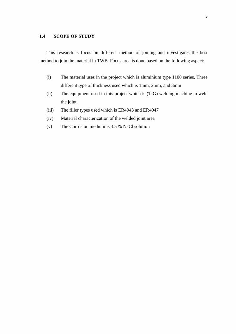
1.4 SCOPE OF STUDY
This research is focus on different method of joining and investigates the best
method to join the material in TWB. Focus area is done based on the following aspect:
(i) The material uses in the project which is aluminium type 1100 series. Three
different type of thickness used which is 1mm, 2mm, and 3mm
(ii) The equipment used in this project which is (TIG) welding machine to weld
the joint.
(iii) The filler types used which is ER4043 and ER4047
(iv) Material characterization of the welded joint area
(v) The Corrosion medium is 3.5 % NaCl solution
4
CHAPTER 2
LITERATURE REVIEW
2.1 INTRODUCTION OF TAILOR WELDED BLANK (TWB)
In several industries such as automotive and aerospace industries, the
lightweight and cost effective product with exceptional performance is crucially needed
in order to be competitive. To fulfil that needed, TWB is some kind of method that
meets all those important element of lightweight and cost effective product with
exceptional performance. Generally, the TWB concept is to customize the sheet metal
thickness and grade at different location within the same sheet (Kinsey, 2010). Some
critical parts of the sheet metal blank need thicker or stronger material (Chan, 2003).
Beside to reduce the weight, the TWB also give advantage for increasing the
local stiffness. It is some kind like new process and new concept of manufacturing.
Normally the process of creating the structural and skin component for vehicle, sheet
metal is used due to superior strength to weight ratio compared with bulk material
products. To assemble the sheet metal with various component traditionally, individual
sheet metal parts are form and then subsequently welded. In TWB, multiple sheet
metals are seam welded or bond together prior to deformation process, thus requiring
only one forming operation. The multiple sheets could be the material within difference
in the thickness, grade, or coating of the material for example galvanized versus none
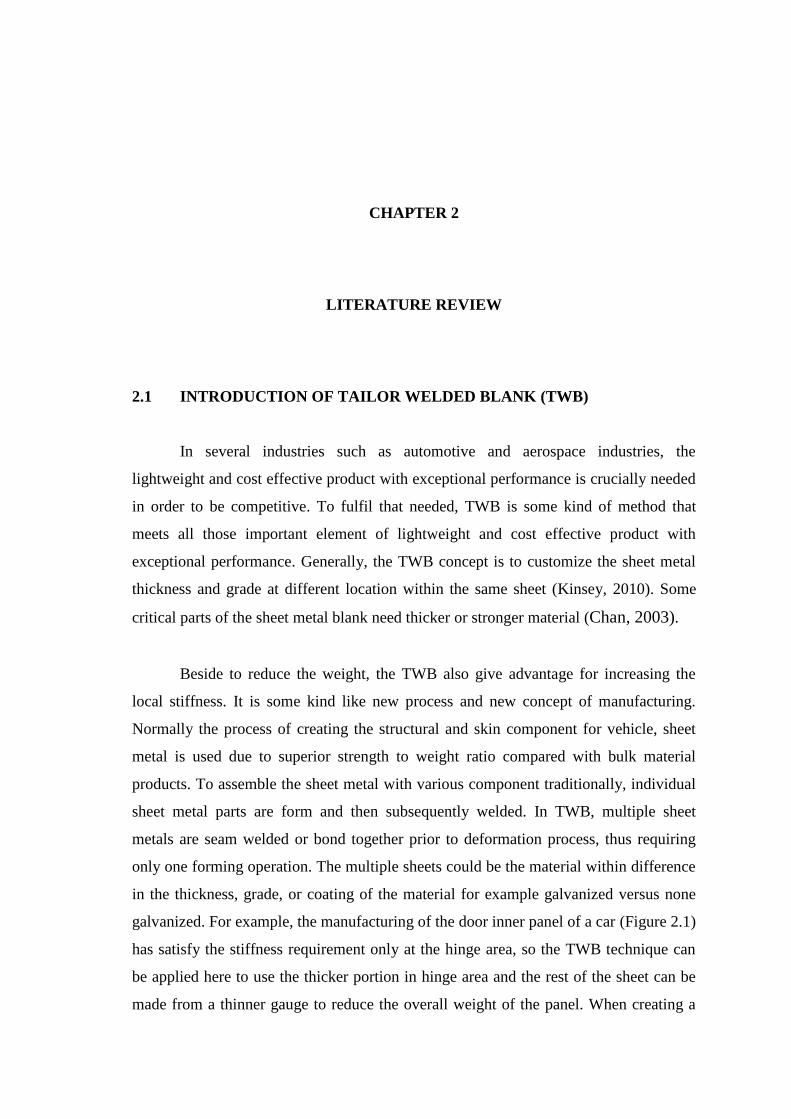
galvanized. For example, the manufacturing of the door inner panel of a car (Figure 2.1)
has satisfy the stiffness requirement only at the hinge area, so the TWB technique can
be applied here to use the thicker portion in hinge area and the rest of the sheet can be
made from a thinner gauge to reduce the overall weight of the panel. When creating a
5
tailor welded blank, designers are able to tailor, hence the name, the location in the
blank where specific material properties are desired. Forming of TWB is challenging
due to a significant reduction of formability associated with this type of blank. First,
material property changes in the heat-affected zone of the weld decrease the potential
strain in the material prior to tearing failure. The thinner part of TWB maybe undergoes
deformation than the thicker part which is stronger material in the forming area. The
main advantage of this method is the opportunity to place the optimum steel thickness
and strength where they are really needed. Not only that, this method also give
advantage in weight saving and with no reinforcement. TWB is a new technology that
allows the designer or engineer to create the something new in automotive technology
in order to reduce component weight and the number of component in a structure
without compromising the final strength, stiffness and durability of the component
(Khairi, 2007). For automotive industry, the Tailor welded method give the advantage
in:
(i) Fewer parts
(ii) Reduce design and development time
(iii) Reduce material use
(iv) Weight reduction
(v) Improve dimensional accuracy
Figure 2.1: View of current and potential automotive tailor welded blank
applications
Source: www.twi.co.uk, 2013
6
This joining of various sheets into a single blank that makes the automobile
designers to tailor the location in the blank where material properties are located
leading to reduced weight, improved part stiffness, and lower manufacturing costs due
to elimination of process dies and reduced scrap.
2.1.1 Similar material of TWB
Nowadays, TWB application is quite widely used, especially in the fields of use
of metal materials such as transportation industries.TWB with blanks of similar
materials and dissimilar thicknesses have been introduced in order to reduce cost. It is
widely use in application that require different strength at different section and proper
weight distribution. Some critical parts of the sheet metal blank need thicker material
and that why the different thickness joining are needed (Chan, 2003). Resulting from
that, it is not only reducing the weight but also did increasing the local stiffness of the
blanks. This change in thickness creates a discontinuity in the TWB that alters the stress
state and consequently the strain that occur during forming (Kinsey, 2010). By
decreasing the thickness of mismatch the weld line movement has reduces since the
stress concentration is the one responsible for failures in the transition zone.
The thickness ratio in forming the TWB is quite important. Every different
thickness ratio has its own effect to the formability of TWB. According to
K.Narasimhan cited in his journal, the thinner blank did give the contribution to the
plastic deformation increases as the thickness ratio increase. The thinner blank will
dominate the overall deformation behaviour for higher thickness ratios.
2.2 Welding Process
To joining the part in TWB welding is the best method. Welding is a permanent
type of joining. Welding is a fabrication technique which done by melting the work
piece until it form the melting pool and adding the filler onto it and let it joint together
with the melting pool and cools to become strong joint. Today there a lot of welding
process available such as TIG, MIG, Fusion welding, laser beam welding and many
more.

7
2.2.1 Tungsten Inert Gas Welding (TIG)
There are several types of welding to joint dissimilar material or thickness. TIG
is one of those. TIGs use a non-consumable electrode made of tungsten. Principally,
TIG welding is an electric arc welding process using an electric arc as fusion energy
burning between the work piece and the tungsten electrode. During the welding process,
the electrode, the arc and the weld pool are protected against the damaging effects of
the atmospheric air by an inert shielding gas. Filler metal is added to the weld pool from
a separate rod or wire. The filler metal will be melted by the heat of the arc. Inert gas is
the types of gas which is does not combine with others element as same as inactive gas.
Commonly Argon and helium or mixtures of both has been use as gasses for shielding
(Larry, 2012). Argon gas is more preferred because of its excellent in providing arc
stability and having a cleaning action in certain materials. Mostly, the TIGs welding
have been use to weld thin section of stainless steel, and non-ferrous metal such as
aluminium. It can also weld many dissimilar metals together. This kind of welding has a
large area of application due to its advantages which is;
(i) Provides a concentrated heating of the work piece
(ii) Provides an effective protection of the weld pool by an inert shielding gas
(iii) Can be independent of filler material
(iv) The filler materials do not need to be finely prepared if only the alloying is
all right
(v) There is no need for after treatment of the weld as no slag or spatter are
produced
(vi) Places of difficult access can be welded
2.2.2 Metal Inert Gas Welding (MIG)
Other type of welding to join the material in TWB is MIG welding. This kind of
welding is applied commonly due to its effectiveness to weld variety of materials,
ferrous and non ferrous (Larry, 2012). MIG welding use a small diameter of electrode
wire also known as filler which has been fed continuously into the arc from a coil. As a
result, it can produce a quick and neat weld at the joint. Generally, MIG welding is an
8
arc welding process, in which the weld is shielded by an external gas such as Argon,
helium, CO2, argon + Oxygen or other gas mixtures. The electrode wire or filler is
consumable and made from chemical composition similar to that parent material supply
from a spool to the arc zone. The melting process will occurred as the arc heat did melt
the filler and the edges of the work pieces. The fused electrode material is supplied to
the surfaces of the work pieces, fills the weld pool and forms joint. The selection of the
filler crucially and proper selection is required to produce a weld deposit with these
basic objectives:
(i) A deposit closely matching the mechanical properties and physical
characteristic of the base metal.
(ii) A sound weld deposit, free of discontinuities
The selection of the welding electrode should be based principally upon
matching the mechanical properties and the physical characteristics of the base metal.
MIG welding is a technique that has a lot of advantage such as following:
(i) Continuous weld may be produced
(ii) High level of operator’s skill is not required
(iii) Slag removal is not required (no slag)
2.2.3 Filler Types
Filler is a component used during welding process by adding it onto the weld
pool throughout welding duration. There are four types identified as covered electrodes,
bare electrode wire or rod, tubular electrode wire, and welding fluxes. Filler ER 4043
and ER 4047 was widely use during aluminium alloy weld. The major different
between these two types of filler is the amount of silicon where the ER4043 filler
contain 4.5 – 6.0 % while for filler ER4047 contain 11.0 – 13.0 % silicon. Different
filler types will give different corrosion rate on the fusion zone of the welded joint

9
2.2.4 Joining Design
There are several types of design during joining process. The most common
used are butt join (Figure 2.2) and lap joint (Figure 2.3).
Figure 2.2: Butt joint (a), Lap joint (b)
Source: Junglan, 2012
Butt joint is a joint type which two separated members are joined at the same
plane at the edge of the material. It is the simplest joint. For thicker material, a gap
between the materials is needed. This design of joint is more application in
manufacturing pressure vessels, piping, tanks and other applications that require a
smooth weld face. Lap joint applied by overlapping items that do not lie directly on top
of one another and a fillet weld is deposited along the joint. Lap joint normally used to
weld thin section.
In order to join the various sheets into single blank in TWB, the permanent joint
is the type of the join that has been determined to apply. Permanent joint is the join type
that is to stay put and there are two types of it, which is welding and riveting. To
perform the permanent joint in TWBs the method to use is welding.
Generally, welding means a process of joining two or more metallic material by
using a fused metal also known as welding rod upon the joining by raising the
temperature of their surfaces or edges to the fusion temperature. But nowadays the
function of the welding are wide and various, based on American Welding Society’s
(a) (b)
10
(AWS), welding can be describe as a localized coalescence of metal or non-metals
produced either by heating the materials to required welding temperature, with or
without the application of pressure, or by the application of pressure alone, and with or
without the use of filler materials (Larry, 2012). Coalescence means the fusion or
growing together of the grain structure of the materials being welded. Nowadays, there
are a lot of welding types that have been used for industry. These four types are the
most commonly used in the industry which is MIG welding, Arc welding, Gas welding
and TIG welding. For TWB, several types of welding have been used as it meets the
requirement. The types of welding that commonly use nowadays are such as TIG, MIG,
Shield metal arc welding, and laser beam welding.
2.3 MATERIALS
In TWB, there are several materials that have been used to meet the demands for
lightweight for manufacturing. The lightweight metal alloys materials are chosen in
these industries because of their low density and high specific strength alongside the
special features such as corrosion resistance, dimensional stability and many more.
Metal alloys also preferred due to environment concerns, government regulations and
consumer demands (Kinsey, 2010).
2.3.1 Aluminium
Aluminium is known as lightweight material. Aluminium is available in
abundance on the earth’s crust, largely in form of cryolite or bauxite. Aluminium has a
unique combination of attractive properties such as low weight, high strength, superior
malleability, easy machining, excellent corrosion resistance and good thermal and
electrical conductivity (Jacobs, 2007). The melting point for aluminium is 660.32 °C.
The strength of the Aluminium alloy can be increase by alloying it with manganese,
silicon, cooper, magnesium, zinc, and many more (Kinsey, 2010). By applied different
alloying element and heat treatment, aluminium can be dividing into several groups.
That group using four digit number starting from 1XXX to 8XXX. The 1XXX series of
aluminium has low yield strength, while the 5XXX and 6XXX series have yield
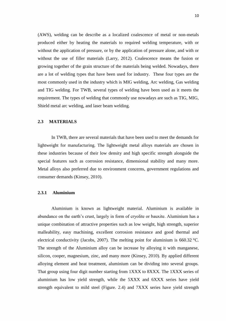
strength equivalent to mild steel (Figure. 2.4) and 7XXX series have yield strength
11
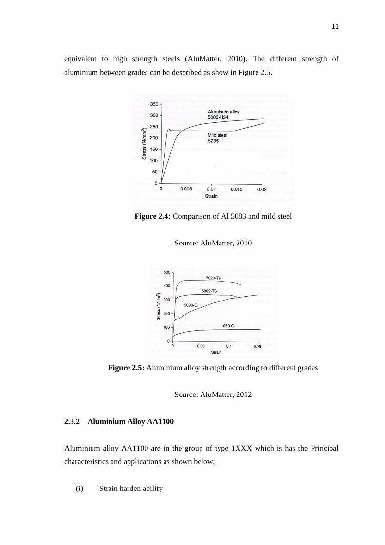
equivalent to high strength steels (AluMatter, 2010). The different strength of
aluminium between grades can be described as show in Figure 2.5.
Figure 2.4: Comparison of Al 5083 and mild steel
Source: AluMatter, 2010
Figure 2.5: Aluminium alloy strength according to different grades
Source: AluMatter, 2012
2.3.2 Aluminium Alloy AA1100
Aluminium alloy AA1100 are in the group of type 1XXX which is has the Principal
characteristics and applications as shown below;
(i) Strain harden ability
12
(ii) High formability, corrosion resistance, and electrical conductivity
(iii) Electrical and chemical applications
(iv) Typical ultimate tensile strength range: 10 to 27 ksi (70 to 185 MPa)
These type of aluminium consist almost 99 % aluminium properties. It is also
non heat treatable and also known as commercially pure aluminium. The main
important of the aluminium alloy AA1100 type is high corrosion resistance. AA100
also display excellent forming, welding and finishing characteristic. It has been widely
used in for packaging chemical equipment, tank car or truck bodies and aircraft
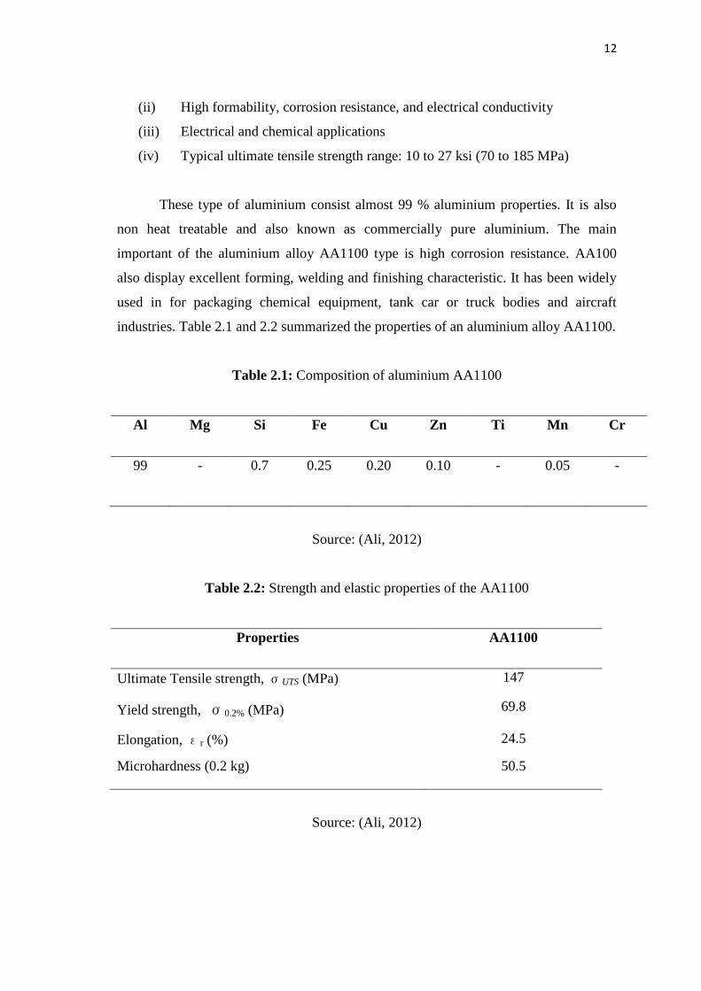
industries. Table 2.1 and 2.2 summarized the properties of an aluminium alloy AA1100.
Table 2.1: Composition of aluminium AA1100
Al Mg Si Fe Cu Zn Ti Mn Cr
99
-
0.7
0.25 0.20
0.10 - 0.05 -
Source: (Ali, 2012)
Table 2.2: Strength and elastic properties of the AA1100
Properties AA1100
Ultimate Tensile strength, σUTS (MPa) 147
Yield strength, σ0.2% (MPa) 69.8
Elongation, εr (%) 24.5
Microhardness (0.2 kg) 50.5
Source: (Ali, 2012)