Embed Size (px)
Citation preview
Effect of Depth and Flange to Web Thickness
Ratio on Structural Behaviour of Corrugated RC
Section Used in Arch Bridge
Chong Yong Ong, Jia Bin Yeo, and Kok Keong Choong School of Civil Engineering, Universiti Sains Malaysia, Penang, Malaysia
Email: [email protected]
Mirzakhid Miralimov Road Construction Department, Tashkent Automobile and Road Institute, Tashkent, Uzbekistan
Email: [email protected]
Abstract—Arch structures is one of the oldest structural
form in bridge engineering. Due to its surprisingly
durability and aesthetic value, it is widely used as crossing
over valleys and rivers nowadays. Closed spandrel arch
bridge is one type of arch bridges that have been produced
using precast concrete technology since 1965. Various cross-
sectional shapes for precast concrete bridge have been
proposed. Corrugated shape is a relatively new section
which was introduced in 2008 in Malaysia. In this paper, the
effect of depth, flange to web thickness ratio and slenderness
ratio on structural behavior of this new corrugated arch
section is presented. Computational analysis is carried out
using analysis software PLAXIS and LUSAS. A total of 25
models with various flange to web thickness ratio and
overall depth is proposed. The clear rise and clear span of
the bridge is 5.8m and 20.6m, respectively. It was found that
high slenderness ratio of the corrugated section result in
lower stress in the section at crown but higher stress in the
section at haunch. The flange to web thickness ratio
contributes insignificantly to the maximum stress resulted
on the corrugated section.
Index Terms—precast concrete closed spandrel arch bridge,
corrugated section, flange to web thickness ratio,
slenderness ratio
I. INTRODUCTION
Countless arches have been developed with
outstanding performance as early as 3000 B.C. by the
ancient Egyptians [1], 800 B.C. by the Assyrians [2], 100
B.C. by the Romans and 610 A.D by the Chinese [3].
Arch structures are widely used for bridge structures due
to its aesthetic value and durability. Arch structures have
the advantages of transferring transverse load via axial
action and resist compressive axial force effectively. As a
result, section of arch structure can be more efficiently
utilized. Such more efficient usage of material of section
will lead to relative lighter section in comparison with
bridge structures without curvature such as girder bridges.
Manusript received July 7, 2015; revised September 27, 2015.
Due to the existence of curvature in arch structure, the
associated construction process will be more complicated
than straight members. In comparison with cast-in-situ
method, the use of precast method will lead to better
control of arch segments especially the curvature of the
arch segments. With the advancement in precast concrete
technology, precast concrete arch bridges have been
widely used for short to medium span bridges from
25.6m to 50m.
This study focuses on closed spandrel precast concrete
arch bridges. Various cross-sectional shapes for precast
concrete bridge have been proposed. Among the variety
of cross-sectional shapes, corrugated shape is a relatively
new section. It has the following advantages: unique
aesthetic value, high stiffness to self-weight ratio, 40%
lighter compared with solid rectangular section and
ability to span beyond limit of 25.6m (possibly up to 50m
for short to medium span) [4], [5]. Patent has been
granted for this new corrugated arch segment in 2008 [6].
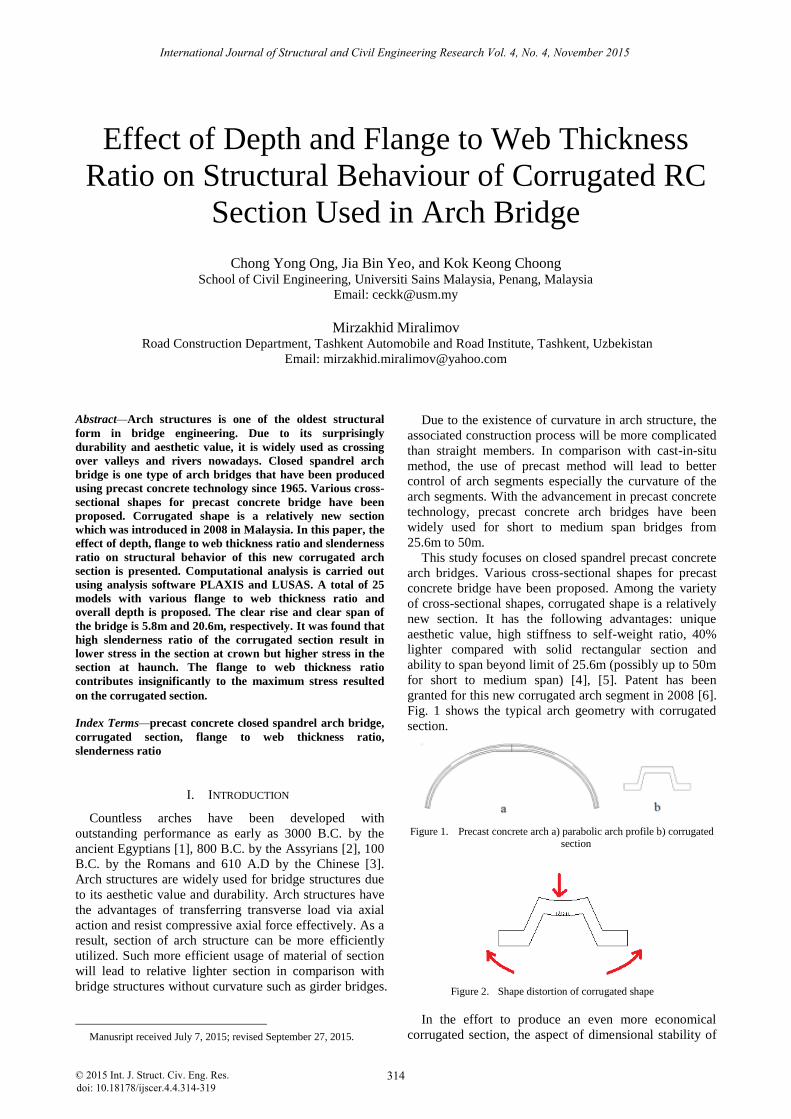
Fig. 1 shows the typical arch geometry with corrugated
section.
Figure 2. Shape distortion of corrugated shape
In the effort to produce an even more economical
corrugated section, the aspect of dimensional stability of
314
International Journal of Structural and Civil Engineering Research Vol. 4, No. 4, November 2015
© 2015 Int. J. Struct. Civ. Eng. Res.doi: 10.18178/ijscer.4.4.314-319
Figure 1. Precast concrete arch a) parabolic arch profile b) corrugated section

the sectional shape needs to be considered. In comparison
with solid and closed cross-sectional shape, corrugated
shape suffers from the problem of shape distortion as
shown in Fig. 2. This is due to the fact that corrugated
shape is an open section.
As arch bridge is typically used to span a wide clear
span, it is crucial that efficient sectional shapes to be used.
In this way, the self-weight of the whole bridge can be
reduced. This will then lead to more economical way of
construction as machinery with lower capacity can be
used.
Proper ratio of flange to web thickness should be used
in order to ensure the rigidity of the sectional shape.
When considering the ratio of flange to web thickness,
the overall slenderness of the arch segment should also be
considered. Slenderness ratio is defined as:
𝑆𝑙𝑒𝑛𝑑𝑒𝑟𝑛𝑒𝑠𝑠 𝑅𝑎𝑡𝑖𝑜 =𝐿
𝐷 (1)
where, L = Length of actual arch segment
D = Overall depth of the section
The rigidity of the cross-section under transverse
loading acting on the arch segment will lead to a
secondary effect. Such secondary effect will lead to crack
developing in the longitudinal direction of the arch
segment. This secondary effect will impede the structural
capacity of the concrete and this may result in structural
failure of the concrete bridge which is an unfavourable
condition. Therefore this study is needed to determine the
influence of section parameter on the behaviour of the
corrugated section.
Figure 3. Notation used for the corrugated section
II. COMPUTATIONAL LINEAR ANALYSIS
Linear analysis using program PLAXIS and LUSAS
are carried out to analyse and compare these closed
spandrel arch with corrugated section in terms of
structural capacity under different loading with different
ratio of flange to web thickness. Fig. 3 shows the notation
used for the corrugated section. The notation ‘d’ indicates
the overall depth of the section while ‘tf’ indicates the
thickness of the flange.
A. Model of Arch Structure
The arch section is designed as a single element with
both ends pinned. Different flange to web thickness ratios
of the corrugated section models is considered. In this
study, the web thickness is fixed as 100mm. The flange
thickness and overall depth of the corrugated section is
manipulated as shown in Table I. The flange thickness
are divided into five categories – A to E. In this study, the
total longitudinal length of the corrugated arch is fixed at
25.63m. The slenderness ratio shown in Table II is
defined as the ratio of length to depth.
TABLE I. MODEL WITH VARIOUS FLANGE THICKNESS AND OVERALL
DEPTH
Category
Flange
thickness,
tf (mm)
Ratio of
flange to web
thickness
Model
Overall
Depth, d
(mm)
A1 475
A2 500
A 135 1.35 A3 525
A4 550
A5 575
B1 475
B2 500
B 140 1.4 B3 525
B4 550
B5 575
C1 475
C2 500
C 145 1.45 C3 525
C4 550
C5 575
D1 475
D2 500
D 150 1.5 D3 525
D4 550
D5 575
E1 475
E2 500
E 155 1.55 E3 525
E4 550
E5 575
TABLE II. VARIOUS SLENDERNESS RATIOS
Overall Depth (mm) Slenderness Ratio
475 53.97
500 51.27
525 48.83
550 46.61
575 44.58
B. Load Cases
This corrugated closed spandrel arch bridge is
designed to withstand the loading as specified in BS 5400:
Part 1 & 2 (1978) [7], [8], BD 31/01 [9] and BD 37/01
[10] for a design period of 120 years. Primary live loads
considered for the design of the bridge are as follows: (a)
HA-UDL + HA-KEL and (b) HB-45 unit guided at the
centerline of the deck. The dead load of the precast arch
panel is resisted initially by a three-pinned arch system.
Once the crown is connected, the ring of the precast arch
panel acts as a two-pinned arch system to resist loads.
They are modelled accordingly in design and analysis for
all possible loading stages.
C. PLAXIS Model
Generally, Plaxis Software is used in the linear
analysis of precast concrete arch bridge. The arch is
315
International Journal of Structural and Civil Engineering Research Vol. 4, No. 4, November 2015
© 2015 Int. J. Struct. Civ. Eng. Res.
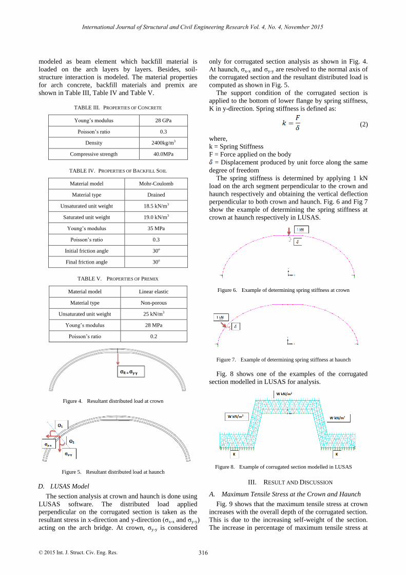
modeled as beam element which backfill material is
loaded on the arch layers by layers. Besides, soil-
structure interaction is modeled. The material properties
for arch concrete, backfill materials and premix are
shown in Table III, Table IV and Table V.
TABLE III. PROPERTIES OF CONCRETE
Young’s modulus 28 GPa
Poisson’s ratio 0.3
Density 2400kg/m3
Compressive strength 40.0MPa
TABLE IV. PROPERTIES OF BACKFILL SOIL
Material model Mohr-Coulomb
Material type Drained
Unsaturated unit weight 18.5 kN/m3
Saturated unit weight 19.0 kN/m3
Young’s modulus 35 MPa
Poisson’s ratio 0.3
Initial friction angle 30o
Final friction angle 30o
TABLE V. PROPERTIES OF PREMIX
Material model Linear elastic
Material type Non-porous
Unsaturated unit weight 25 kN/m3
Young’s modulus 28 MPa
Poisson’s ratio 0.2
D. LUSAS Model
The section analysis at crown and haunch is done using
LUSAS software. The distributed load applied
perpendicular on the corrugated section is taken as the
resultant stress in x-direction and y-direction (σx-x and σy-y)
acting on the arch bridge. At crown, σy-y is considered
only for corrugated section analysis as shown in Fig. 4.
At haunch, σx-x and σy-y are resolved to the normal axis of
the corrugated section and the resultant distributed load is
computed as shown in Fig. 5.
The support condition of the corrugated section is
applied to the bottom of lower flange by spring stiffness,
K in y-direction. Spring stiffness is defined as:
(2)
where,
k = Spring Stiffness
F = Force applied on the body
= Displacement produced by unit force along the same
degree of freedom
The spring stiffness is determined by applying 1 kN
load on the arch segment perpendicular to the crown and
haunch respectively and obtaining the vertical deflection
perpendicular to both crown and haunch. Fig. 6 and Fig 7
show the example of determining the spring stiffness at
crown at haunch respectively in LUSAS.
Fig. 8 shows one of the examples of the corrugated
section modelled in LUSAS for analysis.
III. RESULT AND DISCUSSION
A. Maximum Tensile Stress at the Crown and Haunch
Fig. 9 shows that the maximum tensile stress at crown
increases with the overall depth of the corrugated section.
This is due to the increasing self-weight of the section.
The increase in percentage of maximum tensile stress at
316
International Journal of Structural and Civil Engineering Research Vol. 4, No. 4, November 2015
© 2015 Int. J. Struct. Civ. Eng. Res.
Figure 4. Resultant distributed load at crown
Figure 5. Resultant distributed load at haunch
Figure 6. Example of determining spring stiffness at crown
Figure 7. Example of determining spring stiffness at haunch
Figure 8. Example of corrugated section modelled in LUSAS
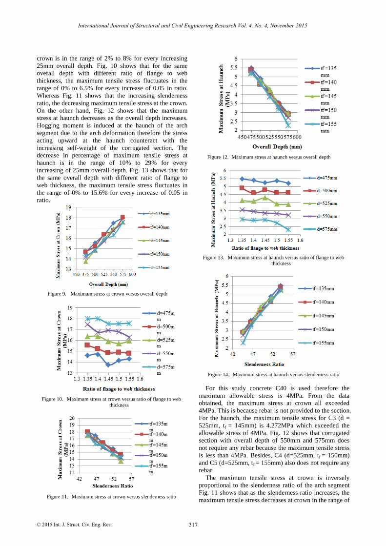
crown is in the range of 2% to 8% for every increasing
25mm overall depth. Fig. 10 shows that for the same
overall depth with different ratio of flange to web
thickness, the maximum tensile stress fluctuates in the
range of 0% to 6.5% for every increase of 0.05 in ratio.
Whereas Fig. 11 shows that the increasing slenderness
ratio, the decreasing maximum tensile stress at the crown.
On the other hand, Fig. 12 shows that the maximum
stress at haunch decreases as the overall depth increases.
Hogging moment is induced at the haunch of the arch
segment due to the arch deformation therefore the stress
acting upward at the haunch counteract with the
increasing self-weight of the corrugated section. The
decrease in percentage of maximum tensile stress at
haunch is in the range of 10% to 29% for every
increasing of 25mm overall depth. Fig. 13 shows that for
the same overall depth with different ratio of flange to
web thickness, the maximum tensile stress fluctuates in
the range of 0% to 15.6% for every increase of 0.05 in
ratio.
Figure 9. Maximum stress at crown versus overall depth
Figure 10. Maximum stress at crown versus ratio of flange to web
thickness
Figure 11. Maximum stress at crown versus slenderness ratio
Figure 12. Maximum stress at haunch versus overall depth
Figure 13. Maximum stress at haunch versus ratio of flange to web thickness
Figure 14. Maximum stress at haunch versus slenderness ratio
For this study concrete C40 is used therefore the
maximum allowable stress is 4MPa. From the data
obtained, the maximum stress at crown all exceeded
4MPa. This is because rebar is not provided to the section.
For the haunch, the maximum tensile stress for C3 (d =
525mm, tf = 145mm) is 4.272MPa which exceeded the
allowable stress of 4MPa. Fig. 12 shows that corrugated
section with overall depth of 550mm and 575mm does
not require any rebar because the maximum tensile stress
is less than 4MPa. Besides, C4 (d=525mm, tf = 150mm)
and C5 (d=525mm, tf = 155mm) also does not require any
rebar.
The maximum tensile stress at crown is inversely
proportional to the slenderness ratio of the arch segment
Fig. 11 shows that as the slenderness ratio increases, the
maximum tensile stress decreases at crown in the range of
317
International Journal of Structural and Civil Engineering Research Vol. 4, No. 4, November 2015
© 2015 Int. J. Struct. Civ. Eng. Res.
2.2% to 8%. On the other hand, the maximum tensile
stress at haunch is directly proportional to the slenderness
ratio of the arch segment. Fig. 14 shows that as the
slenderness ratio increases, the maximum tensile stress
increases in the range of 10% to 29%.
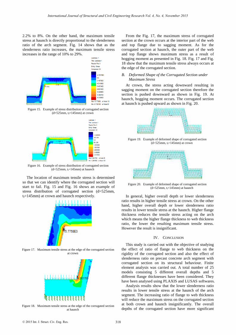
Figure 15. Example of stress distribution of corrugated section (d=525mm, tf=145mm) at crown
Figure 16. Example of stress distribution of corrugated section
(d=525mm, tf=145mm) at haunch
The location of maximum tensile stress is determined
so that we can identify where the corrugated section will
start to fail. Fig. 15 and Fig. 16 shows an example of
stress distribution of corrugated section (d=525mm,
tf=145mm) at crown and haunch respectively.
From the Fig. 17, the maximum stress of corrugated
section at the crown occurs at the interior part of the web
and top flange due to sagging moment. As for the
corrugated section at haunch, the outer part of the web
and top flange shows maximum stress as a result of
hogging moment as presented in Fig. 18. Fig. 17 and Fig.
18 show that the maximum tensile stress always occurs at
the edge of the corrugated section.
B. Deformed Shape of the Corrugated Section under
Maximum Stress
At crown, the stress acting downward resulting in
sagging moment on the corrugated section therefore the
section is pushed downward as shown in Fig. 19. At
haunch, hogging moment occurs. The corrugated section
at haunch is pushed upward as shown in Fig. 20.
Figure 19. Example of deformed shape of corrugated section (d=525mm, tf=145mm) at crown
Figure 20. Example of deformed shape of corrugated section (d=525mm, tf=145mm) at haunch
In general, higher overall depth or lower slenderness
ratio results in higher tensile stress at crown. On the other
hand, higher overall depth or lower slenderness ratio
results in lower tensile stress at the haunch. Higher flange
thickness reduces the tensile stress acting on the arch
which means the higher flange thickness to web thickness
ratio, the lower the resulting maximum tensile stress.
However the result is insignificant.
IV. CONCLUSION
This study is carried out with the objective of studying
the effect of ratio of flange to web thickness on the
rigidity of the corrugated section and also the effect of
slenderness ratio on precast concrete arch segment with
corrugated section on its structural behaviour. Finite
element analysis was carried out. A total number of 25
models consisting 5 different overall depths and 5
different flange thicknesses have been considered. They
have been analysed using PLAXIS and LUSAS softwares.
Analysis results show that the lower slenderness ratio
results in lower tensile stress at the haunch of the arch
segment. The increasing ratio of flange to web thickness
will reduce the maximum stress on the corrugated section
at both crown and haunch insignificantly. The overall
depths of the corrugated section have more significant
318
International Journal of Structural and Civil Engineering Research Vol. 4, No. 4, November 2015
© 2015 Int. J. Struct. Civ. Eng. Res.
Figure 17. Maximum tensile stress at the edge of the corrugated section at crown
Figure 18. Maximum tensile stress at the edge of the corrugated section at haunch
effect on the structural behaviour of the corrugated arch.
The research shows that higher overall depth increases
the bending moment, axial force and shear force but
reduces the vertical displacement resulting on the arch
segment. High slenderness ratio with constant arch length
reduces the maximum tensile stress on the corrugated
section at the crown while high slenderness ratio with
constant arch length increases the maximum tensile stress
on the corrugated section at the haunch.
REFERENCES
[1] J. Bernini, N. Fitzsimons, and W. Heierli, “Overfilled precast
concrete arch bridge structures,” in Proc. 16th Congress of International Association for Bridge and Structural Engineering,
Lucerne, 2000, pp. 380-387.
[2] W. R. Gray, The Builders: Marvels of Engineering. Overcoming Distance with Bridges, Washington DC: The Book Division,
National Geographic Society, 1992.
[4] C. Y. Ong, K. K. Choong, and G. E. Tan, “CAFEO 32-full paper
development of conference of ASEAN federation engineering of organisation,” in Proc. Conference of ASEAN Federation
Engineering of Organisation, Yangon, Myanmar, 2014, pp. 66.
[5] G. E. Tan, T. B. Ong, K. K. Choong, and C. Y. Ong, “A new form of precast closed spandrel arch bridge system,” in Proc. 7th
International Conferences on Arch Bridges, Trogir-Split, Croatia,
2013, pp. 195-202. [6] “Corrugated arch elements of culvert, bridge, crossing or shelter
and a construction thereof,” Malaysian Patent, MY-142912-A.
2008. [7] Steel, Concrete and Composite Bridges, General Statement,
British Standards Institute, BS5400-1:1978.
[8] Steel, Concrete and Composite Bridges, Specification for Loads, British Standards Institute, BS5400-2:1978.
[9] Highways Agency (UK), BD31/01, Departmental Standards, The
Design of Buried Concrete Box and Portal Frame Structure, Department of Transport, Highway and Traffic, November 2001.
[10] Highways Agency (UK), BD37/01, Departmental Standards, Loads for Highway Bridges, Design Manual for Roads and
Bridges, Department of Transport, Highway and Traffic, 2001.
Chong Yong Ong was born on 1st February
1988 in Sungai Petani, Kedah, Malaysia. He
graduated with Bachelor of Engineering (Honours) in Civil Engineering in Universiti
Sains Malaysia, Nibong Tebal, Pulau Pinang,
Malaysia in 2012. After his degree graduation, he worked as a
design engineer in precast concrete
engineering field, especially in Precast Concrete Retaining Wall, Precast Concrete
Sheetpile Wall, Precast Open Spandrel Arch Bridge and Precast Closed
Spandrel Arch Bridge. Currently, he is a Ph.D candidate specializing in Precast Arch Bridge Engineering in Universiti Sains Malaysia,
Engineering Campus under the supervision of Assoc. Prof. Dr Choong
Kok Keong. During his Ph.D study, he has published few publications in international and local journals and conference proceedings that are
related to precast engineering. Besides, he also actively involves in
Graduate and Student (G&S) The Institution of Engineers, Malaysia (Penang Branch) as one of the committee member.
Jia Bin Yeo is currently undergraduate student of Bachelor of Engineering (Civil
Engineering) program in Universiti Sains
Malaysia, Nibong Tebal, Penang, Malaysia.
Kok Keong Choong is Associate Professor at
School of Civil Engineering, Universiti Sains Malaysia. He is currently the Deputy Dean
(Research) of the School of Civil Engineering.
His research interest includes computational analysis of shell and spatial structures and
computational mechanics.
Mirzakhid Miralimov is Associate Professor
in the Department of Civil Engineering and
Road Construction Department, Tashkent Automobile and Road Institute (TARI),
Uzbekistan. His research interests are
primarily in application of the finite element method (FEM)
in structural and
civil
engineering (roads, bridges and tunnels). He has conducted industrial research/consultancy
works in the areas related to statics, structural
dynamics, design of steel and RC structures of bridges and tunnels. He was
visiting researcher from The World Academy Sciences (TWAS),
Italy -USM Fellowship Programme in the School of Civil Engineering,
USM
from February to April 2015.
319
International Journal of Structural and Civil Engineering Research Vol. 4, No. 4, November 2015
© 2015 Int. J. Struct. Civ. Eng. Res.
[3] P. E. Mondorf, Concrete Bridges: Chapter 10: Arch Bridges, Taylor & Francis Group, 2006.