Embed Size (px)
Citation preview
Adv Syst Sci Appl 2020; 02; 1-19 Published online at https://ijassa.ipu.ru.
Effect of Fiber Orientation and Residual Stresses on the
Structural Performance of Injection Molded Short-Fiber-Reinforced components
Giorgio Ramorino1, Silvia Cecchel1, Giovanna Cornacchia1*
1) DIMI, Department of Industrial and Mechanical Engineering, University of Brescia, via Branze 38, 25123 Brescia, Italy.
E-mail: [email protected].
Abstract: The increasingly need of lightweight structures in different sectors is driving new researches about the substitution of metal with polymeric matrix composite. Objective of this work is to optimize the strength design of short-fiber injection molding manifold block, originally made with brass, with the aid of a three-dimensional flow and structural analysis simulations. These Finite Element Analyses (FEA) were based on orthotropic, linear and elastic models including process-induced residual stresses. Through an appropriate interface, the results of injection molding analysis of 35 wt.% fiber reinforced polyphthalamides (PPA) manifold block are transferred to the structural analysis software. Autodesk Moldlfow software was used to predict the fiber orientation and the in-cavity residual stresses considering the flow kinetics and moulding parameters. The Abaqus interface for Moldflow was used to translate this data into a form that can be used for the structural analysis. Finally, this paper reports some experimental tests carried out on the injection moulded component in order to evaluate the internal burst pressure values. The results not only highlighted the importance of carrying out structural simulations, which consider both the orientation of the glass fibre and the residual stresses given by molding, but also showed the usefulness and accuracy of an integrated CAD-FEA approach. The application on a real case demonstrated good agreement with numerical analysis predictions.
Keywords: moldflow, Abaqus, residual stress, injection moulding, short-fiber-reinforced components, metal replacement
1. INTRODUCTION Nowadays the research of technical solutions to answer at the lightweighting issue connected to emissions reduction, safety and economic targets is constantly increasing [1-3]. Advances in researches concerning the materials choice are required in several field. In this context, it is possible to observe not only substitution of i.e. steel with light alloys [4-8] but ever more frequently, where possible, metal replacement with polymer matrix composites [9-10]. Today, the metal replacement is present in different industrial sectors, i.e., automotive, medical and electronics, where benefits like weight reduction, corrosion resistance and improved weldability can be achieved with low costs [11-16]. In this persistent search of lightness and cost reduction, the use of thermoplastics composite materials is continuously increasing in place of metal parts. The most common method for plastic part manufacturing is injection molding, which is suitable for the mass production of complex short fiber plastic parts with precise dimensions [17]. The properties of plastic materials can vary over a wider range than all other engineering materials and they can be enhanced with the addition of various agents. Fiber reinforced thermoplastics are a category of composite plastics used in technical applications at increasing loads or elevated temperatures, because they have a higher stiffness, strength, and a reduced tendency to creep compared with non-reinforced polymers. For instance, short-fiber-reinforced thermoplastic products obtained by injection molding are currently successfully used in metal replacement applications [18-22]. It is worthwhile to * Corresponding author: [email protected]
2 G. RAMORINO, S. CECCHEL, G. CORNACCHIA
Copyright ©2020 ASSA Adv. in Systems Science and Appl. (2020)
note that the structural performances of these products are greatly affected by the fibers’ orientation state [23-25]. During the filling stage of the injection molding process, the polymer molecules and reinforcing fibers (for fiber-filled polymers) are oriented in a direction influenced by the shear flow. This leads to anisotropy in the mechanical properties of the material. Fiber orientation also causes differential shrinkage in the longitudinal and transverse directions, which can lead to warpage (bending and twisting of a molded part after it has been ejected from the mold and cooled down to ambient temperature). Further, this orientation improves mechanical properties in the fiber direction while reduced the strength in the transverse direction [26-27]. Therefore, the prediction of fiber orientation using Computer-Aided Engineering (CAE) tools is of great importance for the safe design of short-fiber reinforced thermoplastic parts [28-29]. The calculated fiber direction can lead to local mechanical properties, thus allowing precise structural analysis of a moulded component. If a fiber-reinforced material is used to produce the part, the formation of the weld-lines is one of the most significant problems for structural applications due to the potential failure in correspondence of these discontinuities [30-33]. Weld lines occur when two or more flow fronts do not blend completely when they meet in the mould. This happens, for example, when the melts splits as it flows around an obstacle such as a core or pin in the mold cavity or when parts are gated at several points. These necessary features represent discontinuities during the filling of the mold and induce the formation of weld lines with a further potential increase of the damage since these are stressed areas. The quality-reduction factors in the weld line area are highly dependent on the type and content of filling and reinforcing material. The existence of weld-lines will generally reduce the local material strength by greater than fifty percent in glass-reinforced resins due to unfavorable molecular orientation, insufficient bonding and/or formation of a V-notch [34-36]. Therefore, a part containing one or more weld lines that are subjected to a localized structural loading will not perform as well as a component containing no weld-lines. Weld-lines strength can be improved by modifying the geometry of the parts or changing the structure of the mould or adjusting the process parameters such as melt temperature, injection velocity, holding pressure, holding time, and mold temperature. Injection moulding usually induces Residual Processing Stresses (RPS), stored in the components after ejection from the mould and cooling to ambient temperature, which are originated from two main sources: “flow-induced stresses” as well as “thermally and pressure induced stresses” [37-39]. The RPS exist in the moulded part without application of any external load and may affect the plastic component similarly to externally applied load. Thus, especially for structural components, RPS have to be predicted and minimized through the determination of optimum processing conditions. This is particularly important for component with complex geometry like manifold block (Figure 1) where the part is characterized by areas with high thickness. As a result, if the RPS are strong enough to overcome the structural integrity of the part, the component may warp as a consequence of different sources: upon ejection from the mould, after its use for an extended period of time or due to the exposure to relatively high temperatures. Some consequences are poor dimensional stability and potential cracks when external service load is applied due to a strength reduction. It is worthwhile to note that, weld-lines and fiber orientation together with the RPS are the major factors that determine the mechanical strength and stiffness of a moulded component. Design engineers typically solve the problem by applying a generous safety factor to their design, making them thicker than is actually required. Concerning the orientation direction and the degree of orientation of the fibers, it is evident that in areas where fibers are strongly aligned, the material will have higher strength characteristics and higher modulus in that direction, but will be relatively weak with much lower modulus in the perpendicular direction (across the fibers). Because the injection moulding process for short-fiber-reinforced components can cause such great variation in strength and stiffness through the part, the effect of the injection process should be considered in the design of such parts.
EFFECT OF FIBER ORIENTATION AND RESIDUAL STRESSES ON THE STRUCTURAL PERFORMANCE OF INJECTION MOLDED SHORT-FIBER-REINFORCED COMPONENTS 3
Copyright ©2020 ASSA. Adv. in Systems Science and Appl. (2020)
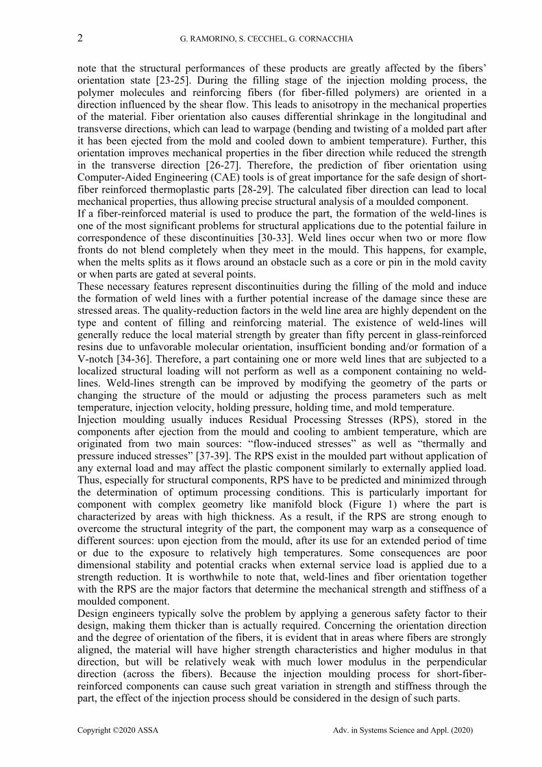
Predicting the position of the weld-lines, as well as the amount of RPS, is useful in the initial stage of product development, in order to avoid modifications on the part and mold design after their manufacturing. Mould filling simulations during the preliminary design step could help to increase the final quality of the component, thanks to the opportunity of improving design and process parameters according to the indications given by simulations. Further advantages are a reduction of the time to market with consequent lower costs. In particular, the use of this new design approach is increasing during the last years and consists in flow simulations and structural analysis employed at the same step of the product development to optimize the strength design. A comparison between this advanced approach and the traditional one, without mould filling simulations, is sketched in Figure1.
Figure 1. Advanced approach: coupling of flow simulations and structural analysis employed to optimize the strength design of component
In the literature, to the best knowledge of the authors, there are few works that try to couple a three-dimensional flow simulations and structural analysis but not based on both orthotropic, linear, elastic simulations and includes RPS [40-42]. A number of researchers have studied the flow induced anisotropy in short-fiber-reinforced composites employing experimental techniques and numerical simulations. However, in these research works, the residual processing stresses (RPS) (stresses that remaining inside the moulded product under the condition of no external loads) are typically neglected in structural analysis where external loads are applied to the components or considered in structural analysis only to determine the optimum processing conditions, residual stress distributions, and final shrinkage and shape of the components. Kulkarni et al. [43] conducted flow and structural analysis on a reinforced square plate composed of composites, by successfully coupling two commercial codes, Moldflow and Ansys. Their results showed that unlike conventional materials, where simple isotropic models can be employed, the simulation with orthotropic configurations are to be employed to gain a better agreement with the experimental results. In particular, load vs. deflection isotropic results are 70% off as compared to experimental results while the othotropic model exhibits a better correlation with more than 92% accuracy. Current Autodesk Moldflow 3D products solve the standard Folgar-Tucker equation for prediction of the fiber orientation distributions. Folgar and Tucker developed a continuum model for a non-dilute suspension based on Jeffery’s model that is used for dilute fiber suspensions, but they included a term that accounts for fiber-fiber interactions which tend to reduce highly aligned orientation states predicted by Jeffery's model for some flow conditions [44]. It was demonstrated that simulation results agree remarkably well with measured microstructural data [45]. A typical example concerns the injection molding of structural components used in hot-water fluid engineering application, where tubes as well as holes have to be integrated in the parts.
4 G. RAMORINO, S. CECCHEL, G. CORNACCHIA
Copyright ©2020 ASSA Adv. in Systems Science and Appl. (2020)
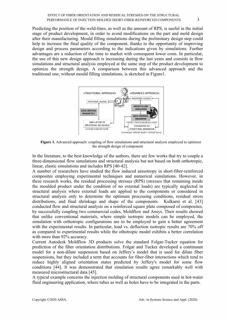
Following these premises, in this experimental work a feasibility study was conducted on a manifold block, a device that regulates fluid flow between pumps and actuators and other components in a hydraulic system. Aim of this analysis is to evaluate the possibility of substitute the brass, material usually employed for this component, with 35 wt.% fiber reinforced polyphthalamides (PPA). In this context, the present paper reports an actual case study where the results of flow simulations and structural analysis were combined to optimize the strength design of a short-fiber-reinforced component. The software Autodesk Moldflow was used to estimate the in-cavity residual stress and the fibers orientation in a moulded component while the structural software Abaqus was used to evaluate how residual stresses and fibers’ orientation state affect the final shape and performance of the product (see Figure 1 – advanced approach). The results of injection molding analysis of 35 wt.% fiber reinforced polyphthalamides (PPAs) manifold block used in hot-water fluid engineering application (Autodesk Moldflow) are transmitted to the structural analysis program (Abaqus). The Abaqus interface for Moldflow is used to translate these data into a form that can be used by Abaqus for the structural analysis. After that, experimental tests are carried out on the injection moulded components in order to evaluate the internal pressure that the component can handle before rupturing called “burst pressure”. The burst strength of the molded manifold block samples is then compared with those predicted by the numerical analysis. The simulations are based on orthotropic, linear, elastic simulations that includes the process residual stress and could play a key role for well-founded predictions in order to optimized part strength, part geometry, mold design and processing conditions.
2. MATERIALS AND METHODS 2.1. Description of the component structure and materials
Figure 2 shows the selected manifold block, component used for hot-water fluid engineering application. The design of either the original brass ((a) and the new metal replaced application composed of 35 wt.% fiber reinforced polyphthalamides (PPA) (b) can be observed. The maximum dimension of the original component is 80x100 mm.
Figure 2. Manifold block used for hot-water fluid engineering application - brass (a) replacement by 35 wt.% fiber reinforced polyphthalamides (PPAs) (b)
The substitution of brass with 35 wt.% fiber reinforced PPA led to a final weight of 190 g, with a weight reduction of about 60% in comparison with the 480 g of the traditional one. The cost analysis reported in figure 2 shows a saving of about 65% respect to the original component.
EFFECT OF FIBER ORIENTATION AND RESIDUAL STRESSES ON THE STRUCTURAL PERFORMANCE OF INJECTION MOLDED SHORT-FIBER-REINFORCED COMPONENTS 5
Copyright ©2020 ASSA. Adv. in Systems Science and Appl. (2020)
2.2. Mould filling analysis
The material used for the injection moulding simulations was Polyphthalamides (PPA) having 35% short Glass Fiber (GF) content (see properties listed in Table 1).
Table 1. Properties of Zytel HTNFG52G35HSLBK011 from DuPont Engineering Polymers
(PPAs+35%GF)
Stress at break (ISO 527) – cond. 180 MPa Tensile modulus (ISO 527) -
cond. 12 GPa
Elongation at break (ISO 527) - cond.
2.7%
HDT (ISO 75-1/-2) 1.8 MPa 285°C Glass transition temp. (ISO
11357-3) 90°C
Melting temperature (ISO 11357-1/-3)
310°C
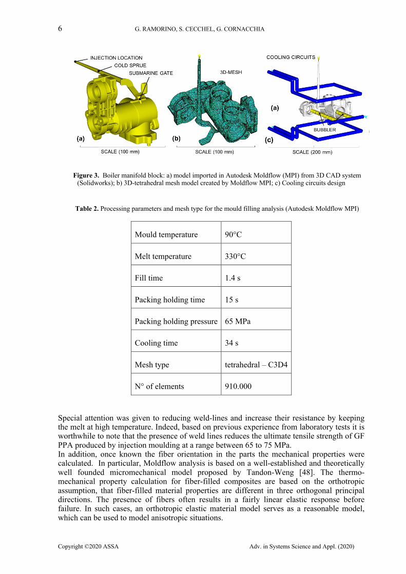
Water Absorption (ISO 62) - 24h. 0.4 % Short-fiber-reinforced PPA material was chosen due to excellent preservation of strength and stiffness at elevated temperatures, great resistance to hydrolysis, high dimensional stability and low warpage [46-47].The mould was designed with a single cavity. The parts were filled with a cold submarine gate and the cavity pressure was controlled via a direct pressure transducer placed in the mould cavity located to the end of the flow path. The injection location, the size of sprue, runners and gate as well as the lay-out of the cooling channels were optimized based on the filling analysis using CAE technology in order to minimize the warpage of the part, decrease cycle times, increase part quality and achieve dimensional stability of the component. More details will be reported in section 3.2. Solid model of the boiler manifold block with the fed system is designed by Solidworks software for the mould filling analysis. Three-dimensional flow simulations based on a solid, tetrahedral finite-element volume mesh were performed with Autodesk Moldflow software. Figure 3a shows the boiler manifold 3D model designed with Solidworks, while Figure 3b reports the three dimensional tetrahedral mesh created by Moldflow MPI. In particular, the finite element mesh employed was tetrahedral – C3D4, having 910’000 elements. The analysis comprised the entire molding process from injection, through mold packing, to component solidification. This kind of simulations also permitted to predict material anisotropy, fibre orientation, in-cavity residual stresses and component warpage /shrinkage. The cooling circuits design, employed to model filling, packing and cooling stages of the injection moulding are reported in Figure 3c. Several iterations were carried out to optimize the injection location and the processing parameters in order to achieve the most balanced flow into the cavity along with uniform pressure drop and flow front temperature. In order to choose the optimum process settings, different conditions affecting injection molding are considered, i.e. injection time, packing holding time and pressure, mold temperature and melt temperature. The detail of optimum processing parameters is summarized in Table 2.
6 G. RAMORINO, S. CECCHEL, G. CORNACCHIA
Copyright ©2020 ASSA Adv. in Systems Science and Appl. (2020)
Figure 3. Boiler manifold block: a) model imported in Autodesk Moldflow (MPI) from 3D CAD system (Solidworks); b) 3D-tetrahedral mesh model created by Moldflow MPI; c) Cooling circuits design
Table 2. Processing parameters and mesh type for the mould filling analysis (Autodesk Moldflow MPI)
Mould temperature 90°C
Melt temperature 330°C
Fill time 1.4 s
Packing holding time 15 s
Packing holding pressure 65 MPa
Cooling time 34 s
Mesh type tetrahedral – C3D4
N° of elements 910.000
Special attention was given to reducing weld-lines and increase their resistance by keeping the melt at high temperature. Indeed, based on previous experience from laboratory tests it is worthwhile to note that the presence of weld lines reduces the ultimate tensile strength of GF PPA produced by injection moulding at a range between 65 to 75 MPa. In addition, once known the fiber orientation in the parts the mechanical properties were calculated. In particular, Moldflow analysis is based on a well-established and theoretically well founded micromechanical model proposed by Tandon-Weng [48]. The thermo-mechanical property calculation for fiber-filled composites are based on the orthotropic assumption, that fiber-filled material properties are different in three orthogonal principal directions. The presence of fibers often results in a fairly linear elastic response before failure. In such cases, an orthotropic elastic material model serves as a reasonable model, which can be used to model anisotropic situations.
EFFECT OF FIBER ORIENTATION AND RESIDUAL STRESSES ON THE STRUCTURAL PERFORMANCE OF INJECTION MOLDED SHORT-FIBER-REINFORCED COMPONENTS 7
Copyright ©2020 ASSA. Adv. in Systems Science and Appl. (2020)
Moldflow Pack analysis also calculated the in-cavity residual stresses developed during the mold filling process along with the material properties required for the orthotropic structural analysis that represent the stresses in the part before it is ejected. The mold physically prevents the material from shrinking while the part is in the cavity, so these results are nearly not affected by other external factors and are a good representation of the real condition.
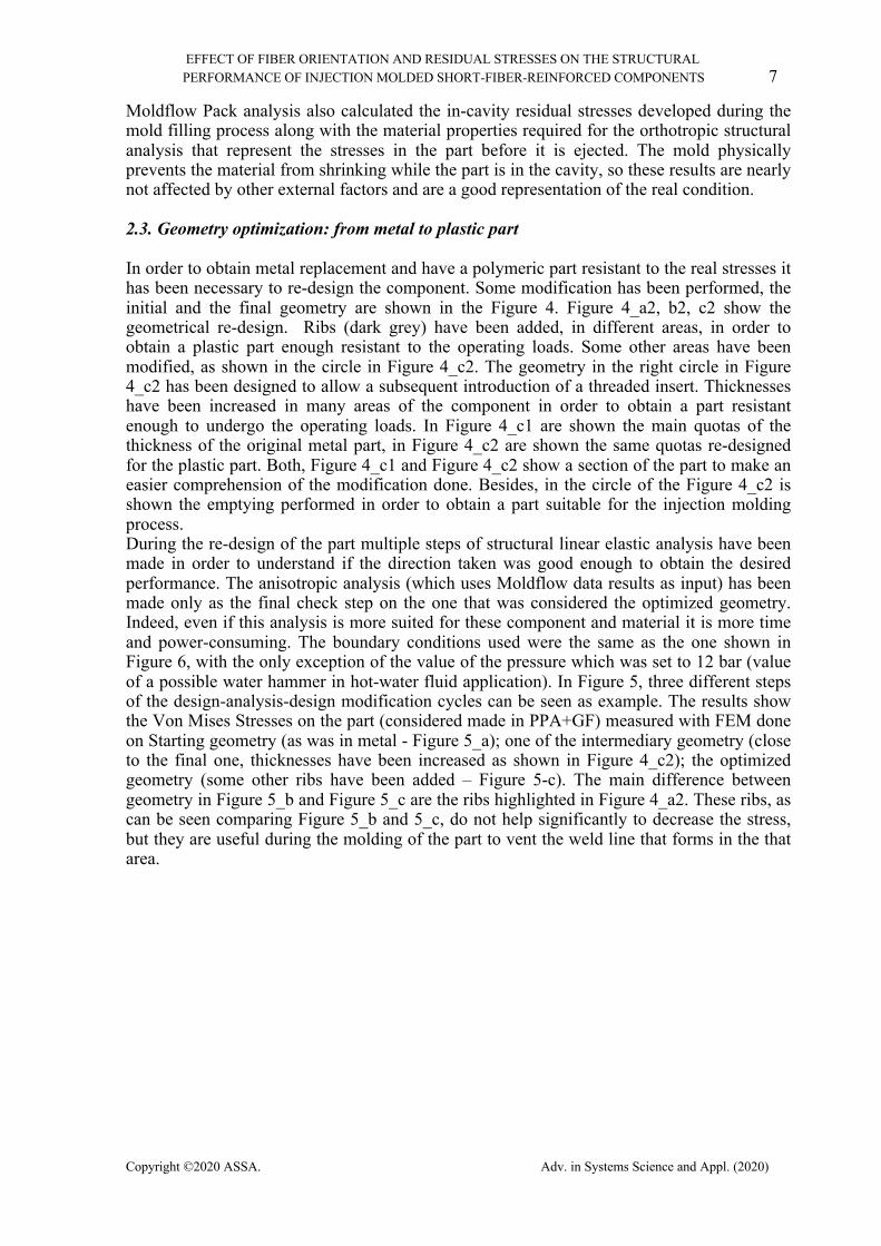
2.3. Geometry optimization: from metal to plastic part
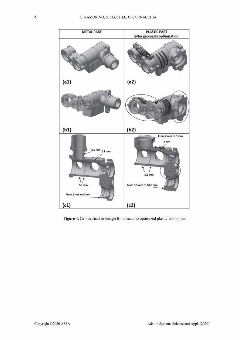
In order to obtain metal replacement and have a polymeric part resistant to the real stresses it has been necessary to re-design the component. Some modification has been performed, the initial and the final geometry are shown in the Figure 4. Figure 4_a2, b2, c2 show the geometrical re-design. Ribs (dark grey) have been added, in different areas, in order to obtain a plastic part enough resistant to the operating loads. Some other areas have been modified, as shown in the circle in Figure 4_c2. The geometry in the right circle in Figure 4_c2 has been designed to allow a subsequent introduction of a threaded insert. Thicknesses have been increased in many areas of the component in order to obtain a part resistant enough to undergo the operating loads. In Figure 4_c1 are shown the main quotas of the thickness of the original metal part, in Figure 4_c2 are shown the same quotas re-designed for the plastic part. Both, Figure 4_c1 and Figure 4_c2 show a section of the part to make an easier comprehension of the modification done. Besides, in the circle of the Figure 4_c2 is shown the emptying performed in order to obtain a part suitable for the injection molding process. During the re-design of the part multiple steps of structural linear elastic analysis have been made in order to understand if the direction taken was good enough to obtain the desired performance. The anisotropic analysis (which uses Moldflow data results as input) has been made only as the final check step on the one that was considered the optimized geometry. Indeed, even if this analysis is more suited for these component and material it is more time and power-consuming. The boundary conditions used were the same as the one shown in Figure 6, with the only exception of the value of the pressure which was set to 12 bar (value of a possible water hammer in hot-water fluid application). In Figure 5, three different steps of the design-analysis-design modification cycles can be seen as example. The results show the Von Mises Stresses on the part (considered made in PPA+GF) measured with FEM done on Starting geometry (as was in metal - Figure 5_a); one of the intermediary geometry (close to the final one, thicknesses have been increased as shown in Figure 4_c2); the optimized geometry (some other ribs have been added – Figure 5-c). The main difference between geometry in Figure 5_b and Figure 5_c are the ribs highlighted in Figure 4_a2. These ribs, as can be seen comparing Figure 5_b and 5_c, do not help significantly to decrease the stress, but they are useful during the molding of the part to vent the weld line that forms in the that area.
8 G. RAMORINO, S. CECCHEL, G. CORNACCHIA
Copyright ©2020 ASSA Adv. in Systems Science and Appl. (2020)
Figure 4. Geometrical re-design from metal to optimized plastic component
EFFECT OF FIBER ORIENTATION AND RESIDUAL STRESSES ON THE STRUCTURAL PERFORMANCE OF INJECTION MOLDED SHORT-FIBER-REINFORCED COMPONENTS 9
Copyright ©2020 ASSA. Adv. in Systems Science and Appl. (2020)
Figure 5. Abaqus analysis study with isothotropic material properties: distribution of Mises stress; (a) starting geometry – as was in metal; (b) intermediary geometry (close to the final one, thicknesses have been increased
as shown in Figure X_c2; (c) optimized final geometry
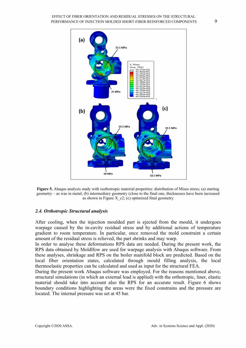
2.4. Orthotropic Structural analysis
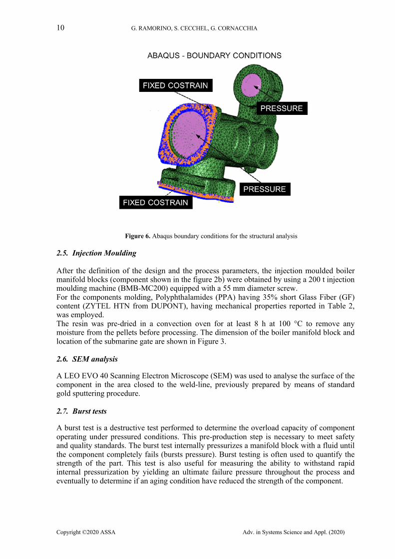
After cooling, when the injection moulded part is ejected from the mould, it undergoes warpage caused by the in-cavity residual stress and by additional actions of temperature gradient to room temperature. In particular, once removed the mold constraint a certain amount of the residual stress is relieved, the part shrinks and may warp. In order to analyse these deformations RPS data are needed. During the present work, the RPS data obtained by Moldlfow are used for warpage analysis with Abaqus software. From these analyses, shrinkage and RPS on the boiler manifold block are predicted. Based on the local fiber orientation states, calculated through mould filling analysis, the local thermoelastic properties can be calculated and used as input for the structural FEA. During the present work Abaqus software was employed. For the reasons mentioned above, structural simulations (in which an external load is applied) with the orthotropic, liner, elastic material should take into account also the RPS for an accurate result. Figure 6 shows boundary conditions highlighting the areas were the fixed constrains and the pressure are located. The internal pressure was set at 45 bar.
10 G. RAMORINO, S. CECCHEL, G. CORNACCHIA
Copyright ©2020 ASSA Adv. in Systems Science and Appl. (2020)
Figure 6. Abaqus boundary conditions for the structural analysis
2.5. Injection Moulding After the definition of the design and the process parameters, the injection moulded boiler manifold blocks (component shown in the figure 2b) were obtained by using a 200 t injection moulding machine (BMB-MC200) equipped with a 55 mm diameter screw. For the components molding, Polyphthalamides (PPA) having 35% short Glass Fiber (GF) content (ZYTEL HTN from DUPONT), having mechanical properties reported in Table 2, was employed. The resin was pre-dried in a convection oven for at least 8 h at 100 °C to remove any moisture from the pellets before processing. The dimension of the boiler manifold block and location of the submarine gate are shown in Figure 3.
2.6. SEM analysis
A LEO EVO 40 Scanning Electron Microscope (SEM) was used to analyse the surface of the component in the area closed to the weld-line, previously prepared by means of standard gold sputtering procedure.
2.7. Burst tests
A burst test is a destructive test performed to determine the overload capacity of component operating under pressured conditions. This pre-production step is necessary to meet safety and quality standards. The burst test internally pressurizes a manifold block with a fluid until the component completely fails (bursts pressure). Burst testing is often used to quantify the strength of the part. This test is also useful for measuring the ability to withstand rapid internal pressurization by yielding an ultimate failure pressure throughout the process and eventually to determine if an aging condition have reduced the strength of the component.
EFFECT OF FIBER ORIENTATION AND RESIDUAL STRESSES ON THE STRUCTURAL PERFORMANCE OF INJECTION MOLDED SHORT-FIBER-REINFORCED COMPONENTS 11
Copyright ©2020 ASSA. Adv. in Systems Science and Appl. (2020)
3. RESULTS AND DISCUSSION 3.1. Mould filling analysis
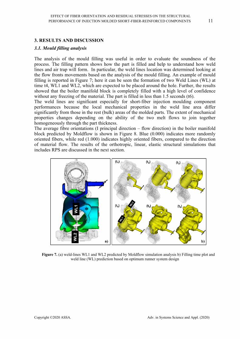
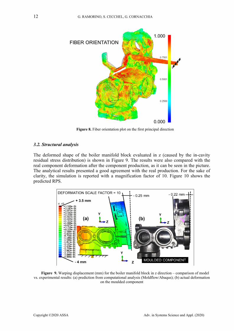
The analysis of the mould filling was useful in order to evaluate the soundness of the process. The filling pattern shows how the part is filled and help to understand how weld lines and air trap will form. In particular, the weld lines location was determined looking at the flow fronts movements based on the analysis of the mould filling. An example of mould filling is reported in Figure 7; here it can be seen the formation of two Weld Lines (WL) at time t4, WL1 and WL2, which are expected to be placed around the hole. Further, the results showed that the boiler manifold block is completely filled with a high level of confidence without any freezing of the material. The part is filled in less than 1.5 seconds (t6). The weld lines are significant especially for short-fiber injection moulding component performances because the local mechanical properties in the weld line area differ significantly from those in the rest (bulk) areas of the molded parts. The extent of mechanical properties changes depending on the ability of the two melt flows to join together homogeneously through the part thickness. The average fibre orientations (I principal direction – flow direction) in the boiler manifold block predicted by Moldflow is shown in Figure 8. Blue (0.000) indicates more randomly oriented fibers, while red (1.000) indicates highly oriented fibers, compared to the direction of material flow. The results of the orthotropic, linear, elastic structural simulations that includes RPS are discussed in the next section.
Figure 7. (a) weld-lines WL1 and WL2 predicted by Moldflow simulation analysis b) Filling time plot and weld line (WL) prediction based on optimum runner system design
12 G. RAMORINO, S. CECCHEL, G. CORNACCHIA
Copyright ©2020 ASSA Adv. in Systems Science and Appl. (2020)
Figure 8. Fiber orientation plot on the first principal direction
3.2. Structural analysis
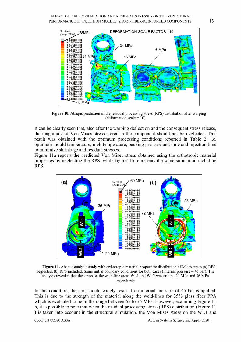
The deformed shape of the boiler manifold block evaluated in z (caused by the in-cavity residual stress distribution) is shown in Figure 9. The results were also compared with the real component deformation after the component production, as it can be seen in the picture. The analytical results presented a good agreement with the real production. For the sake of clarity, the simulation is reported with a magnification factor of 10. Figure 10 shows the predicted RPS.
Figure 9. Warping displacement (mm) for the boiler manifold block in z direction – comparison of model vs. experimental results: (a) prediction from computational analysis (Moldflow/Abaqus); (b) actual deformation
on the moulded component
EFFECT OF FIBER ORIENTATION AND RESIDUAL STRESSES ON THE STRUCTURAL PERFORMANCE OF INJECTION MOLDED SHORT-FIBER-REINFORCED COMPONENTS 13
Copyright ©2020 ASSA. Adv. in Systems Science and Appl. (2020)
Figure 10. Abaqus prediction of the residual processing stress (RPS) distribution after warping (deformation scale = 10)
It can be clearly seen that, also after the warping deflection and the consequent stress release, the magnitude of Von Mises stress stored in the component should not be neglected. This result was obtained with the optimum processing conditions reported in Table 2; i.e. optimum mould temperature, melt temperature, packing pressure and time and injection time to minimize shrinkage and residual stresses. Figure 11a reports the predicted Von Mises stress obtained using the orthotropic material properties by neglecting the RPS, while figure11b represents the same simulation including RPS.
Figure 11. Abaqus analysis study with orthotropic material properties: distribution of Mises stress (a) RPS neglected, (b) RPS included. Same initial boundary conditions for both cases (internal pressure = 45 bar). The
analysis revealed that the stress on the weld-line areas WL1 and WL2 was around 29 MPa and 36 MPa respectively
In this condition, the part should widely resist if an internal pressure of 45 bar is applied. This is due to the strength of the material along the weld-lines for 35% glass fiber PPA which is evaluated to be in the range between 65 to 75 MPa. However, examining Figure 11 b, it is possible to note that when the residual processing stress (RPS) distribution (Figure 11 ) is taken into account in the structural simulation, the Von Mises stress on the WL1 and
14 G. RAMORINO, S. CECCHEL, G. CORNACCHIA
Copyright ©2020 ASSA Adv. in Systems Science and Appl. (2020)
WL2 strongly increases to about 58 MPa and 72 MPa, respectively. These values are above the Von Mises strength of the weld-lines for this material, highlighting the relevance of this additional test.
3.3. SEM analysis
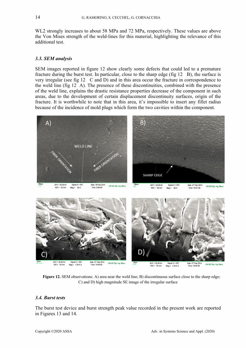
SEM images reported in figure 12 show clearly some defects that could led to a premature fracture during the burst test. In particular, close to the sharp edge (fig 12 B), the surface is very irregular (see fig 12 C and D) and in this area occur the fracture in correspondence to the weld line (fig 12 A). The presence of these discontinuities, combined with the presence of the weld line, explains the drastic resistance properties decrease of the component in such areas, due to the development of certain displacement discontinuity surfaces, origin of the fracture. It is worthwhile to note that in this area, it’s impossible to insert any fillet radius because of the incidence of mold plugs which form the two cavities within the component.
Figure 12. SEM observations: A) area near the weld line; B) discontinuous surface close to the sharp edge; C) and D) high magnitude SE image of the irregular surface
3.4. Burst tests
The burst test device and burst strength peak value recorded in the present work are reported in Figures 13 and 14.
EFFECT OF FIBER ORIENTATION AND RESIDUAL STRESSES ON THE STRUCTURAL PERFORMANCE OF INJECTION MOLDED SHORT-FIBER-REINFORCED COMPONENTS 15
Copyright ©2020 ASSA. Adv. in Systems Science and Appl. (2020)
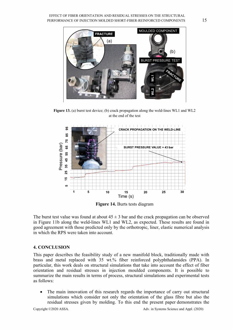
Figure 13. (a) burst test device; (b) crack propagation along the weld-lines WL1 and WL2 at the end of the test
Figure 14. Burts tests diagram
The burst test value was found at about 45 ± 3 bar and the crack propagation can be observed in Figure 11b along the weld-lines WL1 and WL2, as expected. These results are found in good agreement with those predicted only by the orthotropic, liner, elastic numerical analysis in which the RPS were taken into account.
4. CONCLUSION This paper describes the feasibility study of a new manifold block, traditionally made with brass and metal replaced with 35 wt.% fiber reinforced polyphthalamides (PPA). In particular, this work deals on structural simulations that take into account the effect of fiber orientation and residual stresses in injection moulded components. It is possible to summarize the main results in terms of process, structural simulations and experimental tests as follows:
• The main innovation of this research regards the importance of carry out structural simulations which consider not only the orientation of the glass fibre but also the residual stresses given by molding. To this end the present paper demonstrates the
16 G. RAMORINO, S. CECCHEL, G. CORNACCHIA
Copyright ©2020 ASSA Adv. in Systems Science and Appl. (2020)
usefulness and accuracy of an integrated CAD-FEA approach composed of coupled 3D flow and structural simulations applied at the optimization of injection moulding. In particular, the simulations are based on orthotropic, linear, elastic simulations that include the Residual Process Stress (RPS).
• The integration of RPS data leads to a much more reliable prediction of the actual product response that allows to obtain optimized part strength, part geometry, mold design and processing conditions. In the examined case, the Von Mises stress on the WL1 and WL2 strongly increases respectively from 29 MPa and 36 MPa, in simulations without RPS, up to about 58 MPa and 72 MPa, when the RPS distribution is taken into account. These values highlighted the relevance of this additional test.
• Experimental tests, such as burst test and SEM analysis, were conducted on real components. The results were in good agreement with those predicted by the orthotropic, linear and elastic numerical analysis which considered the RPS, confirming the effective benefits obtained with this design methodology.
• The substitution of brass with 35 wt.% glass fiber filled PPA led to a final weight of 190 g, with a weight reduction of about 60% in comparison with the 480 g of the traditional one. The cost analysis reported in figure 2 shows a saving of about 65% respect to the original component.
This integrated CAD-FEA approach related to experimental work would be applied also in future applications for the further improvement of weight reduction and metal replacement.
ACKNOWLEDGEMENTS The authors are grateful to Fonditalia SpA for the realization of workpieces.
REFERENCES
1. S. Cecchel, D. Chindamo, M. Collotta, G. Cornacchia, A. Panvini, G. Tomasoni, M. Gadola (2018). Lightweighting in light commercial vehicles: cradle-to-grave life cycle assessment of a safety relevant component, The International Journal of Life Cycle Assessment, 1-12.
2. S. Kulkarni, D.J. Edwards, E.A. Parn, C. Chapman, C.O. Aigbavboa, R. Cornish (2018). Evaluation of vehicle lightweighting to reduce greenhouse gas emissions with focus on magnesium substitution, Journal of Engineering, Design and Technology, 869-888. DOI 10.1108/JEDT-03-2018-0042.
3. S. Cecchel, D. Chindamo, E. Turrini, C. Carnevale, G. Cornacchia, M. Gadola, A. Panvini, M. Volta, D. Ferrario, R. Golimbioschi (2018). Impact of reduced mass of light commercial vehicles on fuel consumption, CO2 emissions, air quality, and socio-economic costs, Science of the Total Environment, 613(14), 409-417.
4. M. Tisza, I. Czinege (2018). Comparative study of the application of steels and aluminium in lightweight production of automotive parts, International Journal of Lightweight Materials and Manufacture, 1, 229-238.
5. M. Faccoli, D. Dioni, S. Cecchel, G. Cornacchia, A. Panvini (2017). An experimental study to optimize the heat treatment of gravity cast Sr-modified B356 aluminum alloy, Transactions of Nonferrous Metals Society of China, 27(8), 1698-1706.
EFFECT OF FIBER ORIENTATION AND RESIDUAL STRESSES ON THE STRUCTURAL PERFORMANCE OF INJECTION MOLDED SHORT-FIBER-REINFORCED COMPONENTS 17
Copyright ©2020 ASSA. Adv. in Systems Science and Appl. (2020)
6. E. Scharifi, R. Knoth, U. Weiding (2019). Thermo-mechanical forming procedure for high strength Aluminum sheet with improved mechanical properties and process efficiency, Procedia Manufactoring, 29, 481-489.
7. K. Zheng, D. J. Politis, L. Wang, J. Lin (2018). A review on forming techniques for manufacturing lightweight complex-shaped aluminum panel components, International Journal of Lightweight Materials and Manufacture, 1, 55-80.
8. S. Cecchel, G. Cornacchia, A. Panvini (2016). Cradle-to-Gate Impact Assessment of a High-Pressure Die-Casting Safety-Relevant Automotive Component, JOM: the journal of the Minerals, Metals & Materials Society, 68, 2443-2448.
9. J. M. Garcés, D. J. Moll, J. Bicerano, R. Fibiger, D. G. McLeod (2000). Polymeric Nanocomposites for Automotive Applications, Adv. Mater., 12(23), 1835-1839.
10. S. Donnini Mancini, A. de Oliveira Santos Neto, M. Odila Hilario Cioffi and E. C. Bianchi, (2017). Replacement of metallic parts for polymer composite materials in motorcycle oil pumps, Journal of Reinforced Plastics and Composites, 36(2), 149–160.
11. Vinny R. Sastri (2010). Plastics in medical devices: properties, requirements and applications, First Ed. Elsevier Inc.
12. Bhanshali, S., (2014). A Lightweighting Solution for Converting an Aluminum Bracket to Plastic Using Long Fiber Thermoplastic Technology, SAE Technical Paper, 2014-28-0010, 2014, doi:10.4271/2014-28-0010.
13. S. Cecchel, D. Ferrario, A. Panvini, G. Cornacchia (2018). Lightweight of a cross beam for commercial vehicles: development, testing and validation, Materials and Design, 149, 122–134.
14. A. Taub, E. De Moor, A. Luo, D. K. Matlock, J. G. Speer and U. Vaidy (2019). Materials for Automotive Lightweighting, Annu. Rev. Mater. Res., 49, 327–59, https://doi.org/10.1146/annurev-matsci-070218-010134.
15. Z. J. Gombos, P. McCutchion, L. Savage (2019). Thermo-mechanical behaviour of composite moulding compounds at elevated temperatures, Composites Part B, 173, 106921, 1-11.
16. G. Cornacchia, S. Cecchel, A. Panvini (2017). A comparative study of mechanical properties of metal inert gas (MIG)-cold metal transfer (CMT) and fiber laser-MIG hybrid welds for 6005A T6 extruded sheet, The International Journal of Advanced Manufacturing Technology, 94(5–8), 2017–2030.
17. Rosato D. V., Rosato D. V., Rosato M. V. (2004). Plastic Product Material and Process Selection Handbook, Elsevier Science.
18. Mortazavian, S., Fatemi, A. (2015). Effects of mean stress and stress concentration on fatigue behavior of short fiber reinforced polymer composites, Fatigue & Fracture Of Engineering Materials & Structures, 39(2), 149-166.
19. Mortazavian, S., Fatemi, A. (2015). Effects of fiber orientation and anisotropy on tensile strength and elastic modulus of short fiber reinforced polymer composites, Composites Part B-Engineering, 72, 116-129.
20. Schaaf, A., De Monte, M., Moosbrugger, E., Vormwald, M., Quaresimin, M. (2015). Life estimation methodology for short fiber reinforced polymers under thermo-mechanical loading in automotive applications, Materialwissenschaft Und Werkstofftechnik, 46(2), 214-228.
21. Hartl, A. M., Jerabek, M., Freudenthaler, P., Lang R.W. (2015). Orientation-dependent compression/tension asymmetry of short glass fiber reinforced polypropylene: Deformation, damage and failure, Composites Part A-Applied Science And Manufacturing, 79, 14-22.
22. Launay, A., Marco, Y., Maitournam, M. H., Raoult I., Szmytka F. (2010). Cyclic behavior of short glass fiber reinforced polyamide for fatigue life prediction of automotive components. 10th International Fatigue Conference, Prague, Czech Republic, Jun 06-11, 2010, Fatigue 2010, Book Series: Procedia Engineering, 2(1), 901-910.
18 G. RAMORINO, S. CECCHEL, G. CORNACCHIA
Copyright ©2020 ASSA Adv. in Systems Science and Appl. (2020)
23. C. Kahl, M. Feldmann, P. Sälzer, H.-P. Heim (2018). Advanced short fiber composites with hybrid reinforcement and selective fiber-matrix-adhesion based on polypropylene – Characterization of mechanical properties and fiber orientation using high-resolution X-ray tomography, Composites Part A, 111, 54–61.
24. X. Yan, S. Cao (2018). Structure and interfacial shear strength of polypropylene-glass fiber/carbon fiber hybrid composites fabricated by direct fiber feeding injection molding, Composite Structures, 185, 362–372.
25. R. M. Bajracharya, A. C. Manalo, W. Karunasena, K.T. Lau (2016). Experimental and theoretical studies on the properties of injection moulded glass fibre reinforced mixed plastics composites, Composites. Part A, 393-405.
26. Chung D., Kwon T. (2002). Fiber orientation in the processing of polymer composites. Korea-Aust Rheol J., 14, 175-188.
27. Ayadi A., Nouri H., Guessasma S, Roger F. (2015). An original approach to assess elastic properties of a short glass fibre reinforced thermoplastic combining X-ray tomography and finite element computation, Composite Structures, 125, 277-286.
28. J. Jansson, T. Gustafsson, K. Salomonsson, J. Olofsson, J. Johansson, P. Appelsved, M. Palm (2018). An anisotropic non-linear material model for glassfibre reinforced plastics, Composite Structures, 195, 93-98.
29. M. Zaidani, M. A. Omar, S. Kumar (2015). Coupling of injection molding process to mechanical properties of short fiber composites: A through process modeling approach, Journal of Reinforced Plastics and Composites, 34(23), 1963–1978.
30. Wu C.H., Liang W.J. (2005). Effects of Geometry and Injection-Molding Parameters on Weld-Line Strength, Polymer Engineering And Science, 1021-1030.
31. Liu S.-J., Wu J.-Y., Chang J.-H. & Hung S.-W. (2000). An Experimental Matrix Design to Optimize the Weldline Strength in Injection Molded Parts, Polym. Eng. Sci., 40(5), 1256 -1262.
32. Fellahi S., Meddad A.,Fisa B., Davis B.D. (1995). Weldlines in injection‐molded parts: A review, Adv. Polym. Technol., 14(3), 169-195.
33. M. B. Baradi, C. Cruz, T. Riedel, G. Régnier, (2019). Mechanical and microstructural characterization of flowing weld lines in injection-molded short fiber-reinforced PBT, Polymer Testing, 74, 152–162.
34. Ayadi A., Nouri H., Guessasma S., Roger F. (2016). Large-Scale X-Ray Microtomography Analysis of Fiber Orientation in Weld Line of Short Glass Fiber Reinforced Thermoplastic and Related Elasticity Behavior, Macromolecular Materials And Engineering, 301(8), 907-921.
35. Fiebig I., Schoeppner V. (2016). Influence of the Initial Fiber Orientation on the Weld Strength in Welding of Glass Fiber Reinforced Thermoplastics, International Journal Of Polymer Science, Article ID: 7651345, 1-16.
36. Kagitci Y.C., Tarakcioglu N. (2016). The effect of weld line on tensile strength in a polymer composite part, International Journal Of Advanced Manufacturing Technology, 85(5-8), 1125-1135.
37. Woo, J.W., Hong J.S., Kim H.K. (2016). Analysis of Residual Stress and Birefringence in a Transparent Injection Molded Article for Molding Condition. Polymer-Korea, 40(2), 175-180.
38. Jansen K. M. B. Edited (2015). Residual Stresses In Injection Molded Products. GT70 International Conference, Salerno, Italy, Oct 15-17, 2015. Book Series: AIP Conference Proceedings, 1695, Article Number: 020007.
39. Liu W., Wang X., Li Z. (2016). Integration optimization of molding and service for injection-molded product, International Journal Of Advanced Manufacturing Technology, 84 (9-12), 2019-2028.
40. Foss P.H. (2004). Coupling of Flow Simulation and Structural Analysis for Glass-Filled Thermoplastics, Polymer Composites, 25(4), 343-354.
EFFECT OF FIBER ORIENTATION AND RESIDUAL STRESSES ON THE STRUCTURAL PERFORMANCE OF INJECTION MOLDED SHORT-FIBER-REINFORCED COMPONENTS 19
Copyright ©2020 ASSA. Adv. in Systems Science and Appl. (2020)
41. Wang J., Cook P., Bakharev A., Costa F., Astury D. (2016). Prediction of fiber orientation in injection-molded parts using three-dimensional simulations, AIP Conference Proceedings, 1713, 040007, https://doi.org/10.1063/1.4942272.
42. Foss P. H., Tseng H., Snawerdt J., Chang Y., Yang W., and Hsu C. (2014). Prediction of fiber orientation distribution in injection molded parts using Moldex3D simulation, Polymer Composites, 35(4), 671–680.
43. Kulkarni A., Aswini N., Dandekar C. R. (2012). Modeling of short fiber reinforced injection moulded composite. International Conference on Structural Nano Composites (NANOSTRUC) 2, Book Series: IOP Conference Series-Materials Science and Engineering, 40, Article Number: 012025.
44. Folgar F., Tucker C. (1984). Orientation behavior of fibers in concentrated suspensions. J Reinf Plast Comp., 3, 98–119.
45. Whiteside B.R., Coates P.D., Hine P.J., Duckett R.A. (2000). Glass fibre orientation within injection moulded automotive pedal. Simulation and experimental studies, Plast. Rubber Compos., 29(1) 38-45.
46. Moyak D.M. (1996). The effect of injection molding and material parameters on molded and annealed polyphthalamide. Soc Plast Engineers Inc, 54th Annual Technical Conference of the Society-of-Plastics-Engineer – Plastics: Racing into the Future (ANTEC 96), 1996, Indianapolis.
47. Pechulis M., Vautour D. (1998). The effect of thickness on the tensile and impact properties of reinforced thermoplastics, Journal Of Reinforced Plastics And Composites, 17(17), 1580-1586.
48. Tandon G. P., Weng G. J. (1984). The effect of aspect ratio of inclusions on the elastic properties of unidirectionally aligned composites, Polym. Comp., 5, 327.