Embed Size (px)
Citation preview

Effect of filter–separators on the clogging ofleachate collection systems
Reagan McIsaac and R. Kerry Rowe
Abstract: This paper reports the results obtained after 6 years operation of nine mesocosm experiments that simulatethe 50 cm of the drainage layer closest to the leachate collection pipe in a landfill. Five different design configurationswere examined involving a 300 mm thick layer of coarse (38 mm) gravel. The designs differed in terms of the pres-ence, nature, and location of a filter–separator layer either at the waste–gravel interface or partway through the gravel.A nonwoven geotextile filter–separator (GTF/S) is shown to reduce clogging of the gravel relative to the no filter–separator or woven GTF/S designs. Some clogging of the geotextiles is reported, with reductions in geotextile hydraulicconductivity of 23% for the woven GTF/S, 74%–89% for the nonwoven GTF/S, and 75%–94% for the nonwovengeotextile partway through the gravel. The clogged nonwoven geotextile filter–separator maintained a higher hydraulicconductivity than the extracted woven geotextile. Of the designs with a filter–separator between the waste and gravel,the granular filter–separator most effectively reduced clogging of the gravel but at the expense of leachate moundingabove the sand once the sand layer clogs. The design with a nonwoven geotextile partway through the gravel (GTMF)provides better protection of the underlying gravel from clogging than other designs involving a geotextile.
Key words: landfill, waste, leachate, clogging, biofilm, geotextile.
Résumé : On présente les résultats obtenus après six années d’opération de neuf expériences de mésocosmes qui sti-mulent les 50 cm de la couche de drainage la plus près du tuyau de collecte du lixiviant dans un enfouissement sani-taire. On a examiné cinq différentes configurations de conception impliquant 300 mm d’épaisseur de gros (38 mm)gravier. Les conceptions étaient différentes en termes de la présence, de la nature et de la localisation de la couchefiltre–séparateur soit à l’interface résidus–gravier, soit à mi-chemin à travers le gravier. On a montré qu’un filtre–séparateurde géotextile non tissé (GTF/S) réduit le colmatage du gravier par rapport aux conceptions sans filtre–séparateur ouGTF/S tissé. On rapporte qu’il y a du colmatage du géotextile avec les réductions de la conductivité hydraulique dugéotextile variant de 23 % pour le GTF/S tissé, de 74 % à 89 % pour le GTF/S non tissé, et de 75 % à 94 % pour legéotextile non tissé à mi-chemin à travers le gravier. Le filtre–séparateur en géotextile non tissé colmaté a maintenu uneconductivité hydraulique plus élevée que le géotextile tissé extrait. Parmi les conceptions comportant un filtre–séparateurentre les résidus et le gravier, le filtre–séparateur granulaire a réduit le colmatage du gravier de la façon la plus effi-cace, mais aux dépends de la formation de buttes au-dessus du sable lorsque la couche de sable se colmate. La concep-tion avec un géotextile non tissé à mi-chemin dans le gravier (GTMF) fournit une meilleure protection contre lecolmatage du gravier sous-jacent que les autres conceptions impliquant un géotextile.
Mots clés : enfouissement sanitaire, résidus, lixiviant, colmatage, biofilm, géotextile.
[Traduit par la Rédaction] McIsaac and Rowe 693
Introduction
Modern landfills typically have a leachate collection sys-tem (LCS) to control leachate mounding on the liner and tocollect and remove contaminants that would otherwise beavailable for transport to the environment. Typically, theLCS comprises a layer (“blanket”) of granular material and a
network of perforated leachate collection pipes. Field experi-ence (Brune et al. 1994; Fleming et al. 1999; Maliva et al.2000; Bouchez et al. 2003) has shown, however, that thegrowth of biofilms on the material in the collection layer in-duces the deposition of inorganic constituents (predomi-nantly calcium carbonate) from the leachate and theaccumulation of particulate matter; this process is referred toherein as clogging. A leachate collection system is said to beclogged when its hydraulic conductivity drops to the pointwhere the leachate head on the liner exceeds the designvalue (typically 0.3 m; Rowe et al. 2004). This buildup ofclog material can occur in the granular drainage layer, ingeotextiles, and in the leachate collection pipe perforationsor the pipes themselves. The clog that develops decreasesthe pore space available to transmit leachate, reducing thehydraulic conductivity and consequently the efficiency ofthe leachate collection system. The physical blocking of thegranular drainage layer due to intrusion of waste material
Can. Geotech. J. 43: 674–693 (2006) doi:10.1139/T06-030 © 2006 NRC Canada
674
Received 25 June 2005. Accepted 10 March 2006. Publishedon the NRC Research Press Web site at http://cgj.nrc.ca on16 June 2006.
R. McIsaac. Department of Civil and EnvironmentalEngineering, University of Western Ontario, London,ON N6A 5B9, Canada.R.K. Rowe.1 Department of Civil Engineering,GeoEngineering Centre at Queen’s – RMC, Queen’sUniversity, Kingston, ON K7L 3N6, Canada.
1Corresponding author (e-mail: [email protected]).

from above is also important. Since leachate collection sys-tems may be required to collect and remove leachate for ex-tended periods of time, it is important to be able to designthese systems to minimize the clogging process and prolongthe service life of these systems.
The work of Brune et al. (1994) and Rowe et al. (2000a)has clearly shown that the particle size of the granular mate-rial in the drainage layer is important, with smaller grainsize material resulting in faster clogging. These findingsdemonstrate the desirability of using coarse, uniform gravel.This said, although there are many different opinions regard-ing what is the most suitable design (as manifest by themany different LCS design configurations used in practice),there is a paucity of data regarding the relative performanceof different systems and their susceptibility to clogging. Forexample, there have been conflicting opinions expressed re-garding the suitability of placing a geotextile or granular fil-ter between the waste and underlying granular material.Likewise, there are different opinions regarding whether thegeotextile should be placed directly between the waste andgravel or at some location within the gravel layer. Some re-searchers have opined that because geotextiles experience areduction in hydraulic conductivity due to clogging, theyshould not be used in landfill leachate collection systems.While acknowledging clogging, Rowe (1993, 1998) has in-dicated that a filter between the waste and underlying granu-lar material may be beneficial if used correctly. In support ofthe latter opinion, Fleming et al. (1999) reported observa-tions from a field exhumation of a leachate collection systemwith a 50 mm gravel drainage blanket drain at a large mu-nicipal landfill site. After 4 years of exposure to municipallandfill leachate, the drainage gravel was found to contain aconsiderable mass and volume of clog materials. At one lo-cation where a sand fill and geotextile were placed betweenthe waste and the drainage gravel, the observed clogging ofthe underlying gravel was considerably less than at locationswhere there was no filter present. This suggests a potentialbeneficial effect of the geotextile in terms of acting as a sep-arator, minimizing intrusion of particulate material into thedrainage gravel and the potential for reducing clogging due
to leachate treatment that may occur as the leachate passesthrough the geotextile (or granular filter).
To investigate the effect of a number of different designconfigurations with and without the use of filter–separatorlayers, a series of experiments was initiated as described byFleming and Rowe (2004). These experiments were de-signed to examine in real time and at real scale the two-dimensional leachate flow conditions adjacent to a leachatecollection pipe in a primary leachate collection system in-volving a continuous granular drainage layer. Details regard-ing the design and early operation of these cells (calledmesocosms) are given by Fleming and Rowe. Relevant tothis paper are five different design configurations involving a300 mm thick layer of coarse gravel (38 mm). Design 1(denoted herein as “no F/S”) had no filter–separator layer.Three designs had a filter–separator between the waste mate-rial and gravel: the filter–separator was a nonwovengeotextile for design 2 (nonwoven GTF/S), a wovengeotextile for design 3 (woven GTF/S), and a graded granu-lar filter for design 4 (graded granular F/S). Design 5(nonwoven GTMF) had a nonwoven geotextile partwaythrough the gravel.
The primary objective of this paper is to examine the ef-fect of the different design configurations on the clogging ofthe gravel at the time of the termination of these tests after6 years operation. Particular attention is paid to the distribu-tion of clog material in the gravel (especially over the lastyear of operations). A secondary objective is to examine theclogging of the geotextiles used as filter–separators.
Methodology
Mesocosm fabrication and materialsThe mesocosm collection system cells (Fig. 1; Table 1)
were fabricated from welded 9 mm thick PVC sheeting andwere built at a large enough scale (internal dimensions mea-suring 565 mm in length, 235 mm in width, and 574 mm inheight) to simulate the last 0.5 m of a leachate collectionsystem adjacent to a leachate collection pipe at full scale andwith materials typically used in practice (Fleming and Rowe
© 2006 NRC Canada
McIsaac and Rowe 675
Fig. 1. Schematic of experimental mesocosm cells and the prescribed interval spacing and location over which wet mass measurementswere made within the mesocosms at termination (modified from Fleming and Rowe 2004).

2004). The collection system design generally consisted(Fig. 1) of waste material (a mix of refuse and cover soilwith a moisture content of 40%) overlying a 300 mm thickgravel drainage layer of crushed dolomitic limestone, over-lying a nonwoven geotextile–sand cushion graded at 1.5% toa half section of perforated PVC pipe (internal pipe diameterof 102 mm, two rows of perforations, perforation diameterof 15.9 mm, and perforation spacing along the pipe of 127 mm).
The crushed dolomitic limestone had a nominal size of38 mm (D10 = 20 mm, D60 = 27 mm, D85 = 33 mm).Mesocosm C-04 had waste directly over the gravel. Thefilter–separator layers between the waste material and drain-age gravel (Fig. 1) were (1) a nonwoven needle-punchedpolypropylene geotextile (Polyfelt TS650, Table 2) formesocosms C-01 and C-02, (2) a woven slit-film geotextile(Terratrack 24-15, Table 2) for mesocosms C-21 and C-22,and (3) a graded granular filter consisting of 40 mm each ofwell-graded concrete sand (D10 = 0.2 mm, D60 = 0.7 mm,D85 = 1.8 mm) and pea gravel (D10 = 5 mm, D60 = 8 mm,D85 = 10 mm) for mesocosms C-07 and C-08. For themesocosms (C-05 and C-06) with a geotextile in the gravellayer (16.3 cm below the waste), the same nonwovengeotextile was used as in case (1).
Mesocosm operationIn a typical modern leachate collection system, leachate
percolates vertically down through the waste and into thedrainage layer. The drainage layer then conveys the leachatehorizontally to collection pipes. The mesocosms weredesigned to mimic these flow conditions adjacent to a col-lection pipe. As described by Fleming (1999) and Fleming
and Rowe (2004), the mesocosms were permeated under an-aerobic conditions with leachate collected from the KeeleValley Landfill (Toronto, Ontario) at flow rates representa-tive of field conditions. The vertical infiltration rate wasspecified to correspond to an annual average percolation of0.2 m3·a–1·m–2 through the waste and was approximately73 mL/day. To simulate horizontal flow, leachate waspumped into the mesocosms at one end at a rate of2.4 mL/min (1.26 m3/a) and, after it flowed horizontallythrough the drainage gravel, entered the collection pipe andexited out the constant leachate level outflow at the down-stream end of the mesocosm. The horizontal flow rate wasselected to simulate the average horizontal flow in the drain-age layer near the collection pipe for a 25 m drainage path tothe pipe. Between collection and use, the leachate was keptstirred in a series of storage tanks in a room maintained at atemperature of 7 ± 2 °C before being delivered by gravity asrequired to a manifold for temperature equalization to that ofthe mesocosms (i.e., 27 ± 2 °C). The tests were conducted at27 ± 2 °C to simulate the conditions anticipated in an activeleachate collection system (Rowe et al. 2004). Variable-speed peristaltic pumps, each with dedicated pump channels,were used to deliver the leachate from the manifold to themesocosms. The bottom 100 mm of the drainage gravel ineach mesocosm remained saturated (this was the designleachate outflow elevation) and the top 200 mm unsaturatedduring operation.
Experimental analysisA testing program was implemented to monitor and quan-
tify the amount of clogging and changes in leachate compo-
© 2006 NRC Canada
676 Can. Geotech. J. Vol. 43, 2006
Polyfelt TS650 Terratrack 24-15 ASTM test method
Manufacturer Polyfelt Geosynthetics Terrafix Geosynthetics Inc. —Physical characteristic and polymer Continuous filament, nonwoven,
needle-punched polypropyleneWoven polypropylene —
Application Between waste and gravel; betweentwo gravel layers
Between waste and gravel —
Thickness at 2 kPa (mm) 2.3 0.5 D5199AOS (µm) 110 700 D4751Mass per unit area (g/m2) 235 140 D5261Grab tensile strength (N) 755 750 D4632Permittivity (s–1) 1.60 0.04 D4491
Table 2. Properties and placement in the mesocosms of the Polyfelt TS650 and Terratrack 24-15 geotextiles.
Test duration
Mesocosm FilterAverage initialgravel porosity
Distance from wasteto top of filter (cm) Days Years
C-04 None 0.41 — 2207 6.05C-01 Nonwoven geotextile 0.43 0 2250 6.16C-02 Nonwoven geotextile 0.45 0 2182 5.98C-21 Woven geotextile 0.41 0 2168 5.94C-22 Woven geotextile 0.42 0 2243 6.15C-07 Granular filter; 4 cm each of pea gravel and sand 0.46 0 2231 6.11C-08 Granular filter; 4 cm each of pea gravel and sand 0.44 0 1534 4.20C-05 Nonwoven geotextile between two gravel layers 0.39 16.3 2245 6.15C-06 Nonwoven geotextile between two gravel layers 0.48 16.3 2196 6.02
Table 1. Summary of mesocosm design variables.

sition both temporally and spatially. Water-quality testingwas performed on leachate samples collected from beforethe influent valve and after the effluent valve (McIsaac2006). These samples were tested immediately to measurechemical oxygen demand (COD), calcium (Ca2+) concentra-tion, and pH. Tests were performed to follow the change indrainable porosity (and hence the change in void volume)with time as clogging developed. The procedure adopted in-volved periodically saturating the entire drainage layer withleachate and then measuring the volume of the leachate re-moved from each prescribed interval. The measureddrainable porosity is the ratio of the volume of the leachateremoved to the total volume of the drained interval. Thedrainable porosity will be lower than the actual porosity be-cause of incomplete draining of the water under gravity dueto fluid adhering to the drainage medium and clog material.
Termination of nine mesocosms allowed for visual inspec-tion of the degree of clogging that occurred over a 6 year op-erational lifespan. The clogged drainage gravel was removedand stripped of clog material and mass measurements wereused to obtain the amount of wet solids within different in-tervals (Fig. 1) in the mesocosms. Clog material wasstripped from the gravel by first placing the gravel in a se-quence of sieves and sieving for 15 min, with the remainingclog material from each stone removed by hand with a ham-mer and large knife.
Wet solids is a measure of the mass of total wet clog ma-terial per sample section measured immediately after collec-tion from the mesocosm. It represents the combined massfrom biomass, chemical precipitates, and transported fines.The bulk density of the clog material was measured using amodified American Society for Testing and Materials(ASTM) method D854 (ASTM 1998).
Based on the mass of clog removed from the disassem-bled mesocosms, the bulk density of the clog material, andthe initial void volume in each sample section, the volume ofclog within each section and the resulting void volume occu-pancy (VVO) were calculated, where VVO is the ratio of thevolume of pore space occupied by clog material to the initialvoid volume. Thus a VVO of 100% would indicate that theinitial void volume is completely filled with clog material.
Clog samples were sent for elemental analysis to ascertainthe composition of the clog material. Hydraulic conductivitytesting (ASTM 1992) was conducted on both clean and ex-tracted clogged samples of the geotextile (both woven andnonwoven). The exhumed geotextiles were inspected forclog development using a scanning electron microscopecombined with energy dispersive X-ray analysis (SEM–EDX) (Hitachi S-4500 field emission SEM combined with aPhoenix EDAM III EDAX system). EDX analysis provides aquantitative method for detecting elements above atomicnumber five, with a minimum detection limit of approxi-mately 0.5 wt.%, for most elements. An accelerating voltageof 10 kV was used, which has a probing depth of approxi-mately 1.5 µm in a carbon-based substrate.
Leachate characteristics
The leachate used in the mesocosms was collected fromthe Keele Valley Landfill (KVL) located near Toronto, On-tario, Canada. This is a 99 ha landfill with a design capacity
of approximately 33 000 000 m3 that received municipalsolid waste from 1984 to 2002. The underdrain system is amix of french drains in the older stages and a full leachateunderdrain system in the newer sections. The leachate wascollected from a manhole on the main header line at thedownstream end of the leachate collection system. Theleachate generated at the KVL has been monitored regularlysince landfilling began. The analytical composition of the“raw” KVL leachate used in the mesocosms during their op-eration is reported in Table 3.
It is generally accepted that waste progresses through fourstages of decomposition: aerobic, anaerobic acid, initialmethanogenic, and stable methanogenic (Christensen andKjeldsen 1995). The general trends with respect to ranges ofconcentrations and time dependency of selected parametersof KVL leachate coincide with the numerous landfills stud-ied in Germany by Ehrig (1983), in the US (Wisconsin) byKrug and Ham (1997), and in Denmark by Kjeldsen andChristophersen (2001).
During the operation of the mesocosms (1993–1999) theleachate had a high organic strength (dissolved organic car-bon (DOC), biochemical oxygen demand (BOD5), and CODvalues) indicative of a young leachate. The organic strengthwas mainly in the form of volatile fatty acids (McIsaac2006). The BOD to COD ratio and pH from 1993 to 1999indicate that the Keele Valley leachate was initially aceto-genic with a gradual transition into the initial methanogenicstage after 1996. A drop in the organic strength of the leach-ate in 1994 and 1995 with a subsequent increase in 1996was attributed to the placement of fresh waste over old inconjunction with lower total precipitation between 1992 and1994 (Armstrong and Rowe 1999).
Both the influent and effluent leachate were monitoredwith time but they are not discussed herein because the fo-cus of this paper is on the effect of the filters–separators onthe clogging of the gravel. The interested reader is referredto McIsaac (2006).
Drainable porosity results
The initial drainable porosities in the mesocosms rangedbetween 0.39 and 0.48. Drainable porosity measurementsmade within the mesocosms for the first 1500 days were re-ported by Fleming and Rowe (2004). Figures 2 and 3 showthe variation in the average drainable porosity in the unsatu-rated and saturated zones from inception to termination. Inthe present paper, particular attention is focused on the dif-ference in clogging with position in the gravel. Figure 4 il-lustrates pictorially a vertical profile through each mesocosmshowing the material filling each mesocosm and the intervalspacing and location over which the drainable porosities weremeasured within the mesocosms. Narrow intervals were usedin the saturated gravel layer and in the unsaturated gravel di-rectly above and below the design leachate outflow level.The measured interval height and locations were selected tomonitor the clog development directly above and below thenonwoven GTMF in the gravel layer. The variation indrainable porosity measured within each interval within themesocosms and its change with time between 1600 days andtest termination (2168–2252 days) are shown in Figs. 5 and 6.
© 2006 NRC Canada
McIsaac and Rowe 677

Clogging tended to decrease as one moved up from the bot-tom of the gravel, with the greatest clogging being in the ini-tially saturated zone (Figs. 5, 6). Once the upper portion ofthe saturated gravel (–2 to 0 cm) reached a drainable porosityof approximately 0.25–0.20, the drainable porosity in the in-terval above it (0–2 cm) began to decrease. This may be asso-ciated with clogging of the lower gravel and the lowerperforations in the leachate collection pipe to the point wherethe leachate level rose to allow flow through the uppermostperforation in the pipe, causing saturation of the interval from0 to 2 cm. This resulted in a consequent increased rate ofclogging in this zone (attributed to the increased mass loadingas leachate preferentially flowed in this less clogged zone to-ward the upper perforations). The clog within the pipes wassoft black runny biological ooze (Fig. 7). A hard clog depositonly existed as a thin layer on the inside surface of the pipesthat was constantly submerged–saturated. These results showthe importance of keeping the leachate level low (minimizingthe thickness of the saturated zone) and the desirability ofkeeping the pipe and pipe perforations from clogging by regu-lar cleaning of the pipes.
The much greater rate of clog development within the sat-urated gravel layers compared with the unsaturated gravel
(Figs. 5, 6) is attributed to the higher mass loading in thesaturated zone due to the higher flow rate. This is consistentwith the findings of Rowe et al. (2000b). One can also iden-tify a difference in the rate of clogging in the unsaturatedzone in the different mesocosms, however, and this can beassociated with the different filter–separator designs. Highdrainable porosities (typically greater than 0.40) were mea-sured within the unsaturated gravel layer adjacent to thewaste in the mesocosms that incorporated a separator be-tween the waste and the gravel, for example in the 14–18 cminterval within the design incorporating the nonwovengeotextile (Figs. 5b, 5c), the woven geotextile (Figs. 5d, 5e),and the granular filter (Fig. 6a). Reduced drainable porositymeasurements (typically around 0.35) were obtained in thesame interval in designs without a separator (i.e., Figs. 5a,6b, and 6c). Thus the filter–separator between the waste andthe gravel reduced waste intrusion into the gravel.
Clogging of the saturated zone was also influenced by thedesign. The mesocosms with the woven GTF/S (Figs. 5d,5e) had generally lower drainable porosities in the saturatedzone than those with a nonwoven GTF/S (Figs. 5b, 5c). Infact, mesocosm C-21 designed with a woven GTF/S exhib-ited the lowest drainable porosities of all mesocosms with a
© 2006 NRC Canada
678 Can. Geotech. J. Vol. 43, 2006
Yeara
Parameter1993(10)
1994(11)
1995(12)
1996(13)
1997(14)
1998(15)
1999(16)
pH 6.5 7.4 7.1 7.0 7.1 7.3 7.4DOC 5 470 2 140 1 760 5 510 4 510 3 750 3 630BOD5 12 210 3 910 3 510 11 350 8 110 6 810 5 130
COD 16 150 5 990 5 050 17 060 13 370 11 380 9 520BOD5/COD 0.75 0.95 0.71 0.81 0.60 0.59 0.53
Conductivity 16 350 14 780 10 120 18 450 17 830 17 610 19 700Calcium 1 250 430 470 1 190 630 610 470Sulphate 1 9 16 227 153 164 93Iron 185 18 50 222 225 192 122Manganese 10 410 970 3 630 9 460 6 680 4 590 3 180Chloride 2 230 2 420 1 380 2 380 3 050 2 960 3 020Ammonia-N 500 540 400 880 970 1 010 1 130Potassium 760 720 430 760 930 1 000 970Sodium 1 500 1 660 910 1 680 2 010 2 100 2 200Zinc 1.11 0.35 0.71 2.77 7.91 7.36 8.35Cadmium 0.027 0.004 0.007 0.010 0.026 0.026 0.003Chromium 0.239 0.061 0.118 0.237 0.166 0.140 0.159Lead 0.027 0.016 0.013 0.008 0.011 0.022 0.026Mercury 0.0003 0.0096 0.0003 0.0001 0.0001 0.0001 0.0002Magnesium 450 420 210 410 430 470 450TKN 600 620 440 980 1 110 1 100 1 240Arsenic 0.041 0.007 0.004 0.002 0.031 0.030 0.058Cobalt 0.039 0.000 0.009 0.051 0.051 0.056 0.075Copper 0.023 0.009 0.035 0.015 0.014 0.021 0.020Nickel 0.308 0.149 0.216 0.806 0.685 0.576 3.322Barium 0.442 0.142 0.195 0.273 0.296 0.278 0.267Selenium 0.390 0.003 0.002 0.006 0.030 0.006 0.016Silver 0.017 0.011 0.005 0.007 0.006 0.000Aluminum 1.20 0.33 0.55 0.85 1.03 1.49 1.81
Note: All parameters are in mg/L, except pH. TKN, total Kjeldahl nitrogen.aNumber of years of operation is given in parentheses.
Table 3. Characteristics of landfill leachate collected from the Keele Valley Landfill during the operation of the mesocosms.

filter–separator, with values of less than 0.21 (even withinthe 0–2 cm interval) by 1625 days (4.6 years). Decreaseddrainable porosity values were measured in the 2–6 cm in-terval as early as 1750 days. Although not as severe as C-21,its duplicate C-22 had drainable porosities that were gener-ally less than 0.22 in the saturated gravel after 1625 days.The design with the graded granular filter (Fig. 6a) had thelowest clogging of the saturated zone, and the drainable po-rosity never dropped below 0.20. Disassembly results (dis-cussed later in the paper) indicate that the granular filtermay be the most effective at reducing the leachate massloading to the gravel and the amount of fines entering the
gravel layer as the leachate percolates vertically through thesystem, resulting in the higher observed drainable porositywithin the gravel drainage layer.
For the designs with a nonwoven GTMF (Figs. 6b, 6c) inthe gravel, the measured drainable porosities indicate thatthe geotextile was a site for clog development. Lowerdrainable porosities were measured within the interval thatcontained the geotextile and decreased with time, indicatingthat the geotextile was clogging. This can be seen in Figs. 6band 6c for the 2–6 cm interval, which contained the geo-textile. The interval directly above the geotextile (6–10 cm)had lower drainable porosities than the overlying unsaturated
© 2006 NRC Canada
McIsaac and Rowe 679
Fig. 2. Variation in drainable porosity with time: (a) no F/S, C-04; (b) nonwoven GTF/S, C-01; (c) nonwoven GTF/S, C-02; (d) wovenGTF/S, C-21; (e) woven GTF/S, C-22 (data up to 1400 days from Fleming and Rowe 2004).

gravel, consistent with observations of higher amounts ofclog above the geotextile than elsewhere in the unsaturatedzone. The drainable porosities above the geotextile were stillsignificantly greater than that measured in the saturated
gravel, however, and would likely still provide an alternatemeans for leachate flow should the geotextile clog suffi-ciently to prevent the free flow of leachate through it withleachate perching.
© 2006 NRC Canada
680 Can. Geotech. J. Vol. 43, 2006
Fig. 3. Variation in drainable porosity with time: (a) graded granular F/S, C-07; (b) graded granular F/S, C-08; (c) nonwoven GTMF,C-05; (d) nonwoven GTMF, C-06 (data up to 1400 days from Fleming and Rowe 2004).
Fig. 4. Vertical profiles through the mesocosms showing the interval spacing and location over which drainable porosities were mea-sured within the mesocosms: (a) no F/S (C-04), nonwoven GTF/S (C-01, C-02), woven GTF/S (C-21, C-22); (b) graded granular F/S(C-07); (c) nonwoven GTMF (C-05, C-06).

Disassembly results
No filter–separator design findingsWithout a separator between the waste and the gravel
drainage layer, the waste material physically intruded (due tocompaction and settlement of the waste) into the relativelylarge open voids to a depth of up to 60 mm, partially fillingthe voids (Fig. 8a) and reducing the effective thickness ofthe drainage layer. Approximately eight times more wet sol-ids (Fig. 9) were measured within this interval (260–300 mm) than in mesocosms designed with a separator. The
filter–separator between the waste and the gravel drainagelayer in the other mesocosms prevented this physical intru-sion of waste material and the subsequent reduction in voidvolume within the top 60 mm of the gravel drainage layer.
The absence of a filter–separator resulted in more clogmass throughout the drainage layer, higher VVO values(Table 4), and more severe cementation of the gravel withinthe saturated layer than was observed for designs incorporat-ing a filter–separator between the waste and the gravel drain-age layer. There was a distinct difference in the visualquantity of clog (Figs. 8d, 8e), and generally more clog mass
© 2006 NRC Canada
McIsaac and Rowe 681
Fig. 5. Drainable porosities in the mesocosms designed with (a) no F/S (C-04), (b) nonwoven GTF/S (C-01), (c) nonwoven GTF/S(C-02), (d) woven GTF/S (C-21), and (e) woven GTF/S (C-22).

(Fig. 9) was measured within all of the sample intervals inthe gravel for the designs without a filter–separator than forthose with a filter–separator between the waste material andthe drainage gravel. Of all the designs, the one with nofilter–separator had the highest VVO values within the satu-rated gravel layer (40% within the upper (50–100 mm) and76% within the lower (0–50 mm) saturated intervals)(Table 4). The use of a nonwoven GTF/S reduced the VVOwithin the upper and lower saturated gravel layers to 28%and 69%, respectively, and the use of the nonwoven GTMFin the gravel layer reduced the VVO to 35% and 56% withinthe upper and lower saturated gravel layers, respectively.For the designs without a waste–gravel separator, visiblymore fines accumulated on the top surfaces of the unsatu-rated gravel, and biofilm development was more abundant(i.e., more of the gravel surface was covered with biofilm),was thicker, felt grittier, and had more of a grey–tan colour(compared to black) than for the design with a filter–separator.A screwdriver was required to pry apart and remove all thegravel within the saturated gravel layer, indicating a higherdegree of cementation of the gravel particles to each otherwithin the saturated gravel layer in mesocosms without afilter–separator. In contrast, the gravel could be removed byhand when a filter was used.
Filter–separator designs
Woven geotextile filter–separator design (woven GTF/S)The design incorporating a woven GTF/S exhibited more
biological, physical, and chemical clogging, within both theunsaturated and saturated layers of the drainage gravel, thanwas observed for the nonwoven GTF/S designs, and theclogging approached what was observed when there was nofilter–separator (Fig. 9). Progressing down through the un-saturated gravel layer below the woven geotextile, theamount of biofilm increased and covered the flat top portionof the gravel where fluid and fines could accumulate. Thebiofilm that accumulated on the top of the gravel was lessthan 3 mm thick, soft, and viscous with a gritty feel, sug-gesting the accumulation of chemical precipitation and (or)particulates. The leachate flowing vertically through the wo-ven geotextile and unsaturated gravel was of sufficientstrength to support more biological growth on the unsatu-rated gravel than was the case with the nonwoven geotextileand granular filter designs. The degree of cementation (orthe force required to separate and remove the cementedgravel) within the saturated gravel layer was greater for thewoven GTF/S design than for the designs with a filter(nonwoven GTF/S, graded granular F/S, or nonwoven
© 2006 NRC Canada
682 Can. Geotech. J. Vol. 43, 2006
Fig. 6. Drainable porosities in the mesocosms designed with (a) graded granular F/S (C-07), (b) nonwoven GTMF (C-05), and(c) nonwoven GTMF (C-06).

GTMF). The soft clog was more dense, less slimy andrunny, and grittier than the soft clog in the saturated gravellayer of the nonwoven GTF/S design. Higher amounts of sil-icon and aluminum associated with the accumulation offines from the waste material were measured in the clog(Table 5) for the woven GTF/S design than for the designswith a nonwoven or granular filter.
Consistent with the foregoing observations of the filter–separator designs, the design incorporating the wovengeotextile had the greatest VVO throughout the drainagegravel at termination (Table 4). The differences in the clogtexture and composition (Table 5), the amount of clog(Table 4), and the degree of cementation within the saturatedgravel layer for the woven GTF/S compared with that forthose having other filter–separator designs suggest that themigration and accumulation of fines (originating from thewaste material) into the gravel and pipe and the lower degreeof leachate treatment within the woven geotextile (comparedwith the nonwoven geotextile and granular filter designs) in-fluenced the clog mechanism and as a result the drainagegravel below the woven geotextile design experienced in-creased clog compared to the nonwoven geotextile and gran-ular filter designs. Thus, while the woven GTF/S providedbetter performance than that without a filter–separator, thiswas the least desirable filter–separator design.
There was no appreciable biological, chemical, or physi-cal clogging of the woven geotextile, the waste materialabove it, or the underlying gravel in contact with thegeotextile. There was no biofilm visually evident where thewoven geotextile made direct contact with the underlyinggravel. Biofilm did grow in the capillary fringe of retainedleachate between the gravel and the woven geotextile. It ishypothesized that capillary action between the wovengeotextile and the gravel provided a moist environment formicrobial activity that caused the accumulation of biofilm to
occur at these locations. There was no cementation of thegeotextile to either the waste or gravel, however. When re-moved from the mesocosm, after 6 years, there was very lit-tle clog material on the woven geotextile. SEM images ofthe top and bottom surfaces (Fig. 10) of the extracted wovengeotextile show the presence of clog on its surface, but notan abundant accumulation. Only a very thin, relatively uni-form coating of clog material covered the surface of the wo-ven geotextile and caused a partial occlusion of the openingsbetween the fibres. EDX analysis of the material on the sur-face of the woven geotextile indicates the presence of siliconand aluminum due likely to fines (siltation) and calcium, ox-ygen, and carbon from chemical precipitate; however, therewas no evidence of a filter cake on the surface of the wovengeotextile that would have impeded the migration of finesfrom the waste material into the gravel. This is likely due tothe high apparent opening size (AOS = 700 µm) of the wo-ven GTF/S. There was no pooling of leachate on the surfaceof the woven geotextile, indicating that the permittivity wasstill sufficient to readily allow the flow of leachate throughthe geotextile. The extracted woven geotextile experiencedonly a 23% reduction in hydraulic conductivity from itsoriginal measured clean value of 2 × 10⁻⁵ m/s (Fig. 11). Theabsence of biological and chemical clogging above, directlybelow, or within the woven geotextile itself indicates thatthere was very little passive treatment of the leachate inthese areas and that, consequently, essentially all the inor-ganic and organic constituents in the leachate entered theunderlying gravel drainage layer with negligible attenuation.
Nonwoven geotextile filter–separator design (nonwovenGTF/S)
The nonwoven GTF/S reduced the amount of clog mate-rial in all sections of the underlying drainage layer (Fig. 9)by a factor of 1.2 (saturated gravel) to 2.4 (unsaturated
© 2006 NRC Canada
McIsaac and Rowe 683
Fig. 7. Soft black runny ooze that accumulated in the bottom of the half section of perforated pipe in the mesocosms. This, in con-junction with the high degree of clogging within the base saturated gravel layer, was sufficient to prevent the free flow of leachatethrough the bottom perforations of the pipe. The pipe was essentially pristine where unsaturated (i.e., see top section of the pipe abovethe perforations).
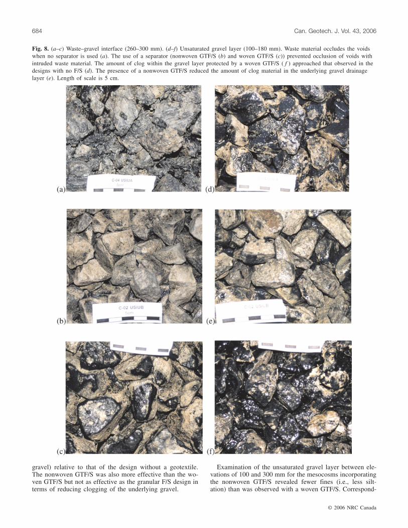
gravel) relative to that of the design without a geotextile.The nonwoven GTF/S was also more effective than the wo-ven GTF/S but not as effective as the granular F/S design interms of reducing clogging of the underlying gravel.
Examination of the unsaturated gravel layer between ele-vations of 100 and 300 mm for the mesocosms incorporatingthe nonwoven GTF/S revealed fewer fines (i.e., less silt-ation) than was observed with a woven GTF/S. Correspond-
© 2006 NRC Canada
684 Can. Geotech. J. Vol. 43, 2006
Fig. 8. (a–c) Waste–gravel interface (260–300 mm). (d–f) Unsaturated gravel layer (100–180 mm). Waste material occludes the voidswhen no separator is used (a). The use of a separator (nonwoven GTF/S (b) and woven GTF/S (c)) prevented occlusion of voids withintruded waste material. The amount of clog within the gravel layer protected by a woven GTF/S ( f ) approached that observed in thedesigns with no F/S (d). The presence of a nonwoven GTF/S reduced the amount of clog material in the underlying gravel drainagelayer (e). Length of scale is 5 cm.

ingly, the biofilm was less gritty and there was visibly lesssoft black biological film for the mesocosms with anonwoven GTF/S than for those with a woven GTF/S(Fig. 8).
Although the composition of the clog material collectedfrom the bottom saturated gravel interval (Table 5) indicatesonly a small difference in fines content from that of eitherthe nonwoven or woven geotextile designs, the silicon andaluminum contents in the clog material removed from thenonwoven GTF/S design were lower (Si = 1.22%/dry, Al =0.25%/dry) than those for the woven GTF/S design (Si =1.97%/dry, Al = 0.43%/dry), indicating that the nonwovengeotextile may have been slightly more effective as a filterthan the woven geotextile by reducing the amount of fines(clay particulates, siltation) mobilized and transported by thevertical flow of leachate to the gravel layer from the overly-ing waste material. SEM and EDX analysis (Fig. 12) of clogfrom the nonwoven GTF/S shows traces of Si and Al, indi-cating that fines (clay particles) originating from the wastematerial likely became embedded in the clog that developedin the nonwoven geotextile.
There was no evidence of a blinding layer on the top sur-face of the nonwoven GTF/S nor was there a uniform devel-opment of biofilm or a significant accumulation of finesthroughout the internal structure of the nonwoven geotextile.Clogging of the nonwoven GTF/S was observed, however,primarily due to the accumulation of precipitates. SEM pho-tographs of the clog within the nonwoven GTF/S are shownin Fig. 13. In general, clog that developed in the nonwovengeotextile did so by attachment to the geotextile fibres andseems to have propagated away from the intersection offibres. Clog development in the nonwoven GTF/S was rela-tively uniform and not exclusive to the gravel–geotextilecontacts; however, intense clog developed within thegeotextile at the locations where the gravel made contactwith the nonwoven geotextile (Fig. 14a) which cemented thegravel particles to the geotextile. The geotextile could beheld from one end, and the gravel would not fall off(Fig. 14b); substantial force was required to tear the gravelaway from the nonwoven geotextile. This is attributed to thefact that the gravel below the geotextile prevented verticalmovement of leachate through the geotextile at those loca-
© 2006 NRC Canada
McIsaac and Rowe 685
Interval(mm)
No F/S(C-04)
NonwovenGTF/S (C-01)
Woven GTF/S(C-22)
GGF/S(C-07)
NonwovenGTMF (C-05)
260–300 56 7 8 7 32180–260 9 7 9 7 8100–180 7 9 11 8 14
50–100 40 28 40 27 350–50 76 69 75 53 56
Note: F/S, filter–separator; GGF/S, graded granular filter–separator; GTF/S, geotextile filter–separator; GTMF,geotextile partway through the gravel.
Table 4. Void volume occupancy (VVO) within the mesocosms.
Fig. 9. Distribution of wet solids within the mesocosms.

tions, and hence any movement of leachate in the geotextilehad to be lateral to the edge of the gravel. This gave rise togreater retention of leachate on the top lateral surfaces of thegravel than in the adjacent geotextile where vertical flowcould occur, and consequently allowed the chemical reac-tions involved with biochemical precipitation to occur tocompletion. EDX analysis illustrates that the clog is mainlycomprised of calcium, carbon, and oxygen likely in the formof calcium carbonate. The SEM–EDX analysis of the clogdid indicate that the leachate was being treated, albeit at theexpense of some geotextile clogging.
The hydraulic conductivity results from the cleannonwoven geotextile and the partially clogged geotextile re-moved from the mesocosms indicate a 74%–89% reductionin hydraulic conductivity from its initial measured clean
value of 4.4 × 10⁻⁴ m/s (average of three samples; Fig. 11).The nonwoven geotextile experienced a greater loss in hy-draulic conductivity than the woven geotextile because itsstructure was more prone to clog formation. The hydraulicconductivity was still sufficiently high that ponding did notoccur on the geotextile even after 6 years exposure and afterdrainable porosities within the base of the gravel haddropped below 0.20. The nonwoven GTF/S was not a criti-cal location with respect to clog development (which was inthe underlying saturated zone). Although the nonwovengeotextile experienced greater clogging and thus greater re-ductions in hydraulic conductivity than the wovengeotextile, the measured hydraulic conductivities from theclogged samples of nonwoven geotextile from themesocosms after 6 years exposure to leachate were all
© 2006 NRC Canada
686 Can. Geotech. J. Vol. 43, 2006
Nonwoven GTMF (C-05)
Parameter
No F/S (C-04),lower saturatedgravel layer
Nonwoven GTF/S(C-01), lowersaturated gravellayer
Woven GTF/S(C-22), lowersaturated gravellayer
GGF/S (C-07),lower saturatedgravel layer
Lowersaturatedgravel layer
Geotextilesurface
Water content (%/wet) 74.5 66.9 61.1 72.2 65.6Organic matter (TVS; %/dry) 14.9 12.6 12.0 15.5 12.6Carbonate as CO3 (%/dry) 45.7 48.7 47.8 49.0 51.0 51.2Calcium, Ca (%/dry) 25.6 27.0 26.4 25.0 26.4 29.7Magnesium, Mg (%/dry) 2.24 2.52 2.70 4.06 3.91 2.20Silicon, Si (%/dry) 0.79 1.22 1.97 0.43 0.61 2.19Iron, Fe (%/dry) 5.10 4.16 4.22 4.40 3.80 3.97Sodium, Na (%/dry) 0.85 0.59 0.57 0.72 0.53 0.34Aluminum, Al (%/dry) 0.19 0.25 0.43 0.14 0.19 0.49Potassium, K (%/dry) 0.42 0.33 0.38 0.36 0.30 0.30Phosphorus, P (%/dry) 0.11 0.12 0.07 0.07 0.07 0.04Titanium, Ti (%/dry) 0.01 0.01 0.02 0.01 0.01 0.03Manganese, Mn (%/dry) 0.02 0.02 0.03 0.01 0.02 0.04Strontium, Sr (mg/kg) 1000 1020 820 840 890 770Barium, Ba (mg/kg) 120 140 120 110 120 190Ca/CO3 0.56 0.56 0.55 0.51 0.52 0.58
Note: TVS, total volatile solids. Other abbreviations as in Table 4.
Table 5. Composition of clog removed from the mesocosms.
Fig. 10. SEM photographs of clogged woven GTF/S: (a) top surface; (b) bottom surface.

greater than those measured across the woven geotextilesamples (Fig. 11).
Granular filter design (graded granular F/S)Clogging occurred within the 40 mm thick layer of well-
graded concrete sand of the granular filter. The entire toplayer of the sand was completely cemented to a depth of ap-proximately 10 mm at the sand–waste interface. Within theremainder of the sand layer approximately 50% of the sandvolume was made up of hardened concreted zones. The sandwas also cemented to the pea gravel (Fig. 15). The concretedzones varied in size from 15 to 40 mm in length, 20 to40 mm in width, and about 10 to 15 mm in depth. The voidspace between the sand grains was generally less than 2 mm.It is hypothesized that capillary action within the sand al-lowed the retention of leachate and provided an environmentin which increased biological activity and clogging could oc-cur. Fines and suspended solids migrating with the verticalflow of leachate through the granular filter could physicallybe retained through filtering and straining in the small porethroat openings of the sand, an effect that would be furtherenhanced by material adhering to the biofilm within these
zones. The clog material removed from the gravel drainagelayer below the filter had the lowest amount of silicon andaluminum (Table 5) of all the designs. Due to the small poresize of the sand layer, the clog development and cementationof the sand are more extensive than in the large-diametergravel used above the nonwoven GTMF design. In general,the pea gravel layer of the granular filter was uncementedand easily removed. The exceptions were at the sand – peagravel interface where it appears that the sand had partiallyinfiltrated into the pea gravel layer and created an environ-ment favourable for chemical clogging that cemented thepea gravel together. Zones of blackening due to biofilmgrowth within the pea gravel were restricted to the sand–gravel interface.
The treatment of the leachate within the granular filter andthe possible filtering and straining of the fines and sus-pended solids from the waste material served to minimizeclog formation within the underlying gravel. The mesocosmwith the granular filter–separator design had the leastamount of wet clog solids accumulated in either the satu-rated or unsaturated layers of the drainage gravel (1.4, 1.4,and 1.2 times less than that for the case with no F/S, woven
© 2006 NRC Canada
McIsaac and Rowe 687
Fig. 11. Initial and final measured hydraulic conductivities of the geotextile filter–separators: (a) nonwoven geotextile; (b) wovengeotextile.
Fig. 12. SEM photograph (a) and EDX trace (b) of particulate embedded in clog material within the nonwoven GTF/S.

GTF/S, and nonwoven GTF/S, respectively, in the saturatedgravel layer and 2.5, 1.3, and 1.0 times less, respectively,than that in the unsaturated gravel layer). The drainagegravel was not as occluded with clog material as in the otherdesigns, as indicated by the lower VVO values (Table 4) forthe granular filter than for all other designs. The clog mate-rial removed from the saturated layer of the granular filtermesocosm was notably more slimy and less gritty than thatremoved from the other mesocosms.
Although the granular filter design reduced the risk ofclogging of the gravel drainage layer (and consequentbuildup of head on the base of the landfill), the sand layerexperienced significant particulate, chemical, and biologicalclogging. A zone of reduced permeability (as indicated bythe clogged sand) was created above the pea gravel in thesand layer of the granular filter system. This would allow thedevelopment of a perched leachate mound within the wasteonce clogging of the sand layer occurs.
Nonwoven geotextile partway through the gravel design(nonwoven GTMF)
This design featured a 163 mm thick gravel layer betweenthe waste and a nonwoven geotextile filter. Due to the place-ment of the nonwoven geotextile in the drainage gravel layer
(approximately 165 mm from the base of the gravel layer),there was only 65 mm (or less than two particle diameters)of unsaturated gravel below the geotextile. The gravel withinthe top portion of this layer was influenced by the clog de-velopment at the particle–geotextile interface, and the gravelnear the bottom of this layer was influenced by partial sub-mersion in leachate, thus the wet mass data in Fig. 9 areomitted. This made it difficult to quantitatively assess (withmeasured wet mass values) the impact of this design on theclog development within the underlying unsaturated gravel.Visually, however, the surfaces of the gravel particles wereessentially pristine, with no appreciable accumulations ofbiofilm or fines. Also, the clog material that accumulatedwithin the saturated gravel layer was a soft, moist, thick,slimy, and viscous film covering the gravel in contrast to thegritty clog material that essentially filled the voids from the0–50 mm sample interval in the mesocosms designed withno F/S and with a woven GTF/S designs. The amount of sil-icon in the saturated gravel of the nonwoven GTMF designwas less than that in the nonwoven GTF/S, woven GTF/S, orno F/S designs, indicating that the nonwoven GTMF didprevent most of the fines from entering the underlyinggravel. The percentage of the void space occluded with clog(VVO = 56%) in the lower saturated gravel layer (0–50 mm)
© 2006 NRC Canada
688 Can. Geotech. J. Vol. 43, 2006
Fig. 13. SEM photographs of clog formation within nonwoven GTF/S: (a) clog formation on fibres; (b, c) clog development at inter-section of fibres.

was significantly less than that for the nonwoven GTF/S(69%), woven GTF/S (75%), and no F/S (76%) designs.
As in the mesocosms designed without a separator, thewaste material physically intruded into and partially oc-cluded the voids within the 260–300 mm interval (Fig. 9) forthe nonwoven GTMF design, reducing its effective drainagethickness, and more clog material was observed and mea-sured in the 180–260 mm interval than for the nonwovenGTF/S and granular F/S designs. As with the no F/S design,some gritty clog accumulated on the top surfaces and at con-tact points between the gravel in the unsaturated layer. Thegravel layer below the zone affected by waste intrusion andabove the nonwoven GTF/S did not experience significant
clog development (i.e., occlusion of its voids with clog wasless than 14% in the 100–180 mm and 180–260 mm inter-vals), however, and remained very permeable. Unlike in thesand layer of the graded granular F/S design and thenonwoven GTF/S, there would need to be a very substantialbuildup of clog material in the large voids of the sacrificialgravel layer above the geotextile before there was a suffi-cient reduction in the hydraulic conductivity to impact onthe lateral flow capacity to leachate collection pipes. A de-sign configuration that would allow leachate to enter a man-hole from both above and below the geotextile layer hasbeen described in Rowe et al. (2000c).
Clogging in the unsaturated gravel focused primarily on
© 2006 NRC Canada
McIsaac and Rowe 689
Fig. 14. Contact between gravel and nonwoven GTF/S. (a) Location where gravel was removed from the nonwoven geotextile illus-trates that the clogging of the nonwoven geotextile itself was not uniform and was most severe where there was intimate contact of thegravel with the geotextile. (b) Gravel cemented to the geotextile. Gravel stuck to the geotextile when hung vertically on end, and sub-stantial force was required to remove gravel from the geotextile.
Fig. 15. The sand layer of the granular filter system experienced significant clogging. Concreted zones of cemented sand (a) and ce-mented pea gravel (b) created a zone of reduced permeability and perched leachate mounding within the waste once the sand layerclogged.

the top surface of the nonwoven GTMF. A layer of blackgritty ooze (filter cake) formed on the nonwoven geotextile(Fig. 16a). This filter cake varied in thickness from 2 to6 mm over the surface of the geotextile. At one location onthe geotextile surface, clogging of the geotextile itself wassufficient to cause pooling (4 mm deep and 120 mm in di-ameter, Fig. 16b) of leachate. At this location the filter cakewas thicker, the geotextile itself was hard and cemented, andthe gravel located in this pool of leachate required substan-tially more force to remove from the surface of thegeotextile than the other gravel. Biofilm did not accumulateon the bottom side of the geotextile except for a thin coating(1.5 mm thick) covering the hard clog hanging from thegeotextile coinciding with the location of the pooled leach-ate. SEM images of the ooze (Fig. 17) show an accumula-tion of spherical sand-sized material, mat-like deposits ofbiofilm, crystal forms–precipitation, and biologically inducedcementation (chemical clog). Elemental analysis (Table 5)
showed that the ooze had higher silicon (2.19%/dry) andaluminum (0.49%/dry) content than the clog removed frombelow the geotextile in the saturated layer (Si = 0.61%/dry,Al = 0.19%/dry). The accumulation of this mixture ofbiofilm and fines was more abundant around the perimeterof the contacts of the gravel with the geotextile (indicatingfines were being transported in the leachate as the leachatepercolated down through and over the surface of the gravel).The entire exhumed geotextile was essentially saturated(moisture content of 180%). Leachate squeezed from thegeotextile when lightly compressed. In comparison, in thenonwoven GTF/S design (the same geotextile was used inboth designs) the moisture content was much lower, at117%. X-ray diffraction (XRD) powder pattern analysisfrom samples of air-dried clog material from the top andbottom surfaces of the nonwoven GTMF and from the satu-rated gravel layer (McIsaac 2006) indicated (i) low Mg-calcite, or chemical clog, was dominant in the clog removed
© 2006 NRC Canada
690 Can. Geotech. J. Vol. 43, 2006
Fig. 16. The clog mechanism within the nonwoven GTMF design involved the formation of a layer of black gritty ooze (filter cake)on the top of the nonwoven geotextile (a), pooling of the leachate (b), and biofilm growth and the eventual cementation of thegeotextile itself (c). Length of scale in (a) and (b) is 5 cm.

from all locations; (ii) quartz was significantly more abun-dant from the clog on the upper surface of the geotextilethan from the clog on the bottom surface, and no quartz waspresent in the saturated layer sample; and (iii) gypsum wasalso more abundant on the upper surface of the geotextilethan on the bottom of the geotextile, with none in the satu-rated gravel layer. Silicon and aluminum content in the clogremoved from below the nonwoven GTMF design was muchlower than that for the nonwoven GTF/S design (Table 5),although both designs incorporated the same type ofnonwoven geotextile, indicating that the nonwoven GTMFwas more effective as a filter (i.e., preventing the migrationof fines through the geotextile) and provided better protec-tion to the drainage layer below, resulting in less clogging ofthe underlying gravel than with other designs except thegraded granular filter.
The greatest reduction in hydraulic conductivity was mea-sured across a sample from the nonwoven GTMF design. Inone sample, an order of magnitude drop in hydraulic con-ductivity was measured between the initial clean value of4.4 × 10–4 m/s and the clogged value of 2.8 × 10⁻⁵ m/s. De-spite the presence of a filter cake (ooze) and some cloggingof the geotextile itself, the geotextile remained sufficientlypermeable to transmit leachate without significant pondingof leachate over the geotextile. The lowest hydraulic conduc-tivity measured within the clogged nonwoven geotextile was
greater than that measured across the extracted wovengeotextile (Fig. 11).
Practical implications
Higher amounts of clog and higher rates of clog formationwere measured in the saturated gravel than in the unsatu-rated gravel. This was due to the combination of higher massloading, a longer residency time, and a more favourable en-vironment for biological growth within the saturated gravel.These results are consistent with the findings of Rowe et al.(2000b) and confirm the importance of minimizing massloading (e.g., by closer spacing of leachate collection pipes)in terms of extending the service life of leachate collectionssystems. The increased clogging of the gravel that was evi-dent with an increase in the leachate level (due to cloggingof the lower gravel and (or) perforations in the collectionpipe in the mesocosm tests) highlights the importance ofminimizing the thickness of the saturated gravel (e.g., byregularly pumping leachate and not allowing it to accumu-late within the leachate collection system).
The clog within the pipes was predominantly a soft, black,runny ooze (mainly biological) (Fig. 7). A hard clog depositonly existed as a thin layer on the inside surface of the pipeswhere they were constantly submerged–saturated. Thus, reg-ular cleaning of the leachate collections pipes would be able
© 2006 NRC Canada
McIsaac and Rowe 691
Fig. 17. SEM photographs of (a) ooze covering top surface of nonwoven GTMF, (b) sand-sized particulates, (c) gypsum crystalgrowth, and (d) development of hard biochemical clog on the underside of the nonwoven GTMF.
to remove the accumulation of the soft clog before it devel-ops into a hard clog.
The pipes were essentially pristine where they remainedunsaturated. The lack of clog development on the unsatu-rated portion of the pipe shows the importance of keepingthe leachate collection pipes unsaturated (by maximizingslope to the sump, ensuring proper installation with a contin-uous drop to the sump, and ensuring the leachate head in themanhole sump remains below the base of the leachate col-lection system pipe elevations).
Clogging was greatest for the design with no filter–separator. This confirms, in a controlled environment, thefield observation of Fleming et al. (1999) that the presenceof a filter–separator not only reduces waste intrusion butalso reduces clogging of the underlying saturated gravel. Ofthe filters examined, the woven geotextile was the least ef-fective. It allowed more particulate transport and providedthe least treatment of the vertically migrating leachate,thereby allowing more clogging of the underlying (espe-cially saturated) gravel.
The nonwoven geotextile reduces clogging in both config-urations considered (i.e., between the waste and gravel andwithin the gravel layer), but its location within the gravellayer resulted in the greatest treatment of the leachate as itpercolated through the system (as evident by the biofilm thataccumulated above the geotextile) and the least clogging ofthe underlying saturated gravel layers. These results suggestthat if used in this type of configuration, there should bemore unsaturated gravel between the saturated zone and thegeotextile to minimize interaction and maximize the thick-ness of gravel available for leachate flow; an example ofsuch a design, adopted in the Halton Landfill, has been de-scribed by Rowe et al. (2000c). At the time of writing, theHalton design has been working very effectively in the fieldfor 11 years. Unlike the other designs, in the event of clog-ging of the filter in the nonwoven GTMF design, the gravellayer above the geotextile will provide drainage providedthat it is hydraulically connected to leachate collection sys-tems (as described by Rowe 1993; Rowe et al. 2000c). Thisdesign would prevent the leachate head from acting on aliner and yet provide a means of controlling a leachate moundthat would otherwise develop in the waste if the geotextileand graded granular filter in contact with the waste clogs.
The design with the graded granular filter was the mosteffective at minimizing clogging of the underlying gravel;however, the sand component of this filter was also mostprone to clogging and hence creating a perched leachatemound. The pea gravel component of the graded filter reallyonly served as a separator and could potentially be replacedby a woven geotextile (e.g., the field systems examined byFleming et al. 1999). In both cases the sand may be expectedto clog and result in some perching of leachate.
The gravel adjacent to the pipe was, in most instances, ce-mented together with hard biochemical clog, and many voidsin the lower 100 mm of saturated gravel were occluded withsoft clog. Despite this, however, the drainage system wasstill very effectively draining leachate after 6 years of opera-tion at a flow rate corresponding to a leachate generationrate of 0.2 m3·a–1·m–2 (5500 L·ha–1·day–1) and pipes at aspacing of 50 m. These findings confirm the effectiveness ofcoarse gravel as a drainage material. The significant clog-
ging of the sand subjected to much lower flows also con-firms the fact that it cannot be relied on as a suitable pri-mary drainage material in the leachate collection system(e.g., see Rowe et al. 2004 for other examples of clogging ofsand drainage layers).
Conclusions
Mesocosms simulating the last 50 cm of a full-scaleleachate collection system permeated with real municipalsolid waste leachate were terminated after 6 years of opera-tion. This study has shown how different leachate collectionsystem designs involving different filters (or no filter) influ-ence the clogging process and the extent of clog develop-ment under real-scale, real-time field conditions. This workhas shown the following.(1) The use of a filter–separator between the gravel and
waste material helps reduce the amount and rate of clog-ging in the underlying gravel drainage material, thusmaximizing the length of time the drainage material andthe leachate collection pipes remain unclogged.
(2) The filter design with a woven geotextile between thewaste and gravel was the least effective at minimizingbiological, physical, and chemical clogging of the un-derlying gravel. The woven geotextile did not experi-ence significant clogging (hydraulic conductivity onlyreduced by 23%).
(3) The nonwoven geotextile filter–separator used betweenthe waste material and the drainage gravel experiencedsome clogging due primarily to the development ofchemical clog within the fibrous structure of thegeotextile (especially at fibre intersections). This causeda reduction in hydraulic conductivity by about 90% to4.6 × 10–5 m/s but did not cause leachate ponding dur-ing the 6 years of operation. The presence of thenonwoven geotextile minimized intrusion of waste intothe gravel and also reduced the clogging of the underly-ing gravel by both filtering out particulates and pas-sively treating the leachate (reducing nutrients availableto fuel biological processes in the underlying gravel) aswas evident from the reduced void volume occupancyand mass of clog material in the saturated gravel com-pared with that observed with a woven geotextile orwhen no filter–separator was used.
(4) For the design with a graded granular filter, a zone ofreduced permeability was focused within the sand layer.The entire top layer of the sand was cemented, and con-creted clumps of sand and pea gravel were removedfrom the granular filter layer. This design resulted in theleast amount of clogging of the coarse gravel of allthose considered. The primary concern regarding thisdesign is the potential for perched leachate moundingabove the sand layer when it clogs. Provided that perch-ing of leachate can be tolerated or dealt with by othermeasures, this design would provide the longest servicelife of the underlying drainage layer.
(5) The positioning of the nonwoven geotextile within thegravel layer resulted in the greatest protection of the un-derlying gravel of any filter design except the gradedgranular filter. This arose because the geotextile itselfserved as a focus for biological activity and a means of
© 2006 NRC Canada
692 Can. Geotech. J. Vol. 43, 2006
filtering out most particulates from the leachate. Al-though this geotextile experienced a greater degree ofclogging than the nonwoven or woven geotextile filter–separators placed directly between the waste and gravel,the unclogged gravel layer above the geotextile wouldallow drainage to leachate collection pipes in the eventof leachate mounding above the geotextile. The clog-ging of the geotextile results in a drop in hydraulic con-ductivity by 94% to 2.8 × 10⁻⁵ m/s; however, there wasno evidence of significant perching (i.e., ≤4 mm) ofleachate above the geotextile during the 6 years of oper-ation, and the geotextile was readily allowing drainageof the vertically percolating leachate at a rate of0.2 m3·a–1·m–2 (5500 L·ha–1·day–1).
Acknowledgements
Funding for this research was provided by the NaturalSciences and Engineering Research Council of Canada. Theauthors are grateful to Eugene Benda and Bernie Chau fromthe City of Toronto for their valuable support and assistance.Assistance by Dr. J.F. VanGulck and Andrew Cooke with thetermination of the mesocosms is gratefully acknowledged.These tests were initiated by Dr. I.R. Fleming and weremaintained for several years by Mr. Mark Armstrong; theircontributions are very gratefully acknowledged.
References
Armstrong, M.D., and Rowe, R.K. 1999. Effect of landfill opera-tions on the quality of municipal solid waste leachate. InSardinia 1999, Proceedings of the 7th International Waste Man-agement and Landfill Symposium, Santa Margherita di Pula,Cagliari, Italy, 4–8 October 2004. Edited by T.H. Christensen,R. Cossu, and R. Stegmann. CISA, Environmental SanitaryEngineering Centre, Cagliari, Italy. Vol. 2, pp. 81–88.
ASTM. 1992. Standard test methods for water permeability ofgeotextiles by permittivity (D4491-92). In Annual book ofASTM standards, Vol. 04.08. American Society for Testing andMaterials (ASTM), West Conshohocken, Penn.
ASTM. 1998. Standard test methods for specific gravity of soil sol-ids by water pycnometer (D854-98). In Annual book of ASTMstandards, Sect. 4, Vol. 04.08. American Society for Testing andMaterials (ASTM), West Conshohocken, Penn.
Bouchez, T., Munoz, M.-L., Vessigaud, S., Bordier, C., Aran, C.,and Duquennoi, C. 2003. Clogging of MSW landfill leachatecollection systems: prediction methods and in situ diagnosis. InSardinia 2003, Proceedings of the 9th International Waste Man-agement and Landfill Symposium, Santa Margherita di Pula,Cagliari, Italy, 6–10 October 2003. Edited by T.H. Christensen,R. Cossu, and R. Stegmann. CD-ROM. CISA, EnvironmentalSanitary Engineering Centre, Cagliari, Italy.
Brune, M., Ramke, H.G., Collins, H.J., and Hanert, H.H. 1994. In-crustation problems in landfill drainage systems, landfilling ofwaste: barriers. E&FN Spon, London, UK. pp. 569–605.
Christensen, T.H., and Kjeldsen, P. 1995. Landfill emissions andenvironmental impact: an introduction. In Sardinia 1995,
Proceedings of the 5th International Waste Management andLandfill Symposium, Santa Margherita di Pula, Cagliari, Italy,2–6 October 1995. Edited by T.H. Christensen, R. Cossu, and R.Stegmann. CISA, Environmental Sanitary Engineering Centre,Cagliari, Italy. Vol. 3, pp. 3–14.
Ehrig, H.-J. 1983. Quality and quantity of sanitary landfill leach-ate. Waste Management and Research, 1: 53–86.
Fleming, I.R. 1999. Biological processes and clogging of landfillleachate collection systems. Ph.D. thesis, Department of Civiland Environmental Engineering, University of Western Ontario,London, Ont.
Fleming, I.R., and Rowe, R.K. 2004. Laboratory studies ofclogging of landfill leachate collection and drainage systems.Canadian Geotechnical Journal, 41(1): 134–153.
Fleming, I.R., Rowe, R.K., and Cullimore, D.R. 1999. Field obser-vations of clogging in a landfill leachate collection system.Canadian Geotechnical Journal, 36(4): 685–707.
Kjeldsen, P., and Christophersen, M. 2001. Composition of leach-ate from old landfills in Denmark. Waste Management andResearch, 19(3): 249–256.
Krug, M.N., and Ham, R.K. 1997. Analysis of long-term leachatecharacteristics. In Sardinia 1997, Proceedings of the 6th Interna-tional Waste Management and Landfill Symposium, SantaMargherita di Pula, Cagliari, Italy, 13–17 October 1997. Editedby T.H. Christensen, R. Cossu, and R. Stegmann. CISA, Envi-ronmental Sanitary Engineering Centre, Cagliari, Italy. Vol. 2,pp. 117–131.
Maliva, R.G., Missimer, T.M., Leo, K.C., Statom, R.A., Dupraz,C., Lynn, M., and Dickson, J.A.D. 2000. Unusual calcitestromatolites and pisoids from a landfill leachate collection sys-tem. Geology, 28(10): 931–934.
McIsaac, R.M. 2006. Clogging of landfill leachate collection sys-tems. Ph.D. thesis, Department of Civil and EnvironmentalEngineering, University of Western Ontario, London, Ont.
Rowe, R.K. 1993. Some challenging applications of geotextiles infiltration and drainage. In Proceedings of the International Con-ference on Geotextiles in Filtration and Drainage, Cambridge,UK, September 1993. Edited by S. Corbet and J. King. ThomasTelford Ltd., London, UK. pp. 1–12.
Rowe, R.K. 1998. Geosynthetics and the minimization of contami-nant migration through barrier systems beneath solid waste.Keynote lecture. In Proceedings of the 6th International Confer-ence on Geosynthetics, Atlanta, Ga. March 1998. IndustrialFabrics Association International, Roseville, Minn. Vol. 1,pp. 233–238.
Rowe, R.K., Armstrong, M.D., and Cullimore, D.R. 2000a. Parti-cle size and clogging of granular media permeated with leach-ate. Journal of Geotechnical and Geoenvironmental Engineering,ASCE, 126(9): 775–786.
Rowe, R.K., Armstrong, M.D., and Cullimore, D.R. 2000b. Massloading and the rate of clogging due to municipal solid wasteleachate. Canadian Geotechnical Journal, 37(2): 355–370.
Rowe, R.K., Caers, C.J., Reynolds, G., and Chan, C. 2000c.Design and construction of the barrier system for the HaltonLandfill. Canadian Geotechnical Journal, 37(3): 662–675.
Rowe, R.K., Quigley, R.M., Brachman, R.W.I., and Booker, J.R.2004. Barrier systems for waste disposal facilities. E&FN Spon,London, UK.
© 2006 NRC Canada
McIsaac and Rowe 693