Embed Size (px)
Citation preview
1
EFFECT OF FLY ASH AND RICE HUSK ASH ON STRENGTH
CHARACTERISITCS OF PAVEMENT QUALITY CONCRETE
A thesis submitted
in partial fulfilment of the requirements for
the award of the degree of
MASTERS OF ENGINEERING
IN
STRUCTURAL ENGINEERING
Submitted by:
AMRINDER PAL SINGH
(ROLL NO. 801122002)
UNDER THE GUIDANCE OF:
Dr. MANEEK KUMAR
Er. TANUJ CHOPRA
Professor
Dept. of Civil Engg.
Assistant Professor
Dept. of Civil Engg.
DEPARTMENT OF CIVIL ENGINEERING
THAPAR UNIVERSITY, PATIALA 147004
JULY 2013
2
3
ACKNOWLEDGEMENT
Time has provided me the cherished opportunity to express my heartfelt gratitude to my guides
Maneek Kumar, Professor, CED and Tanuj Chopra, Assistant Professor, CED, Thapar University,
Patiala, who permitted me to carry out research work under their able guidance. I shall ever remain
indebted to them for their meticulous guidance, constructive criticism, clear thinking, keen interest,
constant encouragement and forbearance right from the beginning of this research to its
completion.
I wish to express my sincere thanks to Dr. Naveen Kwatra, Associate Professor and Head, CED,
Thapar University, Patiala, who has been a constant source of inspiration for me throughout this
thesis work.
The cheerful support of my friends and colleagues is sincerely appreciated. Special words of
appreciation go to Sh. Ram Sumiran, & Sh.Virender Sharma and other laboratory colleagues, who
helped me in my experimental work.
I am also thankful to all the staff members of Civil Engineering Department for their full
cooperation and help.
Above all, I thank my parents and my elder brother, whose love and affectionate blessing have
been a constant source of inspiration in making this manuscript a reality. I render my gratitude to
the Almighty who bestowed self-confidence, ability and strength in me to complete this work.
(AMRINDER PAL SINGH)

4
ABSTRACT
There is growing interest in the construction of concrete pavements, due to its high strength,
durability, better serviceability and overall economy in the long run.
The thrust nowadays is to produce thinner and green pavement sections of better quality, which can
carry the heavy loads. The high strength is a concrete having compressive strength greater than
40MPa, made of hydraulic cements and containing fine and coarse aggregates; The present study
aims at, developing pavement quality concrete mixtures incorporating fly ash and rice husk ash
partial replacement of cement. The aim is to the design of slab thickness of PQC pavement using the
achieved flexural strength of the concrete mixtures. In this study, compressive and flexural strength
for pavement quality concrete mixtures for different percentage replacement of cement are reported.
It is found that it is possible to achieve savings in cement by replacing it with fly ash.
This study also shows that in view of the high flexural strength, high values of compressive strength
the 20% replacement of cement with flyash is ideal for design of Pavement Quality Concrete (PQC).
5
CONTENTS
CONTENT PAGE NO.
CERTIFICATE 2
ACKNOWLEDGEMENT 3
ABSTRACT 4
CONTENTS 5
LIST OF TABLES 7
LIST OF FIGURES 9
CHAPTER - 1
INTRODUCTION
1.1 General 11
1.2 Concrete Pavements 11
1.3 Pavement Quality Concrete(PQC) 15
1.4 Selection of materials in PQC 18
CHAPTER -2
LITERATURE REVIEW
2.1 Fly Ash 28
2.2 Rice Husk Ash 33
CHAPTER - 3
MATERIAL AND DESIGN METHODOLOGY
3.1 General 41
3.2 Materials 41
3.2.1 Cement 41
3.2.2 Coarse Aggregates 42
3.2.3 Fine Aggregates 44
3.2.4 Fly Ash 45
3.2.5 Rice Husk Ash 46
3.2.6 Superplasticizer 47
3.3 Mix design of Pavement quality Concrete (PQC) 47

6
CHAPTER – 4
RESULTS AND DISCUSSION
4.1 General 49
4.2 Compressive Strength 49
4.3 Flexural Strength 56
4.4 Discussion of Results 61
CHAPTER –5
DESIGN AND ANALYSIS OF PAVEMENT QUALITY CONCRETE SLAB
5.1 Design of PQC for Indian Highways 77
5.2 Characteristics of Sub grade and Sub base 78
5.3 Characteristics of Concrete 80
5.4 Design of Slab thickness 81
CHAPTER –6
CONCLUSIONS
6.1 General 90
6.2 Conclusions 90
6.3 Saving of Materials in Design of Slab Thickness Pavement 91
REFERENCES 93
7
LIST OF TABLES
Table No. Description Page
1.1 Type of cement confirming to Indian standard code 8
1.2 Chemical Requirements of fly ash (IS: 3812-1981) 14
1.3 Physical Requirements Of Fly ash (IS: 3812-1981) 15
1.4 Chemical composition of Indian fly ash 15
1.5 Chemical composition of RHA 17
2.1 Compressive Strength of M50 Grade Rice Husk Ash Concrete. 30
3.1 Properties of OPC 43 Grade Concrete 32
3.2 Physical properties of Coarse Aggregates (20mm and 10mm) 33
3.3 Sieve Analysis of Coarse Aggregate (20 mm) 33
3.4 Sieve Analysis of Coarse Aggregate (10 mm) 34
3.5 Physical Properties of fine aggregates 35
3.6 Sieve Analysis of Fine Aggregate 35
3.7 Physical properties of fly ash 35
3.8 Chemical properties of fly ash 36
3.9 Physical properties of rice husk ash 36
3.10 Chemical properties of rice husk ash 36
3.11 Properties of Superplasticizer 37
3.12 Mix Design of Pavement Quality Concrete 38
4.1 Compressive strength of 4.5 MPa flexure design (w/c = 0.4) 40
4.2 Compressive strength of 5.0 MPa flexure design (W/C = 0.35) 41
4.3 Compressive strength OF 5.5 MPa flexure design (W/C = 0.3) 42
4.4 Flexural Strength(F.S.) of 5.5 MPa flexure design.(w/c =0.30) 47
4.5 Flexural Strength(F.S.) of 5.0 MPa flexure design. ( w/c = 0.35) 48
4.6 Flexural Strength(F.S.) of 4.5 MPa flexure design.(w/c = 0.40) 48
4.7 Effect of Age on Compressive Strength of PQC w/c = 0.3 51
4.8 Effect of Age on Compressive Strength of Paving Concrete w/c = 0.35 52
4.9 Effect of Age on Compressive Strength of Paving Concrete w/c = 0.40 53
4.10 Comp. strength relative to controlled mix and min. reqd. strength w/c = 0.30 55
8
4.11 Comp. strength relative to controlled mix and reqd. min. strength w/c = 0.35 56
4.12 Comp. strength relative to controlled mix and min. reqd. strength w/c = 0.40 58
4.13 Flexural strength relative to controlled mix and min. reqd. strength w/c = 0.30 60
4.14 Flexural strength relative to controlled mix and min. reqd. strengths w/c = 0.35 62
4.15 Flexural strength relative to controlled mix and min. reqd. strengths w/c = 0.40 63
5.1 Approximate K-Value Corresponding to CBR Values For Homogenous Soil
Subgrade
69
5.2 K-Values with Dry Lean Concrete Sub-Base 69
5.3 Stress Ratio and Allowable Repetitions in Cement Concrete 72
5.4 Input Traffic Data for Slab Design 73
5.5 Slab Design for Minimum Flexural Strength of 45 kg/cm2 as per IRC
Specification
73
5.6 Slab Design for Flexural Strength of 50.59 kg/cm2 (FR10, W/C=0.4) 74
5.7 Slab Design for Flexural Strength of 49.77 kg/cm2 (FR20, W/C=0.4) 74
5.8 Analysis of saving of materials for designed flexure of 45 kg/cm2 75
5.9 Slab Design for Minimum Flexural Strength of 50 kg/cm2 (W/C = 0.35) 75
5.10 Slab Design for Flexural Strength of 57.64 MPa (FR10, W/C=0.35) 76
5.11 Slab Design for Flexural Strength of 54.65 MPa(FR20, W/C=0.35) 76
5.12 Analysis of saving of materials for designed flexure of 50 kg/cm2 77
5.13 Slab Design for Minimum Flexural Strength of 55 kg/cm2 as per IRC Specifications 77
5.14 Slab Design for Minimum Flexural Strength of 60.55 MPa (FR10, W/C=0.3) 78
5.15 Slab Design for Minimum Flexural Strength of 57.03 MPa (FR20, W/C=0.3) 78
5.16 Analysis of saving of materials for designed flexure of 55 kg/cm2 79
9
LIST OF FIGURES
Figure No. Description Page
1.1 Concrete Road Pavement Structure 2
4.1 28-day compressive strengths for all water cement ratios 43
4.2 7-day and 28-day compressive strengths with w/c = 0.30 43
4.3 7-day and 28-day compressive strengths with w/c = 0.35 44
4.4 7-day and 28-day compressive strengths with w/c = 0.40 44
4.5 28-day compressive strength replacing fly ash 45
4.6 28-day compressive strength replacing rice husk ash 45
4.7 28-day compressive strength replacing fly ash and rice husk ash 46
4.8 28-day flexural strength 49
4.9 Flexural strength with only fly ash replacing cement. 49
4.10 Flexural strength with rice husk ash replacing cement 50
4.11 Flexural strength with cement replaced by fly ash and rice husk ash both 50
4.12 Percentage increase in compressive strengths of 7days to 28 days w/c = 0.30 52
4.13 Percentage increase in compressive strengths of 7days to 28 days w/c 0.35 53
4.14 Percentage increase in compressive strengths of 7days to 28 days w/c = 0.40 54
4.15 Percentage decrease in comp strength relative to controlled mix strength w/c = 0.3
55
4.16 Percentage of compressive strengths relative to reqd. min. strength at w/c =0.30
56
4.17 Percentage decrease in comp strength relative to controlled mix strength at w/c = 0.35
57
4.18 Percentage of compressive strengths relative to min. reqd. strength at w/c 0.35
57
4.19 Percent decrease in comp strength relative to controlled mix strength at w/c=0.40
58
4.20 Percentage of compressive strengths relative to min. reqd. strength at w/c =0.40
59
4.21 Percentage decrease in flexural strength relative to controlled mix strength w/c = 0.30
61
4.22 Percentage change of flexural strengths relative to target strength w/c 0.30 61
4.23 Percentage decrease in flexural strength relative to controlled mix strength w/c = 0.35
62
4.24 Percentage change of flexural strengths relative to target strength w/c 0.35 63
4.25 percentage decrease in Flexural strength relative to controlled mix strength w/c = 0.40
64
10
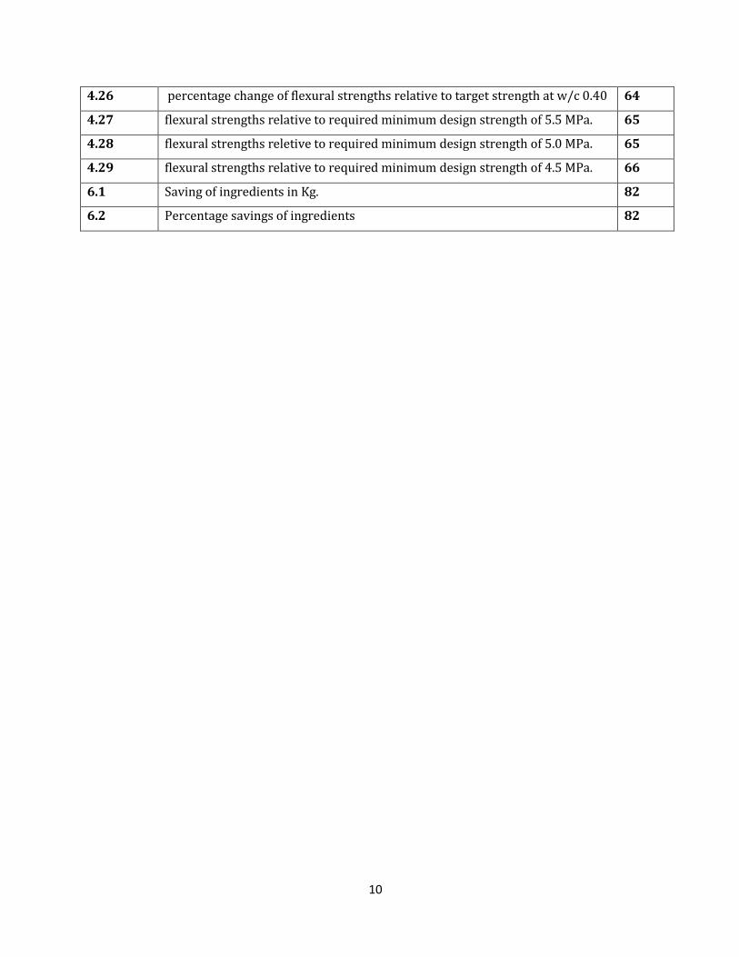
4.26 percentage change of flexural strengths relative to target strength at w/c 0.40 64
4.27 flexural strengths relative to required minimum design strength of 5.5 MPa. 65
4.28 flexural strengths reletive to required minimum design strength of 5.0 MPa. 65
4.29 flexural strengths relative to required minimum design strength of 4.5 MPa. 66
6.1 Saving of ingredients in Kg. 82
6.2 Percentage savings of ingredients 82
11
CHAPTER-1
INTRODUCTION
1.1 GENERAL
Concrete is basically a mixture of two components: Aggregates and Paste (or binder). The
paste comprises cement, supplementary cementing or supplementary cementitious materials and
water. It binds the aggregates (sand and gravel or crushed stone) into a rock-like mass. The purpose
is to fill up the voids and come with a dense and strong materials. The fine aggregates fill up the voids
formed by the coarse aggregates; and cement fills up the voids of the fine aggregates. Lesser the
voids more would be the strength of concrete. The chemical reaction of the cementitious materials
and water, is called hydration. It is the process by which paste hardens and binds the aggregates.
The high modulus of elasticity and rigidity of concrete compared to other road making
materials provides a concrete pavement with a reasonable degree of flexural or beam strength. This
property leads to a wider distribution of externally applied wheel loads. This in turn limits the
pressures applied to the sub-grade. The major portion of the load carrying capacity of a concrete
pavement is therefore provided by the concrete layer alone. Its thickness is primarily determined by
the flexural strength of the concrete and by the magnitude of the wheel or axle loads. Sub-bases do not
make a significant structural contribution to concrete pavements.
By contrast, a flexible pavement is a structure comprising a number of layers of bound or
unbound materials which can have a variety of surface treatments and in which the intensity of
stresses from traffic loads requires a lot more depth to diminish. Both the base and sub-base layers in
flexible pavements contribute significantly to the structural properties of the pavement. Concrete acts
more like a bridge over the sub-grade. Much less pressure is placed on the material below the
concrete, than bituminous pavements. Since the first strip of concrete pavement was completed in
1893, concrete has been now extensively used for paving the highways and airports as well as
business and residential streets.
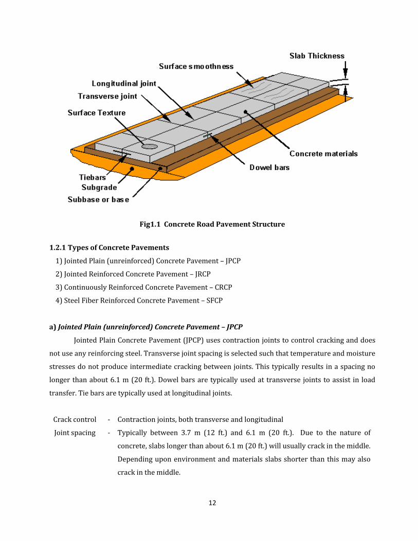
1.2 CONCRETE PAVEMENTS
A concrete pavement is a structure comprising of a layer of Ordinary Portland Cement
Concrete which is usually supported by a sub-base layer on the sub-grade. Concrete pavements may
be either unreinforced (plain) or reinforced depending on how the designer prefers to control
shrinkage cracking, which will occur in the pavements..
12
Fig1.1 Concrete Road Pavement Structure
1.2.1 Types of Concrete Pavements
1) Jointed Plain (unreinforced) Concrete Pavement – JPCP
2) Jointed Reinforced Concrete Pavement – JRCP
3) Continuously Reinforced Concrete Pavement – CRCP
4) Steel Fiber Reinforced Concrete Pavement – SFCP
a) Jointed Plain (unreinforced) Concrete Pavement – JPCP
Jointed Plain Concrete Pavement (JPCP) uses contraction joints to control cracking and does
not use any reinforcing steel. Transverse joint spacing is selected such that temperature and moisture
stresses do not produce intermediate cracking between joints. This typically results in a spacing no
longer than about 6.1 m (20 ft.). Dowel bars are typically used at transverse joints to assist in load
transfer. Tie bars are typically used at longitudinal joints.
Crack control - Contraction joints, both transverse and longitudinal
Joint spacing - Typically between 3.7 m (12 ft.) and 6.1 m (20 ft.). Due to the nature of
concrete, slabs longer than about 6.1 m (20 ft.) will usually crack in the middle.
Depending upon environment and materials slabs shorter than this may also
crack in the middle.
13
Reinforcement - None
Load transfer - Aggregate interlock and dowel bars. For low-volume roads aggregate interlock
is often adequate. However, high-volume roads generally require dowel bars
in each transverse joint to prevent excessive faulting.
b) Jointed Reinforced Concrete Pavement – JRCP
JRCP uses contraction joints and reinforcing steel to control cracking. Transverse joint
spacing is longer than that for concrete pavement contraction design (CPCD), it typically ranges from
30 ft. to 60 ft. This rigid pavement design option is no longer sanctioned by the department because
of past difficulties in selecting effective rehabilitation strategies. However, there are several
remaining sections in service.
Crack control - Contraction joints, Dowel bars as well as reinforcing steel.
Joint spacing - Longer than JPCP and up to a maximum of about 15 m (50 ft.). Due to the nature of concrete, the longer slabs associated with JRCP will crack
Reinforcement
Steel
- A minimal amount is included mid-slab to hold cracks tightly together. This can
be in the form of deformed reinforcing bars or a thick wire mesh.
Load transfer - Dowel bars assist in load transfer across transverse joints while reinforcing
steel assists in load transfer across mid-panel cracks
c) Continuously Reinforced Concrete Pavement - CRCP
Continuously Reinforced Concrete Pavement (CRCP) provides joint-free design i.e. it does not
require any construction joint. The formation of transverse cracks at relatively close intervals is a
distinctive characteristic of CRCP. These cracks are held tightly by the reinforcement and should be of
no concern as long as the cracks are uniformly spaced, do not spall excessively, and a uniform non-
erosive base is provided. Research has shown that the maximum allowable design crack width is
about 0.5 mm (0.02 inches) to protect against spalling and water penetration.
Crack control - Reinforcing Steel
Joint spacing - Not applicable. No transverse contraction joints are used.
Reinforcement
Steel
-
about 0.6 - 0.7 percent of the cross-sectional pavement area and is located near
mid-depth in the slab
Load transfer - Reinforcing steel
14
d) Steel Fiber Reinforced Concrete Pavement – SFCP
Steel fibers are used in the pavement quality concrete 0.5% to 1% weight of the cement. With
the inclusion of steel fibers the tensile and flexural strength of concrete increases considerably. It is
determined that there is considerable increase in flexural strength with the use of short, small
diameter of the steel fibers in the first crack ultimate flexural strength and flexural strength of plain
concrete. With the use of steel fibers, the ultimate strength can be increased up to 3 times the
strength of plain concrete.
It is determined that in the normal third-point bending test, the flexural strength of SFRC is about 50
to 70 percent more than that of the plain concrete mix. So with the inclusion of steel fibers the slab
thick gets reduced and hence is very economical.
The most significant influence of the incorporation of steel fibers in concrete is to delay and
control the tensile cracking of the composite material. This positively influences mechanical
properties of concrete. These improved properties resulting SFRC being a feasible material for
concrete road pavements.
1.2.2 Benefits of Concrete Pavements
The beneficial attributes of concrete pavements can be summarized as below:
1) Long lasting – 40 year Design Life
2) Heavy duty Pavements have generally the lowest cost.
3) Pavement maintenance costs are up to 10 times cheaper than the same for flexible
pavements.
4) Minimum maintenance requirements result in less traffic disruption, minimum congestion
time and results Work Zone safety.
5) Lowest Life Cycle Cost of all Heavy Duty pavements and highest salvage value.
6) Can be constructed over poor sub-grades.
7) Thinner overall pavement thickness = lower consumption of raw materials.
8) Resistant to abrasion from turning actions.
9) Not susceptible to high or low temperatures.
10) Not affected by weather, inert to spills and fire.
11) Completely recyclable.
12) High abrasion durability.
13) Profile durability.
15
14) Safer because it maintains its shape, no deformation, resistance to rutting and potholes and
excellent skid resistance.
15) High sustainability rating through use of local materials.
16) Use of waste products like fly-ash and slag.
17) Riding quality does not deteriorate.
18) Can be slip formed up to 13 m.
19) Saving of fuel costs of at least 1.1% over asphalt (VTI Sweden – 1.1% 2008, NRC Canada –
0.8 to 6.9%).
20) Light colour enhances night visibility.
21) Less energy for street lighting (up to 30%).
22) Less heat-sink effect (avg. 8°C lower than asphalt = less air conditioning energy in urban
areas).
23) Longitudinal diamond grinding, called Next Generation Concrete Surfacing (NGCS) now
provides quieter surface than for example Open Graded Asphalt overlay.
1.2.3 Demerits of Concrete Pavements
1) They involve heavy initial investment.
2) Lots of joints are need to provide which prove additional places of weakness.
3) 28 days curing is required after completion before they can be opened to traffic.
4) It is not possible to adopt stage construction programmed in these roads.
5) Cement concrete road surface after some time of use becomes very smooth and slippery.
6) It is a noisy road, as bullock carts or steel tyred vehicles cause lot of noise while moving on
them.
1.3 PAVEMENT QUALITY CONCRETE (PQC)
BRIEF AND DETAILED SPECIFICATIONS OF PAVEMENT QUALITY CONCRETE (PQC) AS PER MINISTRY
OF ROAD TRANSPORT AND HIGHWAYS [ MORT&H]
The purpose of this Quality Plan for Construction of Pavement Quality Concrete (PQC) is to
provide detailed Construction Methodology, Materials used, Resources deployed.
Cement Concrete Pavement
The work shall consist of construction of un-reinforced, dowel jointed, plain cement concrete
pavement in accordance with the requirements of these Specifications and in conformity with the
lines, grades and cross sections shown on the drawings. The work shall include furnishing of all plant
16
and equipment, materials and labour and performing all operations in connection with the work, as
approved by the Engineer.
1.3.1 Cement content :
When Ordinary Portland Cement (OPC) is used the quantity of cement shall not be less than
360 kg/cum. In case fly ash grade-I (as per IS:3812) is blended at site as partial replacement of
cement, the quantity of fly ash shall be up to 20 percent by weight of cement and the quantity of OPC
in such a blend shall not be less than 310 kg/cum. The minimum of OPC content in case ground
granulated Portland blast furnace is used, shall also not be less than 310 kg/m3.
1.3.2 Concrete strength:
The characteristic flexural strength of concrete shall not be less than 4.5 MPa (M 40 Grade).
Target mean flexural strength for mix design shall be more than 4.5 MPa + 1.65*s, where s is standard
deviation of flexural strength derived by conducting test on minimum 30 beams. While designing the
mix in the laboratory, correlation between flexural and compressive strengths of concrete shall be
established on the basis of at least thirty tests on samples. However, quality control in the field shall
be exercised on the basis of flexural strength. The water content shall be the minimum required to
provide the agreed workability for full compaction of the concrete to the required density and the
maximum free water cement ratio shall be 0.45 when only OPC is used and 0.50 when blended
cement (Portland Pozzolana Cement or Portland Slag Cement or OPC blended with fly ash or Ground
Granulated Blast Furnace Slag at site) is used.
1.3.3 Transverse joints:
Transverse joints shall be contraction and expansion joints constructed at the spacing
described in the drawings. Transverse joints shall be straight within the following tolerances along
the intended line of joints which is the straight line transverse to the longitudinal axis of the
carriageway at the position proposed by the Contractor and agreed to by the Engineer, except at road
junctions or roundabouts where the position shall be as described in the drawings:
i) Deviations of the filler board in the case of expansion joints from the intended line of the joint shall
not be greater than ± 10 mm.
ii) The best fit straight line through the joint grooves as constructed shall be not more than 25 mm
from the intended line of the joint.
17
iii) Deviations of the joint groove from the best fit straight line of the joint shall not be greater than 10
mm.
1.3.4 Contraction joints:
The contraction joints shall be placed transversely at pre-specified locations as per
drawings/design using dowel bars. These joints shall be cut as soon as the concrete has undergone
initial hardening and is hard enough to take the load of joint sawing machine without causing damage
to the slab Contraction joints shall consist of a mechanical sawn joint groove, 3 to 5 mm wide and
one-fourth to one-third depth of the slab ± 5 mm or as stipulated in the drawings and dowel bars
complying with Clause 602.6.5 of MoRT&H Specifications. Contraction joint shall be widened
subsequently accommodate the sealant as per Clause 602.11 of MoRT&H Specifications, to
dimensions shown on drawings or as per IRC:57
1.3.5 Expansion joints:
The expansion joints shall consist of a joint filler board complying with Clause 602.2.7 of
MoRT&H Specifications and dowel bars complying with Clause 602.6.5 of MoRT&H Specifications and
as detailed in the drawings. The filler board shall be positioned vertically with the prefabricated joint
assemblies along the line of the joint within the tolerances given in Clause 602.6.2.1 of MoRT&H
Specifications and at such depth below the surface as will not impede the passage of the finishing
straight edges or oscillating beams of the paving machines. The adjacent slabs shall be completely
separated from each other by providing joint filler board. Space around the dowel bars, between the
sub-base and the filler board shall be packed with a suitable compressible material to block the flow
of cement slurry.
1.3.6 Transverse construction joint:
Transverse construction joint shall be placed whenever concreting is completed after a day’s
work or is suspended for more than 30 minutes. These joints shall be provided at location of
constructing joints using dowel bars. The construction joints may preferably coincide with the pre-
specified location of construction joints by properly planning the day to day concreting work of PQC.
The joint shall be made butt type. At all construction joints, steel bulk heads shall be used to retain
the concrete while the surface is finished. The surface of the concrete laid subsequently shall conform
to the grade and cross sections of the previously laid pavement. When positioning of bulk head/stop-
end is not possible, concreting to an additional 1 or 2 m length may be carried out to enable the
movement of joint cutting machine so that joint grooves may be cut and the extra 1 or 2 m length is
18
cut out and removed subsequently after concrete has hardened. Like contraction joint, the
construction joint shall also be widened to dimensions as per IRC:57, not before 14 days curing of
PQC.
1.3.7 Longitudinal joint:
1) The longitudinal joints shall be saw cut as per details of the joints shown in the drawing or as per
dimensions given in IRC:57. The groove may be cut after the final set of the concrete. Joints
should be sawn to at least rd the depth of the slab ±5 mm as indicated in the drawing.
2) Tie bars shall be provided at the longitudinal joints as per dimensions and spacing shown in the
drawing and in accordance with Clause 602.6.6 of MoRT&H Specifications. Longitudinal joints
shall also be widened to dimensions as per IRC:57, not before 14 days curing of PQC.
1.4 SELECTION OF MATERIALS IN PQC AS PER MORTH SPECIFICATIONS.
Source of materials : The Contractor shall indicate to the Engineer the source of all materials to be
used in the concrete work with relevant test data sufficiently in advance, and the approval of the
Engineer for the same shall be obtained at least 45 days before the scheduled commencement of the
work in trial length. If the Contractor subsequently proposes to obtain materials from a different
source during the execution of main work, he shall notify the Engineer, with relevant test data, for his
approval, at least 45 days before such materials are to be used.
1.4.1 Cement : Any of the following types of cement capable of achieving the design strength may
be used with prior approval of the Engineer.
Table 1.1 Type of cement confirming to Indian standard code
S. No. Type Confirming to:
1 Ordinary Portland Cement 43 Grade IS:8112
2 Portland Blast Furnace Slag Cement IS:455
3 Portland Pozzolana Cement IS:1489-Part I
4 Ordinary Portland Cement 53 Grade IS:12269
1) Fly ash up to 20 percent by weight of cement may be used in Ordinary Portland Cement
53 Grade. No fly ash shall be used in any other grade of Cement other than 53 Grade. The fly
ash shall conform to IS:3812 (Part I).
19
2) Ground Granulated Blast Furnace Slag (GGBFS) obtained by grinding granulated slag
conforming to IS:12089. GGBFS shall not be used in any other grade of cement except 53
grade. The content of GGBFS shall be up to 50 percent by weight of Ordinary Portland
Cement 53 grade.
3) Site mixing of fly ash and ground granulated slag shall be permitted only after ensuring
availability of the equipments at site for uniform blending through a specific mechanized
facility with automated process control like batch mix plants conforming to IS:4925 and
IS:4926. Site mixing will not be allowed otherwise.
4) Mix design will be done as per IRC:44. The OPC content shall not be less than 310 kg/cum
in case of blending at site. The curing period may be suitably enhanced by at least about 2
days.
5) The Portland Pozzolana Cement produced in factory shall not have fly ash content more
than 25 percent. The Portland Pozzolana Cement produced in factory with fly ash content
more than 25 percent shall not be used. Certificate from the manufacturer to this effect shall
be procured before use.
If the soil around PQC has soluble salts like sulphates in excess of 0.5 percent, the cement used shall
be sulphate resistant and shall conform to IS:12330. Guidance may be taken from IRC:44 for
ascertaining the compressive/flexural strength of cement concrete required to match with the
prescribed design strength of concrete. Cement to be used may preferably be obtained in bulk form. If
cement in paper bags is proposed to be used, there shall be bag-splitters with the facility to separate
pieces of paper bags and dispose them off suitably. No paper pieces shall enter the concrete mix. Bulk
cement shall be stored in accordance with Clause 1014 of MoRT&H Specifications. The cement shall
be subjected to acceptance test just prior to its use.
1.4.2 Chemical Admixtures
Admixtures conforming to IS:9103 and IS:6925 shall be permitted to improve workability of
the concrete or extension of setting time, on satisfactory evidence that they will not have any adverse
effect on the properties of concrete with respect to strength, volume change, durability and have no
deleterious effect on steel bars. The particulars of the admixture and the quantity to be used, must be
furnished to the Engineer in advance to obtain his approval before use. Satisfactory performance of
the admixtures should be proved both on the laboratory concrete trial mixes and in the trial length
20
paving. If air entraining admixture is used, the total quantity of air in air-entrained concrete as a
percentage of the volume of the mix shall be 5±1.5 percent for 31.5 mm nominal size aggregate.
1.4.3 Fibers:
Fibers may be used subject to the provision in the design/approval by the Engineer to reduce
the shrinkage cracking and post-cracking. The fibers may be steel fiber as per IRC:SP:46 or polymeric
Synthetic Fibres within the following range of specifications:
Effective Diameter 10 micron – 1.0 mm
Length 6-48 mm
Specific gravity more than 1.0
Suggested dosage 0.6-2.0 kg/cum (0.2 -0.6 % by
weight of cement in mix).
[Usage will be regulated as
stipulated in IRC:44/IS:456 or any
other specialist literature.]
Water absorption less than 0.45 percent
Melting point of this fiber shall not be less than 160°C and the aspect ratio generally varies from 200
to 2000. These synthetic fibers will have good alkali and UV light resistance.
1.4.4 Aggregates
Aggregates for pavement concrete shall be natural material complying with IS:383 but with a Los-
Angeles Abrasion Test result not more than 35 percent. The aggregates shall be free from dirt, flint,
chalcedony or other silica in a form that can react with the alkalis in the cement. In addition, the total
chlorides content expressed as chloride ion content shall not exceed 0.06 percent by weight and the
total sulphate content shall not exceed 0.25 percent by weight.
Coarse aggregates : Coarse aggregates shall consist of clean, hard, strong, dense, non-porous and
durable pieces of crushed stone or crushed gravel and shall be devoid of pieces of disintegrated stone,
soft, flaky, elongated, very angular or splintery pieces. The maximum size of coarse aggregate shall
not exceed 31.5 mm for pavement concrete. No aggregate which has water absorption more than 2
percent shall be used in the concrete mix. The aggregates shall be tested for soundness in accordance
with IS:2386 (Part-5). After 5 cycles of testing, the loss shall not be more than 12 percent if sodium
21
sulphate solution is used or 18 percent if magnesium sulphate solution is used. The combined
flakiness and elongation index of aggregate shall not be more than 35 percent.
Fine aggregates : The fine aggregates shall consist of clean natural sand or crushed stone sand or a
combination of the two and shall conform to IS:383. Fine aggregate shall be free from soft particles,
clay, shale, loam, cemented particles, mica and organic and other foreign matter.
1.4.5 Water:
Water used for mixing and curing of concrete shall be clean and free from injurious amount of
oil, salt, acid, vegetable matter or other substances harmful to the finished concrete. It shall meet the
requirements stipulated in IS:456.
1.4.6 Mild steel bars for dowels and tie bars :
i) Dowel Bar shall be of plain mild steel conforming to IS:432 and will
have yield stress of Fe-240.
ii) Tie bar shall be of TMT steel conforming to IS:1786 and will have
yield stress of Fe-500.
1.4.7 Fly Ash
The fly ash, also known as pulverized fuel ash, Coal Fly ash (FA) is a by-product of the
combustion of pulverized coal in thermal power plants. It is removed by the dust collection systems
from the exhaust gases of fossil fuel power plants as very fine, predominantly spherical glassy
particles from the combustion gases before they are discharged into atmosphere. The size of particles
is largely dependent on the type of dust collection equipment . Diameter of fly ash particles ranges
from less than 1 μm to 150 μm. It is generally finer than Portland cement. The fly ash obtained from
electrostatic precipitators may have a specific surface of about 350000 to 500000 mm2/g, i.e. it is
finer than Portland cement. The fly-ash obtained from cyclone separators is comparatively coarser
and may contain larger amounts of un-burnt fuel. The chemical composition of fly ash is determined
by the types and relative amounts of incombustible material in the coal used. The major chemical
constituents in fly ash are silica, alumina and oxides of calcium and iron. Because of its fineness and
pozzolanic and sometimes self-cementitious nature, fly ash is widely used in cement and concrete.
Depending upon the collection system, varying from mechanical to electrical precipitators or
bag houses and fabric filters, about 85–99.9% of the ash from the flue gases in retrieved in the form of
fly ash. Fly ash accounts for 75–85% of the total coal ash, and the remainder is collected as bottom
22
ash or boiler slag . Fly ash because of its mineralogical composition, fine particle size and amorphous
character is generally pozzolanic and in some cases also self cementitious whereas bottom ash and
boiler slag are much coarser and are not pozzolanic in nature. Therefore, It is important to note that
all the ash is not fly ash and the fly ashes produced by different power plants are not equally
pozzolanic and, therefore, are not always suitable for use as mineral admixture in concrete. The major
components of fly ash reported in oxide form are silica (SiO2), alumina (Al2O3 ), and oxides of calcium
and iron (CaO and Fe2O3). Fly ash composition varies with the source of coal.
a) Utilization of Fly Ash in Cement and Concrete: Coal fly ash can be utilized in following ways.
High Volume Uses
High volume utilization of fly ash includes
- as structural fills in embankments, dams, dikes and levees, and
- as sub-base and base courses in road way construction.
Medium Volume Uses
This includes the use of fly ash
- as raw material in cement production
- as an admixture in blended cements and
- as replacement of cement or as a mineral admixture in concrete
- in addition coal ash including fly ash may be used as partial replacement of fine aggregate in
concrete
- for production of lightweight aggregates for concrete and many other applications.
Low Volume Uses
This includes the coal ash utilization
- in high value added applications such as metal extractions. High value metal recovery of Aluminum
(Al), Gold (Au), Silver (Ag), Vanadium (Va) and Strontium (Sr) fall in this category.
- Fly ash has potential uses for producing light weight refractory material and exotic high
temperature resistant tiles
- Cenospheres or floaters in fly ash are used as special refractory material and also as additives in
forging to produce high strength alloys.
Miscellaneous Uses
Based upon its physical properties, coal ash is used
- as land fill for land
- as filler in asphalt, plastics, paints and rubber products
23
- in water treatment and as absorbent for oil and chemical spills
Due to different densities of cement and fly ash 3100 to 3200 Kg/m3 and 2200 to 2400 kg/m3,
respectively, a part replacement by equal mass increases the volume of cementitious material, where
as replacement by equal volume reduces the mass. In practice the replacement is usually on a mass
basis. The use of fly ash influences the volume yield of concrete. It has little effect on the drying
shrinkage of concrete.
b) Classification of Fly Ash
As per ASTM C 618 (1993) specification for “Fly ash and raw or calcined natural pozzolan for
use as mineral admixture in Portland cement concrete,” pozzolans are defined as “silicious and
aluminous materials which in themselves possess little or no cementitious value but will, in finely
divided form and in the presence of moisture, chemically react with Ca(OH)2 at normal temperatures
to form compounds possessing cementitious properties.”
ASTM C 618 (1993) categorizes natural pozzolans and fly ashes into the following three categories.
Class-N: Raw or calcined natural pozzolans such as some ditomaceous earths, opaline chert and
shale, stuffs, volcanic ashes and pumice are included in this category. Calcined kaolin
clay and laterite shale also fall in this category of pozzolans.
Class-F: Fly ash normally produced from burning anthracite or bituminous coal falls in this category.
This class of fly ash exhibits pozzolanic property but rarely, if any, self hardening property.
Class-C: Fly ash normally produced from lignite or sub-bituminous coal is the only material included
in this category. This class of fly ash has both pozzolanic and varying degree of self-cementitious
properties. (Most Class-C fly ashes contained more than 15% CaO. But some Class-C fly ashes may
contain as little as 10% CaO).
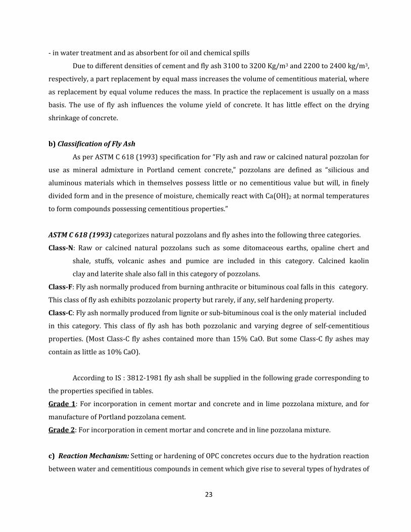
According to IS : 3812-1981 fly ash shall be supplied in the following grade corresponding to
the properties specified in tables.
Grade 1: For incorporation in cement mortar and concrete and in lime pozzolana mixture, and for
manufacture of Portland pozzolana cement.
Grade 2: For incorporation in cement mortar and concrete and in line pozzolana mixture.
c) Reaction Mechanism: Setting or hardening of OPC concretes occurs due to the hydration reaction
between water and cementitious compounds in cement which give rise to several types of hydrates of
24
calcium silicate (CSH), calcium aluminate (CAH) besides calcium hydroxide (CH). These hydrates are
generally called as ‘‘Tobermorite gel’’. The adhesive and cohesive properties of the gel bind the
aggregate particles. Calcium hydroxide is a by-product of cement hydration. When fly ash is
incorporated in concrete, the calcium hydroxide liberated during hydration of OPC reacts slowly with
the amorphous alumino-silicates, the pozzolanic compounds, present in the fly ash. The products of
these reactions, termed as pozzolanic reaction products, are time dependent but are basically of the
same type and characteristics as the products of the cement hydration. Thus additional cementitious
products become available which impart additional strength to concrete.
The following equations illustrate the pozzolanic reaction of fly ash with lime to produce
additional calcium silicate hydrate (C–S–H) binder:
Cement reaction: C3S + H --------hydration------> C-S-H + CaOH
Pozzolanic reaction : CaOH + S -------------> C-S-H
(silica from ash constituents)
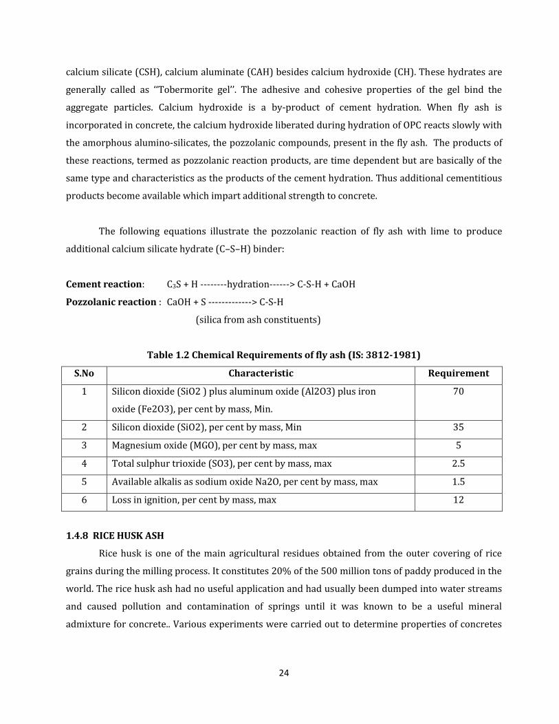
Table 1.2 Chemical Requirements of fly ash (IS: 3812-1981)
S.No Characteristic Requirement
1 Silicon dioxide (SiO2 ) plus aluminum oxide (Al2O3) plus iron
oxide (Fe2O3), per cent by mass, Min.
70
2 Silicon dioxide (SiO2), per cent by mass, Min 35
3 Magnesium oxide (MGO), per cent by mass, max 5
4 Total sulphur trioxide (SO3), per cent by mass, max 2.5
5 Available alkalis as sodium oxide Na2O, per cent by mass, max 1.5
6 Loss in ignition, per cent by mass, max 12
1.4.8 RICE HUSK ASH
Rice husk is one of the main agricultural residues obtained from the outer covering of rice
grains during the milling process. It constitutes 20% of the 500 million tons of paddy produced in the
world. The rice husk ash had no useful application and had usually been dumped into water streams
and caused pollution and contamination of springs until it was known to be a useful mineral
admixture for concrete.. Various experiments were carried out to determine properties of concretes
25
incorporating optimum RHA. Tests include compressive strength, splitting tensile strength,
workability, water permeability and flexural strength.
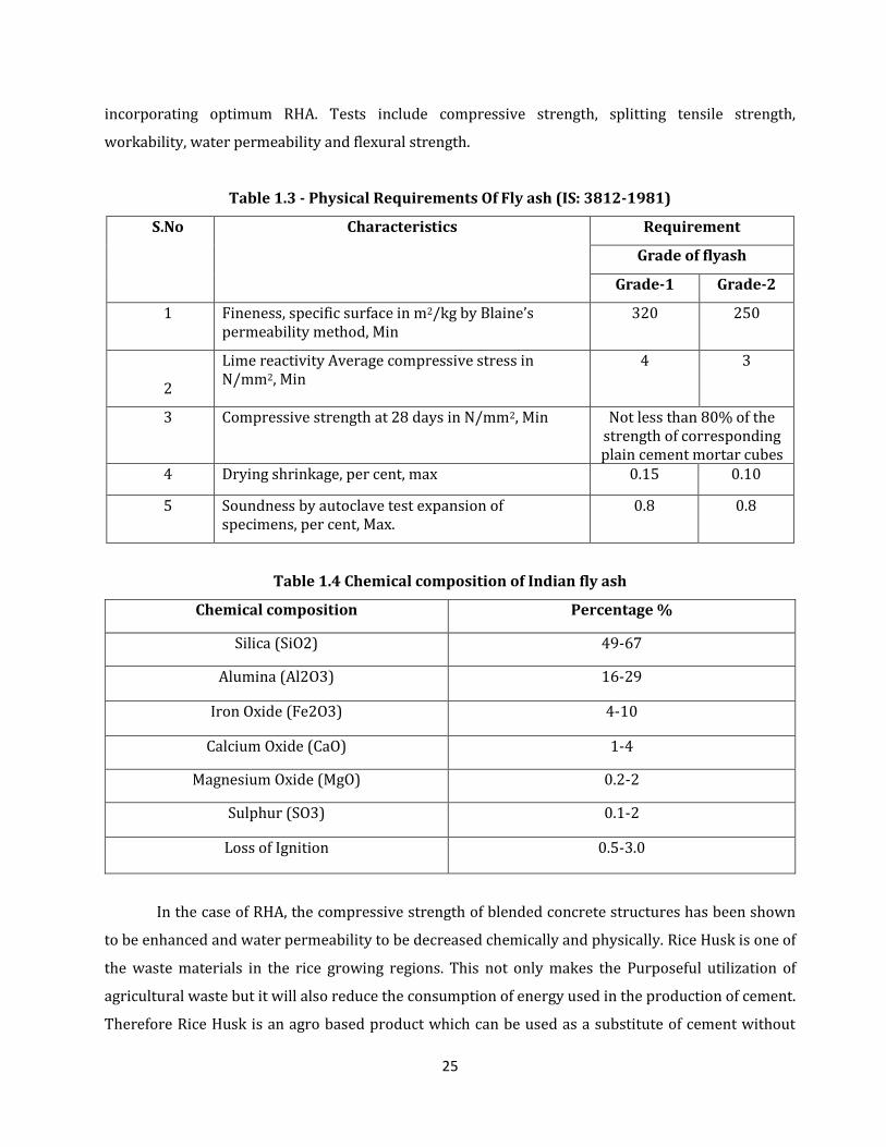
Table 1.3 - Physical Requirements Of Fly ash (IS: 3812-1981)
S.No
Characteristics
Requirement
Grade of flyash
Grade-1 Grade-2
1 Fineness, specific surface in m2/kg by Blaine’s permeability method, Min
320 250
2
Lime reactivity Average compressive stress in N/mm2, Min
4 3
3 Compressive strength at 28 days in N/mm2, Min Not less than 80% of the strength of corresponding plain cement mortar cubes
4 Drying shrinkage, per cent, max 0.15 0.10
5 Soundness by autoclave test expansion of specimens, per cent, Max.
0.8 0.8
Table 1.4 Chemical composition of Indian fly ash
Chemical composition Percentage %
Silica (SiO2) 49-67
Alumina (Al2O3) 16-29
Iron Oxide (Fe2O3) 4-10
Calcium Oxide (CaO) 1-4
Magnesium Oxide (MgO) 0.2-2
Sulphur (SO3) 0.1-2
Loss of Ignition 0.5-3.0
In the case of RHA, the compressive strength of blended concrete structures has been shown
to be enhanced and water permeability to be decreased chemically and physically. Rice Husk is one of
the waste materials in the rice growing regions. This not only makes the Purposeful utilization of
agricultural waste but it will also reduce the consumption of energy used in the production of cement.
Therefore Rice Husk is an agro based product which can be used as a substitute of cement without
26
sacrificing the strength and durability. Generally the Rice Husk Ash is used while burning the raw clay
bricks in the Brick Kilns. The calorific value varies with rice variety, moisture and bran content but a
typical value for husks with 8-10% moisture content and essentially zero bran is 15 MJ/kg. Rice Husk
Ash is obtained from burning of Rice Husk, which is the by-product of rice milling. It is estimated that
1000 kg of rice grain produce 200 kg of Rice Husk; after Rice Husk is burnt, about 20 percent of the
Rice Husk or 40 kg would become RHA. Rice Husk Ash contains as much as 80-85% silica which is
highly reactive, depending upon the temperature of incineration. However, the strength
characteristics are considered adequate for general masonry work. The utilization of rice husk ash as
a pozzolanic material in cement and concrete provides several advantages, such as improved strength
and durability properties, reduced materials costs due to cement savings, and environmental benefits
related to the disposal of waste materials and to reduced carbon dioxide emissions .Portland Rice
Husk Ash cements containing up to 50% Ash by weight showed compressive strengths which were
considerably higher than the control Portland cements even at early ages of 3 and 7 days. The
cements containing Rice Husk Ash possess excellent resistance to dilute organic and mineral acids.
The water demand for normal consistency tends to increase with increasing Ash content of the
blended cements. However, this can be corrected by application of certain water reducing
admixtures. The investigations as outlined above point towards encouraging trend. Reactions that
take place in the preparation of Rice Husk Ash concrete are; Silicon burnt in the presence of Oxygen
gives Silica.
Si + O2 --------►SiO2
C3 S (Cement) + H2O -----------► CSH + Ca (OH)2
The highly reactive silica reacts with Calcium hydroxide released during the hydration of cement,
resulting in the formation of Calcium Silicates responsible for strength.
SiO2 + Ca (OH)2 -----► CSH + SiO2
Physical Properties
Completely burnt rice-husk is grey to white in color, while partially burnt Rice Husk Ash is
blackish. Rice husk ash is a very fine material. The RHA samples are black with some gray particles,
resulting from different stages of the carbon combustion during burning of rice husk. The active silica
obtained after the heating and grinding presents reduced size of particles and grey coloration due to
27
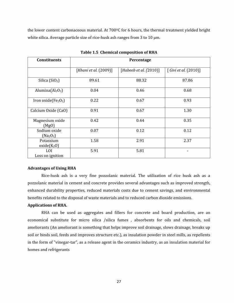
the lower content carbonaceous material. At 700OC for 6 hours, the thermal treatment yielded bright
white silica. Average particle size of rice-husk ash ranges from 3 to 10 µm.
Table 1.5 Chemical composition of RHA
Constituents Percentage
[Khani et al. (2009)] [Habeeb et al. (2010)] [ Givi et al. (2010)]
Silica (SiO2) 89.61
88.32 87.86
Alumina(Al2O3) 0.04 0.46 0.68
Iron oxide(Fe2O3) 0.22 0.67 0.93
Calcium Oxide (CaO) 0.91 0.67 1.30
Magnesium oxide (MgO)
0.42 0.44 0.35
Sodium oxide (Na2O3)
0.07 0.12 0.12
Potassium oxide(K2O)
1.58 2.91 2.37
LOI Loss on ignition
5.91 5.81 -
Advantages of Using RHA
Rice-husk ash is a very fine pozzolanic material. The utilization of rice husk ash as a
pozzolanic material in cement and concrete provides several advantages such as improved strength,
enhanced durability properties, reduced materials costs due to cement savings, and environmental
benefits related to the disposal of waste materials and to reduced carbon dioxide emissions.
Applications of RHA.
RHA can be used as aggregates and fillers for concrete and board production, are an
economical substitute for micro silica /silica fumes , absorbents for oils and chemicals, soil
ameliorants (An ameliorant is something that helps improve soil drainage, slows drainage, breaks up
soil or binds soil, feeds and improves structure etc.), as insulation powder in steel mills, as repellents
in the form of "vinegar-tar", as a release agent in the ceramics industry, as an insulation material for
homes and refrigerants
28
CHAPTER-2
LITERATURE REVIEW
The relevant literature pertaining to the use of Fly-Ash(FA) and Rice Husk Ash(RHA) in
concrete carried out in India and abroad has been reviewed and presented as under:-
2.1 FLY-ASH
2.1.1 Fresh Properties:
Low calcium Class F fly ash normally acts as a fine aggregate of spherical form in early stages
of hydration whereas high calcium Class-C fly ash may contribute to the early cementing reactions in
addition to its presence as fine particulate in the concrete mix. Hydration of cement is an exothermic
reaction and the released heat causes a rise of temperature of fresh concrete.
Brown, J.H. (1982) in his paper " The strength and workability of concrete with Fly Ash
substitution" conducted several studies with fly ash replacing cement and fine aggregate at levels of
10-40% by volume. He concluded that for each 10% of ash substituted for cement, the compacting
factor or workability changed to the same order as it would by increasing the water content of the
mix by 3-4%. When fly ash was substituted for sand or total aggregate, workability increased to reach
a maximum value at about 8% ash by volume of aggregate. Further substitution caused rapid
decrease in workability.
Gebler and Klieger, (1983) in their paper " Effect of fly ash on the air void stability of
concrete " investigated the requirements of Air Entraining Agent (AEA) for Class-C and Class-F fly
ashes. They reported that (1) concretes made with Class C fly ash generally require less AEA than
those made with Class F fly ashes; (2) for 6% air content in concrete, the AEA varied from 126 to
173% for fly ashes having more than 10% CaO, whereas it was in the range of 177 to 553% for fly
ashes containing less than 10% CaO; and (3) increase in both total alkalies and SO3 contents in fly ash
affect the air entrainment favorably. A concrete containing a Class F fly ash that has relative high CaO
content and less organic matter or carbon tends to be less vulnerable to loss of air.
Owens, (1989) in his paper" Fly ash and its usage in concrete" reported that with the use
of fly ash containing large fraction of particles coarser than 45µm or a fly ash with high amount of
unburned carbon, exhibiting loss on ignition more than 1%, higher water demand was observed.
Sivasundram, et al. (1990) in their paper " Selected properties of high volume fly ash
concretes" investigated the setting time of high-volume fly ash concrete mixes, and concluded that
29
the initial setting time of 1.50 hours was comparable to that of the control concrete, whereas the final
setting time was extended by about 3 hours as compared to that of the control concrete.
2.1.2 Hardened Properties:
Carette and Malhotra, (1983) in their research paper "Characterization of Canadian fly
Ashes and their Performance in Concrete" studied the effect of Canadian fly ashes on the
compressive strength of concrete mixes. Cement was replaced with 20% fly ash in all the mixes.
Compressive strength was measured up to the age of 365 days. It was seen that compressive strength
continued to increase with age, indicating pozzolanic action of fly ashes.
Joshi and Lohtia, (1993) in their paper " Effects of premature freezing temperatures on
compressive strength, elasticity and microstructure of high volume fly ash concrete" tested a
large number of fly concrete mixes made by using three different fly ashes containing about 10%
calcium oxide. The replacement level varied between 40 and 60% by weight of cement. The mixes
were super-plasticized and air-entrained to obtain 100 to 120 mm slump and 6 ± 1% air content. The
cementitious material content varied from 380 to 466 kg/m3, water to cementitious material ratio
from 0.27 to 0.37, coarse aggregate ranged from 1,012 to 1,194 kg/m3, and fine aggregate or sand
varied from 712 to 643 kg/m3. They reported that (1) at 7 days, the fly ash concretes obtained
strength between 27.9 and 41.0 MPa compared to 44.1 MPa of control concrete. However at the age
of 28 days, the fly ash concretes developed strength varying from 37.6 to 50.7 MPa against 58.7 MPa
for control concrete. At 120 days, strength of fly ash concrete ranged from 54.8 to 74.6 MPa whereas
it was 74.6 MPa of control concrete.
Lohtia et al. (1996) in his paper " Creep of fly ash concrete " studied the creep and creep
recovery of plain and fly ash concretes at stress-strength ratios of 20 and 35%. Fly ash content was
varied between 0 and 25%. They concluded that (1) replacement of 15% of cement with fly ash was
optimum with respect to strength, elasticity, shrinkage and creep of fly ash concrete; (2) creep–time
curves for plain and fly ash concretes were similar, and creep linearly related to the logarithm of
time; (3) with fly ash content up to 15%, increase in creep was negligible. However, slightly higher
creep occurred with fly ash content more than 15%; (4) creep coefficients were similar for the
materials with fly ash content in the range of 0–25%; and (5) creep recovery was found to vary from
22 to 43% of the corresponding 150-day creep. For replacement beyond 15%, the creep recovery was
smaller. No definite trend of creep recovery as a function of stress-strength ratio was observed.
Saraswathy et al. (2003) in their paper " Influence of activated fly ash on
corrosion–resistance and strength of concrete" investigated the influence of activated fly ash on
the compressive strength of concrete. Various activation techniques, such as physical, thermal and
30
chemical were adopted. Concrete specimens were prepared with 10, 20, 30 and 40% of activated fly
ash replacement levels with cement. Compressive strength was determined at 7, 14, 28 and 90 days.
They concluded that (1) activation of fly ash improved the strength of concrete. However, the
compressive strength of fly ash concrete was less than that of ordinary portland cement (OPC) even
after 90 days of curing; and (2) among the activation systems, chemically activated coal fly ash (CFA)
improved the compressive strength to a certain extent, only with 10 and 20% replacements. Since the
CFA surface layer is etched by a strong alkali to facilitate more cement particles to join together and
also the addition of CaO which is further promoting the growth of CSH gel and Ca(OH)2 which is more
advantageous to enhance the strength development.
Siddique, R. (2003) in his paper "Effect of fine aggregate replacement with class F fly
ash on the mechanical properties of concrete", studied the effect of partial replacement of fine
aggregate (sand) with varying percentages of Class F fly ash on the compressive strength, splitting
tensile strength, flexural strength and modulus of elasticity of concrete up to the age of 365 days. Fine
aggregate (sand) was replaced with five levels of percentages (10, 20, 30, 40, and 50%) of Class F fly
ash by weight. Control mix (without fly ash) was proportioned to have a 28-day cube compressive
strength of 26.4 MPa. Based on the results, it was concluded that (1) compressive strength of fine
aggregate (sand) replaced fly ash concrete specimens was higher than the plain concrete (control
mix) specimens at all the ages. The strength differential between the fly ash concrete specimens and
plain concrete specimens became more distinct after 28-days; (2) compressive strength continued to
increase with age for all fly ash replacement levels; (3) The maximum compressive strength occurs
with 50% fly ash content at all ages. It was 40.0 MPa at 28-day, 51.4 MPa at 91-day, and 54.8 MPa at
365-day. (4) splitting tensile strength, and flexural strength of fine aggregate (sand) replaced fly ash
concrete specimens was higher than the plain concrete (control mix) specimens at all the ages. The
strength differential between the fly ash concrete specimens and plain concrete specimens became
more distinct after 28-days; (5) both splitting and flexural strengths continued to increase with age
for all fly ash percentages; (6) at all the ages, the maximum splitting tensile strength was observed
with 50% fly ash content. It was 3.5 MPa at 28-day, 4.3 MPa at 91-day, and 4.4 MPa at 365-day; (7)
maximum flexural strength was found to occur with 50% fly ash content at all ages. It was 4.3 MPa at
28-day, 5.2 MPa at 91-day, and 5.4 MPa at 365-day. (8) modulus of elasticity of fine aggregate (sand)
replaced fly ash concrete specimens was higher than the plain concrete (control mix) specimens at all
the ages. The differential between the fly ash concrete specimens and plain concrete specimens
became more distinct after 28-days; (9) modulus of elasticity of fine aggregate (sand) replaced fly ash
concrete continued to increase with age for all fly ash percentages; and (10) at all ages, the maximum
31
value of modulus of elasticity occurs with 50% fly ash content. It is 24.5 GPa at 28-day, 28.0 GPa at
91-day, and 29.0 GPa at 365-day.
Atis et al. (2004) in their paper " Strength and shrinkage properties of mortar
containing a nonstandard high-calcium fly ash" assessed the drying shrinkage of mortar mixtures
containing high calcium non standard fly ash up to the age of 5 months. Five mortar mixtures
including control Portland cement and fly ash mortar mixtures were prepared. Fly ash replaced
cement on mass basis at the replacement ratios of 10, 20, 30 and 40%. Water–cementitious materials
ratio was 0.4. Mixtures were cured at 65% relative humidity and 20 ± 2O C. They reported that
shrinkage of Portland cement mortar at 5 months was 0.1228%. Shrinkage of fly ash mortar
decreased with the increase in fly ash content. Shrinkages of mortar containing 10, 20 and 30% fly
ash were 25, 37 and 43%, lower than the shrinkage of Portland cement mortar at the end of 5
months. The reduction in shrinkage with the use of fly ash in mortar could be explained by the
dilution effect of fly ash. The expansive property of fly ash most probably contributed to the reduction
in drying shrinkage.
Demirboga et al. (2007) in their paper "Thermo-mechanical properties of concrete
containing high-volume mineral admixtures" investigated the Thermal Conductivity (TC) of HVFA
concrete at the age of 28 days. Cement was replaced with 0, 50, 60, and 70% of Class C fly ash. They
concluded that TC of concrete decreased to 32, 33, and 39% for 50, 60 and 70% fly ash replacement,
respectively.
2.1.3 Durability Properties:
Ho and Lewis, (1983) in their paper " Carbonation of concrete incorporating fly ash or a
chemical admixture", investigated the carbonation rates of three types of concrete mixes (1) plain
concrete; (2) the second containing a water reducing admixture; and (3) third in which fly ash was
used to replace part of the cement. Accelerated carbonation was induced by storing specimens in an
enriched CO2 atmosphere (4%) at 20_C and 50% RH for 8 weeks. One week under these conditions
was approximately equivalent to 1 year in a normal atmosphere (0.003% CO2). They concluded that
(1) concretes having the same strength and water-to-cement ratio do not necessarily carbonate at the
same rate; (2) concrete containing fly ash showed significant improvement in quality when curing
was extended from 7 to 90 days. This improvement was much greater than that achieved for the plain
concrete; and (3) depth of carbonation is a function of the cement content for concretes moist-cured
for 7 days. However, with further curing to 90 days, concrete containing fly ash showed a slower rate
of carbonation as compared to plain and water-reduced concretes.
32
Virtanen, J. (1983) in his paper " Freeze–thaw resistance of concrete containing blast
furnace slag, fly ash or condensed silica fume" evaluated the freezing and thawing resistance
concrete made with fly ash. They concluded that (1) air content has the greatest influence on the
freeze–thaw resistance of concrete; (2) addition of fly ash had no major influence on the freeze–thaw
resistance of concrete if the strength and air content are kept constant.
Naik et al., (1994) in their research " Permeability of concrete containing large amounts
of fly ash" evaluated the influence of addition of large amounts (50 and 70% cement replacement) of
Class C fly ash on the chloride permeability of concrete. Concrete mixtures were designated as C-3
(0% fly ash), P4-7 (50% fly ash) and P4-8 (70% fly ash). Chloride permeability was determined in
accordance with ASTM C1202, Chloride permeability decreased with age. At the age of 2 months, all
concrete mixtures except the 70% fly ash mixture exhibited moderate (2,000–4,000 C) permeability
in accordance with ASTM C1202 specifications. The 50% fly ash concrete mixture showed lower
permeability relative to the no-fly ash concrete at all ages. The 70% fly ash mixture also performed
better than that of the no-fly ash concrete after 3 months.
Mehta, P.K. (2000) in his paper " Sulfate Attack on concrete." concluded that fly ashes are
amongst the group of pozzolans that significantly increase the life expectancy of concrete exposed to
sulfate attack. In general, Class F type fly ash meeting the specification requirements will improve the
sulfate resistance of any concrete/mortar mix in which it is included, although the degree of
improvement may vary with either the cement used or the fly ash. The situation with Class C fly ash is
different. A few studies indicated that some Class C fly ashes may rather reduce sulfate resistance
when used in normal proportions
Siddique, R. (2003) in his paper " Effect of fine aggregate replacement with class F fly
ash on the abrasion resistance of concrete " studied the abrasion resistance of concrete
proportioned to have four levels of fine aggregate replacement (10, 20, 30 and 40%) with Class F fly
ash. A Control mixture with ordinary Portland cement was designed to have 28 days compressive
strength of 26 MPa. Concrete specimens of size 65 9 65 9 60 mm were made for the purpose. The
abrasion resistance of concrete mixtures was determined at the ages of 28, 91, and 365 days in
accordance with Indian Standard Specifications. It was measured in term of depth of wear. The
variation of depth of wear versus percentage of fine aggregate replacement with Class F fly ash, at 60
min of abrasion time concluded that with the increase in fly ash content, depth of wear decreased,
which indicated that the abrasion resistance of concrete increased with the increase in fly ash
content. This showed that for a particular percentage of fine aggregate replacement with fly ash,
depth of wear decreased with increase in age, which means that abrasion resistance increased with
33
age. This could be primarily attributed to the increase in compressive strength resulting from
increased maturity of concrete with age.
Chalee et al. (2007) in their paper " Effect of W/C ratio on covering depth of fly ash
concrete in marine environment" studied the effect of W/C ratio on covering depth required
against the corrosion of embedded steel of fly ash concrete in marine environment up to 4-year
exposure. Fly ash was used to partially replace Portland cement type I at 0, 15, 25, 35, and 50% by
weight of cementitious material. Water-to-cementitious material ratios (w/c) of fly ash concretes
were varied at 0.45, 0.55, and 0.65. Tests were conducted for corrosion of embedded steel bar after
being exposed to tidal zone for 2, 3, and 4 years. Based on the tests, they concluded that (1) covering
depth required for the initial corrosion of embedded steel bar in concrete could be reduced with fly
ash; (2) decrease in W/C ratio resulted in reducing the covering depth required for initial corrosion,
and generally affected the cement concrete rather than the fly ash concrete; (3) fly ash concretes with
35 and 50% replacements and W/C ratio of 0.65, provided the result of corrosion resistance at 4-year
exposure as good as cement concrete with W/C ratio of 0.45; and (4) concrete with compressive
strength of 30 MPa could reduce the covering depth from 50 to 30 mm by using fly ash to replace
Portland cement of 50%.
2.2 RICE HUSK ASH:
2.2.1 Fresh Properties:
Zhang and Malhotra, (1996) in their paper " High-performance concrete incorporating
rice husk ash as a supplementary cementing material" investigated the influence of RHA on the
air-entraining admixture (AEA) requirement of concrete mixtures made with RHA (0, 5, 8, 10 and
15%) as partial replacement of cement. It was observed that AEA requirement increased with the
increase in RHA content possibly because of high specific surface area of RHA in comparison to
cement.
Bui et al. (2005) in their paper “ Particle Size Effect On The Strength Of Rice Husk Ash
Blended Gap-Graded Portland Cement Concrete.” investigated the workability of concrete and
super plasticizer content to be added when cement is replaced by RHA in gap graded concrete. Two
kinds of an ordinary Portland cement were employed, i.e., PC30 and PC40. Twenty four concrete
mixtures were made, 12 mixtures for each of the two kinds of PC. Three levels of the water to binder
ratio were investigated, i.e., 0.30, 0.32 and 0.34. The mixtures with water to binder ratio of 0.30 were
made with a binder content of 550kg/m3 concrete. The binder content of all other mixtures was
34
500kg/m3. Rice husk ash was used to replace 10%, 15% and 20% by mass of PC. The super plasticizer
was added to all mixtures for obtaining high workability. In the mixtures with water to binder ratio of
0.34, the amount of super plasticizer was kept constant to investigate the influence of RHA on
workability All the mixtures have high slump values and they all are stable. A reduction in slump of
the blended concrete mixtures is found when a part of the PC is replaced by RHA at equal super
plasticizer content. This decline in slump increases with replacement level of cement by RHA. The
finer cement (PC40) requires a higher super plasticizer dosage for achieving equal slump. For the
plain (PC30) concrete, a super plasticizer dosage of 1% by mass of the cement is required to attain a
slump of 210mm. In case of the finer cement (PC40), the super plasticizer dosage is increased to
1.28% for obtaining approximately the same slump.
Ganesan et al. (2008) in his paper " Rice husk ash blended cement: assessment of
optimal level of replacement for strength and permeability properties of concrete" reported
the effect of cement replacement with RHA on the consistency and setting times of cement.
Percentages of cement replacement were 0, 5, 10, 15, 20, 20, 25, 30, and 35. They observed that
consistency of control mixture was approximate 32%, however, water required for standard
consistency linearly increased with an increase in RHA content. The standard consistency with 35%
RHA content was 44%. As ashes are hygroscopic in nature and the specific surface area of RHA is
much higher than cement, it needs more water. The results of initial and final setting times are shown
in Fig. 5.10. It was observed that up to 15%, RHA level increased the initial setting time. At 20, 25, 30
and 35%, there was reduction in initial setting time. The initial setting time measured for RHA
blended cements up to 35% was higher than that of control OPC. On the other hand, the final setting
time decreased with the increase in RHA up to 35%.
Khani et al. (2009) in their paper " The Effect of Rice Husk Ash on Mechanical Properties
and Durability of Sustainable Concretes." studies the surface water absorption in rice husk ash
concrete in comparison to controlled concrete. A total of 4 concrete mixtures were made; one
corresponding to a control concrete (CTL) and three others with 7%, 10% and 15% RHA Replaced
with cement by weight. Concrete cubes of 100×100×100 mm dimension were cast for water
penetration tests. In this test, water was forced into the concrete samples from one side for three
days and under constant pressure of 0.5 MPa. Then, the samples were split in a plane parallel to the
direction of water penetration, and the greatest depth of water penetration into the concrete sample
was measured. Depth of water penetration of concrete specimens decreased significantly with an
increasing in RHA content and curing period.
35
Givi et al. (2010) in their paper “Assessment of the effects of rice husk ash particle size
on strength, water permeability and workability of binary blended concrete.” investigated the
workability of concrete by partial replacement of cement with agro-waste rice husk ash. Standard
slump tests were used to determine the workability of the concrete. Two types of rice husk ash with
average particle size of 5 micron (ultra fine particles) and 95 micron and with four different contents
of 5%, 10%, 15% and 20% by weight were used. Result shows the influence of RHA content and
particle fineness on the workability of mixtures at constant water to binder ratio of 0.40. Unlike the
C0 series, all investigated RHA blended mixtures had acceptable workability with high slump (more
than 6.5 cm) values. Partial replacement of cement by RHA improved workability of fresh concrete
for both used average particle sizes. However, the RHA with average particle size of 95 μm gave rise
to higher slump values for comparable cases.
Habeeb et al. (2010) in their paper "Study on Properties of Rice Husk Ash and Its Use as
Cement Replacement Material" investigates the workability, fresh density and super plasticizer
content of rice husk ash (RHA) produced by using a Ferro-cement furnace. The slump was in the
range of 200 – 240 mm, bleeding was negligible for the control mixture. For concretes incorporating
RHA, no bleeding or segregation was recorded. The fresh density was in the range of 2253 to 2351
kg.m-3, the lowest density values were for 20F1 mixture. The concretes incorporating finer RHA
resulted in denser concrete matrix. SP content has to be increased along with the RHA fineness and
content due to the high specific surface area of RHA which would increase the water demand,
therefore, to maintain high workability, SP content rose up to 2% for the 20F3 mixture.
Uduweriya et al. (2010) in their paper " Investigation of Compressive Strength of
Concrete Containing Rice-Husk-Ash " investigated surface absorption of rice husk ash concrete
(20% RHA), fly ash concrete (20% FAC) and combination of rice husk and fly ash in concrete
(10%RHA + 10%FAC). The surface water absorption test was carried out with a concrete cube of
150x150x150 mm size. The W/C ratio of 0.75 was used for concrete mixture. The surface water
absorption of concrete was tested at 10, 30 and 60 min after the water head was released to the
concrete surface.
The concrete containing RHA has shown a considerable reduction in surface water absorption in
concrete. Further addition of fly ash has given better result than the 20% RHA replacements
Tashima et al. (2010) in their paper " The Possibility Of Adding The Rice Husk Ash (RHA)
To The Concrete.", evaluates how different contents of rice husk ash (RHA) added to concrete may
influence its physical and mechanical properties like surface water absorption. Samples with
dimensions of 10 X 20 cm were tested, with 5% e 10% of RHA, replacing in mass the cement. Three

36
mixtures were made i.e. Mixture D (controlled mix), Mixture E (5% replacement) , Mixture F (10%
replacement). The results reveal that higher substitution amounts results in lower water absorption
values, it occurs due to the RHA that is finer than cement. Adding 10% of RHA to the concrete, a
reduction of 38.7% in water absorption is observed when compared to mixture D.
Nagrale et al. (2012) in their paper " Utilization of Rice Husk Ash" studied various
properties like workability of the concrete mix when we replace cement by 15% RHA compared to
our normal ordinary Portland cement concrete mix. The fine aggregate used is natural sand
conforming to Zone II & standard sand of Grade 2. The coarse aggregate used are of sizes 20 mm and
12.5mm. Cement used is of 43 grade. The mix proportion used is M20. Three w/c ratios were used i.e.
0.45, 0.5, 0.6. The Concrete Slump values decreases with the addition of RHA. This means that a less
workable (stiff) mix is obtained when RHA is used as a cement blender. More water is therefore
required to make a workable mix. The increased fines in the concrete due to excess RHA is partly
responsible for this increased demand of water. Water Absorption tests reveal that higher
substitution amounts results in lower water absorption values which is due to RHA being finer than
cement. The use of RHA considerably reduces the water absorption of concrete. Thus, concrete
containing RHA can be effectively used in places where the concrete can come in contact with water
or moisture.
2.2.2 Hardened Properties
Zhang et al. (1996) in their paper " Rice husk ash blended cement: assessment of optimal
level of replacement for strength and permeability properties of concrete", this paper presents
an experimental study on the effects of the incorporation of rice-husk ash (RHA) in cement concrete
on the compressive strength of concrete is discussed, and the results are compared with those
obtained with the control Portland cement concrete and concrete incorporating silica fume. Three
types of mixes were made. The RHA and the control concrete had similar one-day strengths, but the
RHA concrete had Somewhat higher strength than the control concrete thereafter up to 180 days.
Compared with the silica fume concrete, the compressive strength of the RHA concrete was lower up
to 28 days, but similar at 90 and 180 days.
Bui et al. (2004) in their paper " Concrete Incorporating Rice-Husk Ash: Compressive
Strength and Chloride-Ion Penetrability " investigated the compressive strength of the mix when
cement is replaced by RHA in gap graded concrete. Two kinds of an ordinary Portland cement were
employed, i.e., PC30 and PC40. Twenty four concrete mixtures were made, 12 mixtures for each of the
two kinds of PC. Three levels of the water to binder ratio were investigated, i.e., 0.30, 0.32 and 0.34.
37
The mixtures with water to binder ratio of 0.30 were made with a binder content of 550kg/m3
concrete. The binder content of all other mixtures was 500kg/m3. Rice husk ash was used to replace
10%, 15% and 20% by mass of PC. Cubes of 100mm size were cast and compacted in two layers on a
vibrating table. Compressive strength of the concretes was determined at 1, 3, 7, 28 and 90 days,
using three specimens per test. Compressive strength of RHA blended concrete is higher than those of
the plain cement concrete, irrespective of water to binder ratio and age. Compressive strength
increases with blending percentage at corresponding values of water to binder ratio and age. Higher
contents of RHA can be used without a strength loss. This will, however, cause an increase in the
super plasticizer dosage required. The RHA blending increases the relative strength at all ages,
however, most pronounced is the increase in the first 7 days. Concretes made with the fine cement
(PC40) revealed considerable higher strengths than those made with the coarser cement (PC30).
Partial cement replacement by RHA also significantly improved strength, although the effect was
pronounced only at later ages. The compressive strength values of RHA blended concrete to be lower
than those of plain cement concretes at ages up to 3 days. However, at later age, say from 7 days
onward, the blended concretes have higher compressive strength than those of the control concretes.
Khani et al. (2009) in their paper " The Effect of Rice Husk Ash on Mechanical Properties
and Durability of Sustainable Concretes", investigated split tensile strength of the concrete
incorporating rice husk ash of 7%, 10% and 15% by weight of cement. Two 150 X 300 mm cylindrical
concrete specimen was prepared for the test. Concrete containing RHA has a greater splitting tensile
strength than that the control concrete at all ages. It is clear that, as the amount of RHA increases, the
tensile strength increases up to 20%. For instance, at 90 days the 15%RHA concrete had a tensile
strength of 5.62 MPa compared with 4.58 MPa for the control concrete. Concrete cubes of
100×100×100 mm dimension were cast for compressive strength. RHA concrete had higher
compressive strengths at various ages and up to 90 days when compared with the control concrete.
The results show that it was possible to obtain a compressive strength of as high as 46.9 MPa after 28
days. In addition, strengths up to 63.2 MPa were obtained at 90days
Rukzon et al. (2010) in their paper " Strength and Carbonation Model of Rice Husk Ash
Cement Mortar with Different Fineness", studied the compressive strength properties of mortar
mix with the addition of rice husk ash. Three finenesses of rice husk ashes, viz., original rice husk ash
RAO with 70% retained on sieve number 325, medium rice husk ash RA1 with 15–20% by weight
retained on a sieve No. 325, and fine rice husk ash RA2 with 1–3% by weight retained on a sieve No.
325. Ordinary Portland cement was partially replaced with RAO, RA1, and RA2 with 0 to 40 % . The
compressive strengths were tested at the age of 3, 7, 28, 60, 90, and 180 days. The compressive
38
strength of mortar containing RAO (20RAO and 40RAO) was lower than that of the control mortar
(OPC) at all ages. The compressive strength of mortar was reduced with an increase in dosage of rice
husk ash. The use of RA1 resulted in an increase in the strength as compare to RAO at all ages. For
RA2, the results showed that higher compressive strength was developed due to the high fineness of
RA2 and a decrease in the water requirement. the replacement of portland cement Type I with rice
husk ash decreases the compressive strength . An increase of rice husk ash fineness increases the
strength.
Habeeb et al. (2010) in their paper " Study on Properties of Rice Husk Ash and Its Use as
Cement Replacement Material " investigates the compressive strength of rice husk ash (RHA)
produced by using a Ferro-cement furnace. Mixture proportioning was performed to produce high
workability concrete (200 – 240 mm slump) with target strength of 40 MPa for the control mixture. A
total of 13 concrete mixtures were casted to study compressive strength of RHAC and results were
seen for 1, 3, 7 and 28 days. F1, F2, F3 represents the grinding time that is 180 min, 270 min and 360
min respectively . The results showed that at early ages the strength was still comparable, while at
the age of 28 days, finer RHA concrete exhibited higher strength than the concrete with coarser RHA.
The 5% replacement level achieved slightly lower values of compressive strength at early ages for up
to 7 days except for the 05% replaced F3 mixture where the compressive strength was higher due to
the increased reactivity and the filler effect of RHA. Based on that, it can be noticed that the amount of
RHA present when 5% replacement used is not adequate to enhance the strength significantly. The
strength increased with RHA for up to 10% which resulted in achieving the maximum value. When
20% of OPC was replaced for RHA, the strength of concrete achieved equivalent values to the OPC
control mixture.
Givi et al. (2010) in their paper " Assessment of the effects of rice husk ash particle size
on strength, water permeability and workability of binary blended concrete." studies the
compressive strength of concrete by partial replacement of cement with agro-waste rice husk ash.
Two types of rice husk ash with average particle size of 5 micron (ultra fine particles) and 95 micron.
A total of three series of mixtures were prepared in the laboratory trials. The control mixtures were
made of natural aggregates, cement and water. RHA with average particle sizes of 95 and 5 μm (ultra
fine particles), the mixtures were prepared by replacing 5%, 10%, 15% and 20% of cement with RHA.
Cubes of 100 mm edge were cast and compacted in two layers on a vibrating table. The results show
that the RHA-blended concrete had higher compressive strength at 90 days in comparison with that
of the concrete without RHA, although at 7 and 28 days different behaviors were observed between
the concretes with the two RHA considered. It is found that the cement could be advantageously
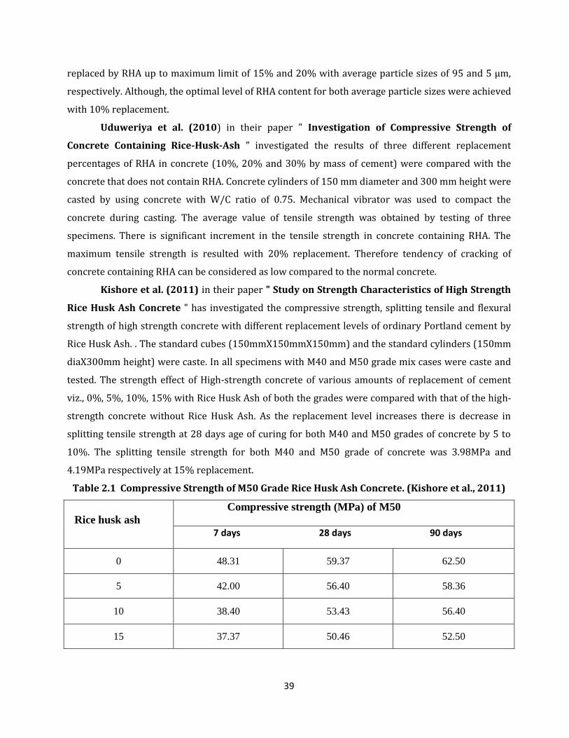
39
replaced by RHA up to maximum limit of 15% and 20% with average particle sizes of 95 and 5 μm,
respectively. Although, the optimal level of RHA content for both average particle sizes were achieved
with 10% replacement.
Uduweriya et al. (2010) in their paper " Investigation of Compressive Strength of
Concrete Containing Rice-Husk-Ash " investigated the results of three different replacement
percentages of RHA in concrete (10%, 20% and 30% by mass of cement) were compared with the
concrete that does not contain RHA. Concrete cylinders of 150 mm diameter and 300 mm height were
casted by using concrete with W/C ratio of 0.75. Mechanical vibrator was used to compact the
concrete during casting. The average value of tensile strength was obtained by testing of three
specimens. There is significant increment in the tensile strength in concrete containing RHA. The
maximum tensile strength is resulted with 20% replacement. Therefore tendency of cracking of
concrete containing RHA can be considered as low compared to the normal concrete.
Kishore et al. (2011) in their paper " Study on Strength Characteristics of High Strength
Rice Husk Ash Concrete " has investigated the compressive strength, splitting tensile and flexural
strength of high strength concrete with different replacement levels of ordinary Portland cement by
Rice Husk Ash. . The standard cubes (150mmX150mmX150mm) and the standard cylinders (150mm
diaX300mm height) were caste. In all specimens with M40 and M50 grade mix cases were caste and
tested. The strength effect of High-strength concrete of various amounts of replacement of cement
viz., 0%, 5%, 10%, 15% with Rice Husk Ash of both the grades were compared with that of the high-
strength concrete without Rice Husk Ash. As the replacement level increases there is decrease in
splitting tensile strength at 28 days age of curing for both M40 and M50 grades of concrete by 5 to
10%. The splitting tensile strength for both M40 and M50 grade of concrete was 3.98MPa and
4.19MPa respectively at 15% replacement.
Table 2.1 Compressive Strength of M50 Grade Rice Husk Ash Concrete. (Kishore et al., 2011)
Rice husk ash
Compressive strength (MPa) of M50
7 days 28 days 90 days
0 48.31 59.37 62.50
5 42.00 56.40 58.36
10 38.40 53.43 56.40
15 37.37 50.46 52.50
40
It shows that the splitting tensile strength at 15% replacement decreased by 5.1% for M40 grade of
concrete and 9.1% for M50 grade of concrete, when compared with that of the conventional concrete.
Maximum value is obtained by M50 grade concrete with 5% replacement. The compressive strength
at 7, 28 and 56 days have been obtained. Replacement of cement with Rice Husk Ash leads to
decrease in the compressive strength for both M40 and M50 mixes. He observed that for both grade
of concretes the flexural strengths were decreased at 15% replacement of rice husk ash with cement,
but obtained target strength at 10% replacement.
Khan et al. (2012) in their paper " Reduction in environmental problems using rice-husk
ash in concrete " studied the flexural strength of RHAC. Test was carried out on RHAC concrete
beams containing 0%, 25%, 30% and 40% of RHA as a replacement of OPC All the concrete beams
were cast in 1:2:4 mixture design ratio of Cement: sand: coarse aggregate, respectively. A midpoint
loading was applied. The load taken by pure OPC concrete beams was greater than the RHAC concrete
beams both at first crack development and failure. The deflection at mid span decreased with the
increase of RHA content in RHAC concrete beams both at first crack development and at failure. For
25% RHAC concrete beam the mid span deflection at failure load is 32 mm as compared to 38 mm for
OPC concrete beam. For 25% OPC replacement with RHA, the beam performed very well in flexure.
The failure load for 25% RHAC is 51 KN which is quite close to 54 KN for OPC concrete beam.
Tashima et al. (2012) in their paper " The Possibility Of Adding The Rice Husk Ash (RHA)
To The Concrete " evaluates how different contents of rice husk ash (RHA) added to concrete may
influence its physical and mechanical properties like splitting tensile strength. Samples with
dimensions of 10 X 20 cm were tested, with 5% e 10% of RHA, replacing in mass the cement. Three
mixtures were made i.e. Mixture D (controlled mix) , Mixture E (5% replacement) , Mixture F (10%
replacement). All the replacement degrees of RHA researched, achieve similar results in splitting
tensile strength. According to the results, may be realized that there is no interference of adding RHA
in the splitting tensile strength. There is slight increase in the split tensile strength if compared to
controlled mix. The addition of RHA causes an increment in the compressive strength due to the
capacity of the pozzolan, of fixing the calcium hydroxide, generated during the reactions of hydrate of
cement. All the replacement degrees of RHA increased the compressive strength. For a 5% of RHA,
25% of increment is verified when compared with mixture D.
41
CHAPTER-3
MATERIAL AND DESIGN METHODOLOGY
3.1 GENERAL
The present chapter deals with the presentation of results obtained from various tests
conducted on materials used for developing concrete. In order to achieve the objectives of present
study, an experimental program was planned to investigate the effect of Fly Ash, Rice Husk Ash on
Compressive Strength, and Flexural Strength of pavement quality concrete.
3.2 MATERIALS
The properties of material used for making concrete mix are determined in laboratory as per
relevant code of practice. Different materials used in present study were cement, coarse aggregates,
fine aggregates, fly ash and rice husk ash. Description of various materials which were used in this
study is given below:
3.2.1 Cement
Although all materials that go into concrete mix are essential, cement is very often the most
important because it is usually the delicate link in the chain. The function of cement is first of all to
bind the sand and stone together and second to fill up the voids in between sand and stone particles
to form a compact mass. It constitutes only about 20 percent of the total volume of concrete mix; it is
the active portion of binding medium and is the only scientifically controlled ingredient of concrete.
Any variation in its quantity affects the compressive strength of the concrete mix. Portland cement
referred as (Ordinary Portland Cement) is the most important type of cement and is a fine powder
produced by grinding Portland cement clinker. The OPC is classified into three grades, namely 33
Grade, 43 Grade, 53 Grade depending upon the strength of 28 days. It has been possible to upgrade
the qualities of cement by using high quality limestone, modern equipments, maintaining better
particle size distribution, finer grinding and better packing. Generally use of high grade cement offers
many advantages for making stronger concrete. Although they are little costlier than low grade
cement, they offer 10-20% saving in cement consumption and also they offer many hidden benefits.
One of the most important benefits is the faster rate of development of strength.
Ordinary Portland Cement (OPC) of 43 Grade from a single lot was used throughout the
course of the investigation. It was fresh and without any lumps. The physical properties of the cement
as determined from various tests conforming to Indian Standard IS: 8112:1989 are listed in Table 3.1.
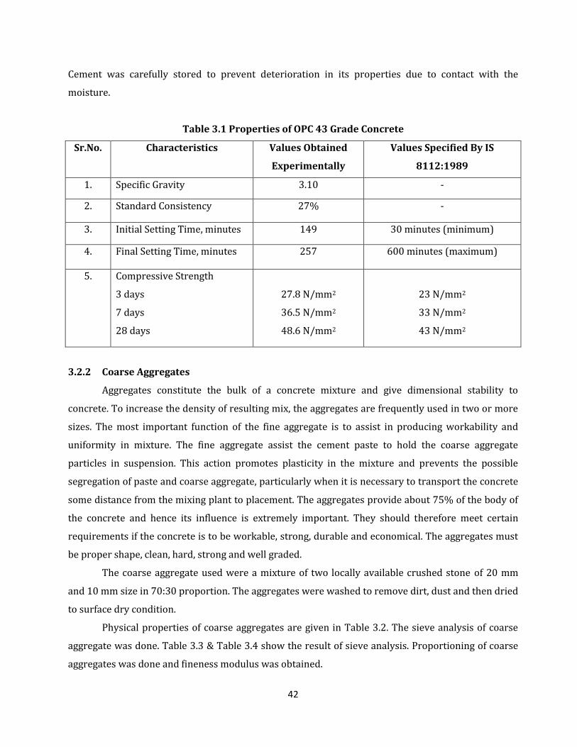
42
Cement was carefully stored to prevent deterioration in its properties due to contact with the
moisture.
Table 3.1 Properties of OPC 43 Grade Concrete
Sr.No. Characteristics Values Obtained
Experimentally
Values Specified By IS
8112:1989
1. Specific Gravity 3.10 -
2. Standard Consistency 27% -
3. Initial Setting Time, minutes 149 30 minutes (minimum)
4. Final Setting Time, minutes 257 600 minutes (maximum)
5. Compressive Strength
3 days
7 days
28 days
27.8 N/mm2
36.5 N/mm2
48.6 N/mm2
23 N/mm2
33 N/mm2
43 N/mm2
3.2.2 Coarse Aggregates
Aggregates constitute the bulk of a concrete mixture and give dimensional stability to
concrete. To increase the density of resulting mix, the aggregates are frequently used in two or more
sizes. The most important function of the fine aggregate is to assist in producing workability and
uniformity in mixture. The fine aggregate assist the cement paste to hold the coarse aggregate
particles in suspension. This action promotes plasticity in the mixture and prevents the possible
segregation of paste and coarse aggregate, particularly when it is necessary to transport the concrete
some distance from the mixing plant to placement. The aggregates provide about 75% of the body of
the concrete and hence its influence is extremely important. They should therefore meet certain
requirements if the concrete is to be workable, strong, durable and economical. The aggregates must
be proper shape, clean, hard, strong and well graded.
The coarse aggregate used were a mixture of two locally available crushed stone of 20 mm
and 10 mm size in 70:30 proportion. The aggregates were washed to remove dirt, dust and then dried
to surface dry condition.
Physical properties of coarse aggregates are given in Table 3.2. The sieve analysis of coarse
aggregate was done. Table 3.3 & Table 3.4 show the result of sieve analysis. Proportioning of coarse
aggregates was done and fineness modulus was obtained.
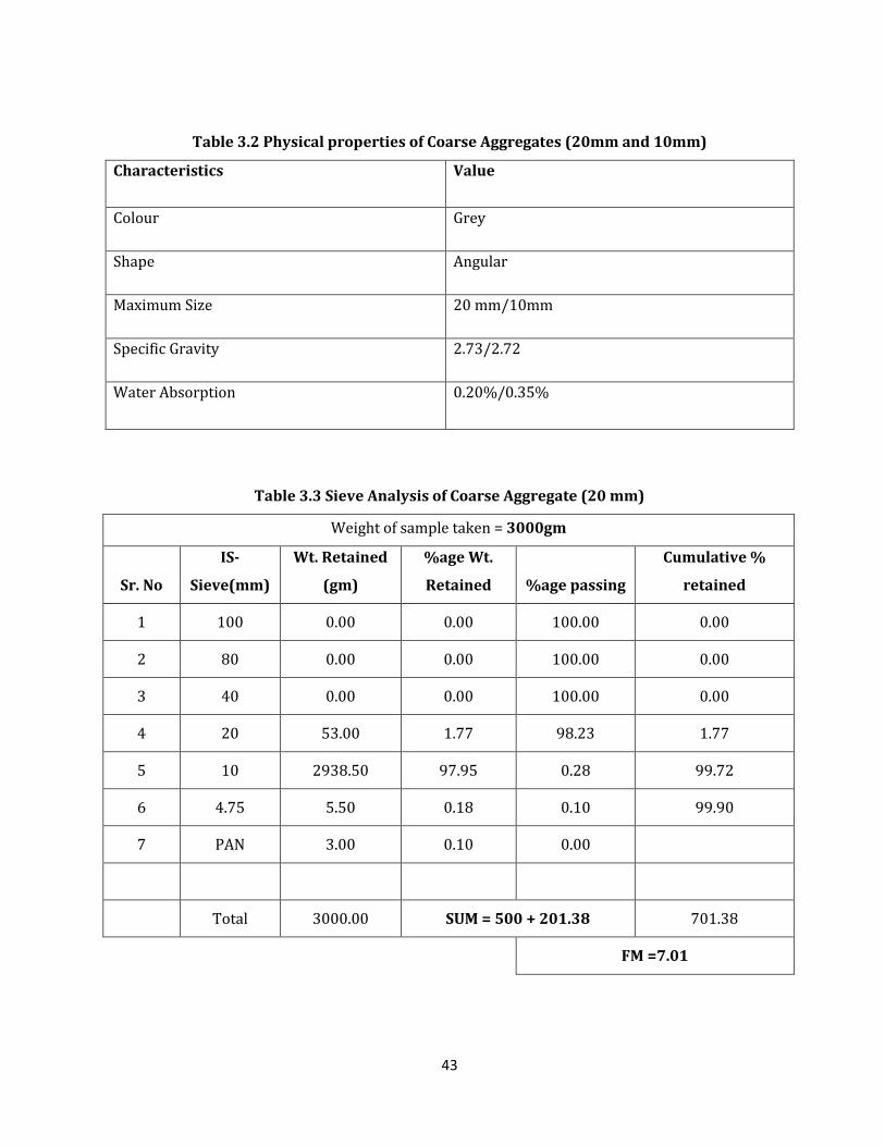
43
Table 3.2 Physical properties of Coarse Aggregates (20mm and 10mm)
Characteristics Value
Colour Grey
Shape Angular
Maximum Size 20 mm/10mm
Specific Gravity 2.73/2.72
Water Absorption 0.20%/0.35%
Table 3.3 Sieve Analysis of Coarse Aggregate (20 mm)
Weight of sample taken = 3000gm
Sr. No
IS-
Sieve(mm)
Wt. Retained
(gm)
%age Wt.
Retained %age passing
Cumulative %
retained
1 100 0.00 0.00 100.00 0.00
2 80 0.00 0.00 100.00 0.00
3 40 0.00 0.00 100.00 0.00
4 20 53.00 1.77 98.23 1.77
5 10 2938.50 97.95 0.28 99.72
6 4.75 5.50 0.18 0.10 99.90
7 PAN 3.00 0.10 0.00
Total 3000.00 SUM = 500 + 201.38 701.38
FM =7.01
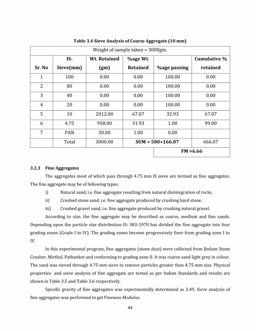
44
Table 3.4 Sieve Analysis of Coarse Aggregate (10 mm)
Weight of sample taken = 3000gm.
Sr. No
IS-
Sieve(mm)
Wt. Retained
(gm)
%age Wt.
Retained %age passing
Cumulative %
retained
1 100 0.00 0.00 100.00 0.00
2 80 0.00 0.00 100.00 0.00
3 40 0.00 0.00 100.00 0.00
4 20 0.00 0.00 100.00 0.00
5 10 2012.00 67.07 32.93 67.07
6 4.75 958.00 31.93 1.00 99.00
7 PAN 30.00 1.00 0.00
Total 3000.00 SUM = 500+166.07 666.07
FM =6.66
3.2.3 Fine Aggregates
The aggregates most of which pass through 4.75 mm IS sieve are termed as fine aggregates.
The fine aggregate may be of following types:
i) Natural sand, i.e. fine aggregate resulting from natural disintegration of rocks.
ii) Crushed stone sand, i.e. fine aggregate produced by crushing hard stone.
iii) Crushed gravel sand, i.e. fine aggregate produced by crushing natural gravel.
According to size, the fine aggregate may be described as coarse, medium and fine sands.
Depending upon the particle size distribution IS: 383-1970 has divided the fine aggregate into four
grading zones (Grade I to IV). The grading zones become progressively finer from grading zone I to
IV.
In this experimental program, fine aggregates (stone dust) were collected from Jhelum Stone
Crusher, Mirthal, Pathankot and conforming to grading zone II. It was coarse sand light grey in colour.
The sand was sieved through 4.75 mm sieve to remove particles greater than 4.75 mm size. Physical
properties and sieve analysis of fine aggregate are tested as per Indian Standards and results are
shown in Table 3.5 and Table 3.6 respectively.
Specific gravity of fine aggregates was experimentally determined as 2.49. Sieve analysis of
fine aggregates was performed to get Fineness Modulus.
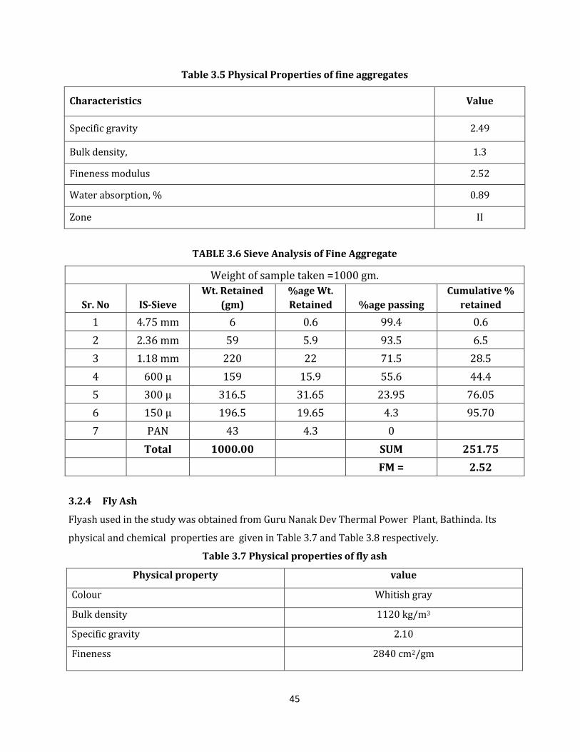
45
Table 3.5 Physical Properties of fine aggregates
Characteristics Value
Specific gravity 2.49
Bulk density, 1.3
Fineness modulus 2.52
Water absorption, % 0.89
Zone II
TABLE 3.6 Sieve Analysis of Fine Aggregate
Weight of sample taken =1000 gm.
Sr. No IS-Sieve
Wt. Retained
(gm)
%age Wt.
Retained %age passing
Cumulative %
retained
1 4.75 mm 6 0.6 99.4 0.6
2 2.36 mm 59 5.9 93.5 6.5
3 1.18 mm 220 22 71.5 28.5
4 600 μ 159 15.9 55.6 44.4
5 300 μ 316.5 31.65 23.95 76.05
6 150 μ 196.5 19.65 4.3 95.70
7 PAN 43 4.3 0
Total 1000.00
SUM 251.75
FM = 2.52
3.2.4 Fly Ash
Flyash used in the study was obtained from Guru Nanak Dev Thermal Power Plant, Bathinda. Its
physical and chemical properties are given in Table 3.7 and Table 3.8 respectively.
Table 3.7 Physical properties of fly ash
Physical property value
Colour Whitish gray
Bulk density 1120 kg/m3
Specific gravity 2.10
Fineness 2840 cm2/gm
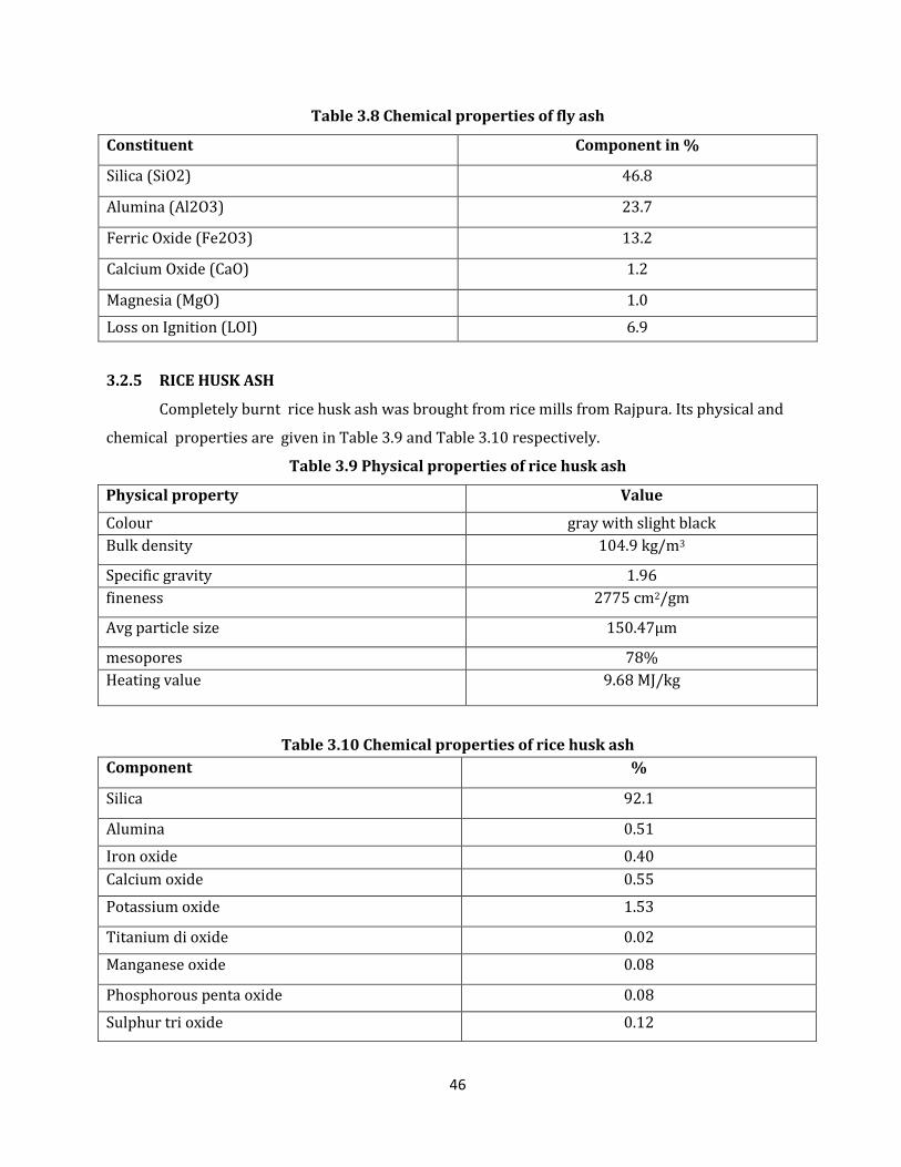
46
Table 3.8 Chemical properties of fly ash
Constituent Component in %
Silica (SiO2) 46.8
Alumina (Al2O3) 23.7
Ferric Oxide (Fe2O3) 13.2
Calcium Oxide (CaO) 1.2
Magnesia (MgO) 1.0
Loss on Ignition (LOI) 6.9
3.2.5 RICE HUSK ASH
Completely burnt rice husk ash was brought from rice mills from Rajpura. Its physical and
chemical properties are given in Table 3.9 and Table 3.10 respectively.
Table 3.9 Physical properties of rice husk ash
Physical property Value
Colour gray with slight black
Bulk density 104.9 kg/m3
Specific gravity 1.96
fineness 2775 cm2/gm
Avg particle size 150.47µm
mesopores 78%
Heating value 9.68 MJ/kg
Table 3.10 Chemical properties of rice husk ash
Component %
Silica 92.1
Alumina 0.51
Iron oxide 0.40
Calcium oxide 0.55
Potassium oxide 1.53
Titanium di oxide 0.02
Manganese oxide 0.08
Phosphorous penta oxide 0.08
Sulphur tri oxide 0.12
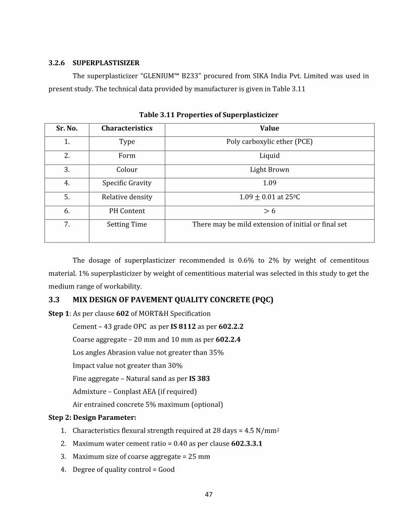
47
3.2.6 SUPERPLASTISIZER
The superplasticizer “GLENIUM™ B233” procured from SIKA India Pvt. Limited was used in
present study. The technical data provided by manufacturer is given in Table 3.11
Table 3.11 Properties of Superplasticizer
Sr. No. Characteristics Value
1. Type Poly carboxylic ether (PCE)
2. Form Liquid
3. Colour Light Brown
4. Specific Gravity 1.09
5. Relative density 1.09 0.01 at 250C
6. PH Content
7. Setting Time There may be mild extension of initial or final set
The dosage of superplasticizer recommended is 0.6% to 2% by weight of cementitous
material. 1% superplasticizer by weight of cementitious material was selected in this study to get the
medium range of workability.
3.3 MIX DESIGN OF PAVEMENT QUALITY CONCRETE (PQC)
Step 1: As per clause 602 of MORT&H Specification
Cement – 43 grade OPC as per IS 8112 as per 602.2.2
Coarse aggregate – 20 mm and 10 mm as per 602.2.4
Los angles Abrasion value not greater than 35%
Impact value not greater than 30%
Fine aggregate – Natural sand as per IS 383
Admixture – Conplast AEA (if required)
Air entrained concrete 5% maximum (optional)
Step 2: Design Parameter:
1. Characteristics flexural strength required at 28 days = 4.5 N/mm2
2. Maximum water cement ratio = 0.40 as per clause 602.3.3.1
3. Maximum size of coarse aggregate = 25 mm
4. Degree of quality control = Good
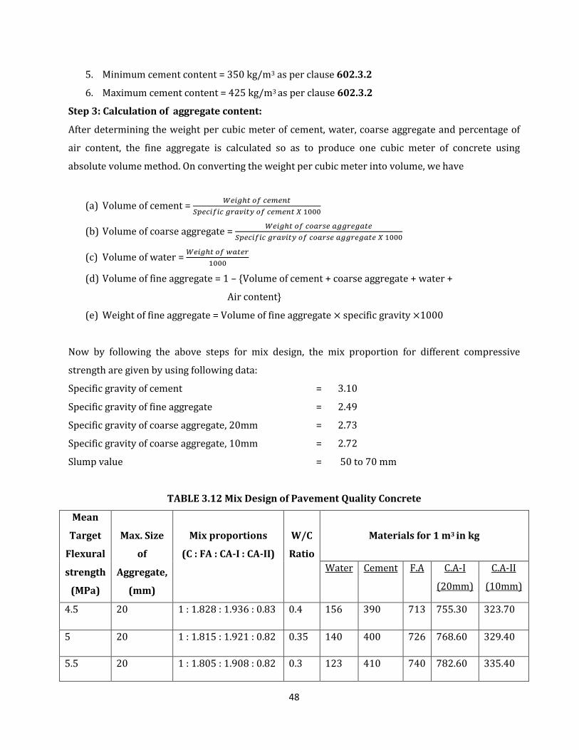
48
5. Minimum cement content = 350 kg/m3 as per clause 602.3.2
6. Maximum cement content = 425 kg/m3 as per clause 602.3.2
Step 3: Calculation of aggregate content:
After determining the weight per cubic meter of cement, water, coarse aggregate and percentage of
air content, the fine aggregate is calculated so as to produce one cubic meter of concrete using
absolute volume method. On converting the weight per cubic meter into volume, we have
(a) Volume of cement =
(b) Volume of coarse aggregate =
(c) Volume of water =
(d) Volume of fine aggregate = 1 – {Volume of cement + coarse aggregate + water +
Air content}
(e) Weight of fine aggregate = Volume of fine aggregate specific gravity 1000
Now by following the above steps for mix design, the mix proportion for different compressive
strength are given by using following data:
Specific gravity of cement = 3.10
Specific gravity of fine aggregate = 2.49
Specific gravity of coarse aggregate, 20mm = 2.73
Specific gravity of coarse aggregate, 10mm = 2.72
Slump value = 50 to 70 mm
TABLE 3.12 Mix Design of Pavement Quality Concrete
Mean
Target
Flexural
strength
(MPa)
Max. Size
of
Aggregate,
(mm)
Mix proportions
(C : FA : CA-I : CA-II)
W/C
Ratio
Materials for 1 m3 in kg
Water Cement F.A C.A-I
(20mm)
C.A-II
(10mm)
4.5 20 1 : 1.828 : 1.936 : 0.83 0.4 156 390 713 755.30 323.70
5 20 1 : 1.815 : 1.921 : 0.82 0.35 140 400 726 768.60 329.40
5.5 20 1 : 1.805 : 1.908 : 0.82 0.3 123 410 740 782.60 335.40
49
CHAPTER-4
RESULTS AND DISCUSSIONS
4.1 GENERAL
The present study was undertaken to investigate the compressive strength and flexural
strength of concrete with different levels of replacement of cement with fly ash and rice husk ash in
concrete mix. Cement was partially replaced by fly ash at three different levels of replacement i.e.
10%, 20% and 30% and same with rice husk ash. Concrete mixtures were also cast with combined
replacements of flyash and rice husk ash. Tests were performed after 7 and 28 days of curing of
concrete. Cubes and beams were prepared for determining compressive strength and flexural
strength of concrete with different water-cement ratio as 0.30, 0.35 and 0.40 for minimum required
flexural strengths of 5.5 N/mm2 5 N/mm2 4.5N/mm2, respectively. Super-plasticizer was used in all
the mixes at 1% level by weight of cementitious material.
4.2 COMPRESSIVE STRENGTH
4.2.1 General
In most structural applications, concrete is employed primarily to resist compressive stresses.
When a plain concrete member is subjected to compression, the failure of the member takes place, in
its vertical plane along the diagonal. The vertical crack occurs due to lateral tensile strains. A flow in
the concrete, which is in the form of micro crack along the vertical axis of the member will take place
on the application of axial compression load and propagate further due to the lateral tensile strains.
4.2.2 Test Procedure and Results
Test specimens of size 150mm x 150mm x 150mm were prepared for testing the compressive
strength. In this study, the mix was done manually. The cement and fine aggregate were first mixed
dry to uniform colour and then coarse aggregate was added and mixed with the mixture of cement
and fine aggregates. Water was then added and the whole mass mixed. The interior surface of the
moulds and the base plate were highly oiled before concrete was placed. After this the specimens
were removed from the moulds and placed in clean fresh water at for 28 days curing. For testing in
compression, no cushioning material was placed between the specimen and the plates of the machine.
The load was applied axially without shock till the specimen was crushed. Test results of compressive
strength test at the age of 28 days are given in the Table 4.1. Table 4.2 and Table 4.3.
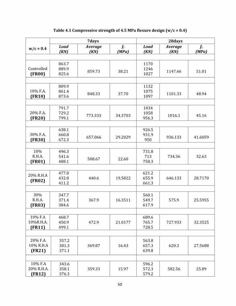
50
Table 4.1 Compressive strength of 4.5 MPa flexure design (w/c = 0.4)
w/c = 0.4
7days 28days
Load (KN)
Average (KN)
fc (MPa)
Load (KN)
Average (KN)
fc (MPa)
Controlled (FR00)
863.7 889.9 825.6
859.73
38.21
1170 1246 1027
1147.66
51.01
10% F.A. (FR10)
809.9 861.4 873.6
848.33
37.70
1132 1075 1097
1101.33
48.94
20% F.A. (FR20)
791.7 729.2 799.1
773.333
34.3703
1034 1058 956.3
1016.1
45.16
30% F.A.
(FR30)
638.1 660.8 672.3
657.066
29.2029
926.5 931.9 950
936.133
41.6059
10%
R.H.A. (FR01)
496.3 541.6 488.1
508.67
22.60
731.8 713
758.3 734.36 32.63
20% R.H.A
(FR02)
477.8 432.8 411.2
440.6 19.5822 621.2 655.9 661.3
646.133 28.7170
30%
R.H.A.
(FR03)
347.7 371.4 384.6
367.9 16.3511 560.1 549.7 617.9
575.9 25.5955
10% F.A
10%R.H.A.
(FR11)
468.7 450.9 499.1
472.9 21.0177 689.6 765.7 728.5
727.933 32.3525
20% F.A.
10% R.H.A (FR21)
357.2 381.3 371.1
369.87 16.43 563.8 657.3 639.8
620.3 27.5688
10% F.A
20% R.H.A. (FR12)
343.6 358.1 376.3
359.33 15.97 596.2 572.3 579.2
582.56 25.89
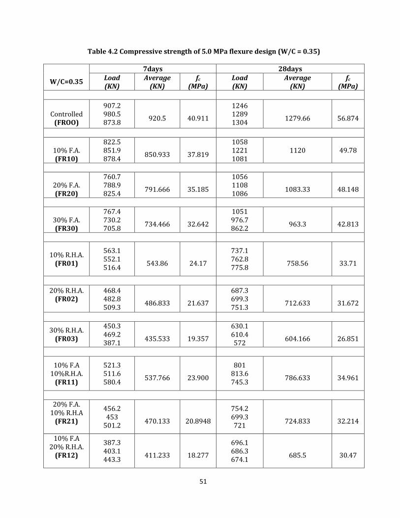
51
Table 4.2 Compressive strength of 5.0 MPa flexure design (W/C = 0.35)
W/C=0.35
7days 28days Load (KN)
Average (KN)
fc (MPa)
Load (KN)
Average (KN)
fc (MPa)
Controlled (FROO)
907.2 980.5 873.8
920.5
40.911
1246 1289 1304
1279.66
56.874
10% F.A. (FR10)
822.5 851.9 878.4
850.933
37.819
1058 1221 1081
1120 49.78
20% F.A. (FR20)
760.7 788.9 825.4
791.666
35.185
1056 1108 1086
1083.33
48.148
30% F.A. (FR30)
767.4 730.2 705.8
734.466
32.642
1051 976.7 862.2
963.3
42.813
10% R.H.A. (FR01)
563.1 552.1 516.4
543.86
24.17
737.1 762.8 775.8
758.56
33.71
20% R.H.A.
(FR02)
468.4 482.8 509.3
486.833
21.637
687.3 699.3 751.3
712.633
31.672
30% R.H.A.
(FR03)
450.3 469.2 387.1
435.533
19.357
630.1 610.4 572
604.166
26.851
10% F.A 10%R.H.A.
(FR11)
521.3 511.6 580.4
537.766
23.900
801 813.6 745.3
786.633
34.961
20% F.A.
10% R.H.A (FR21)
456.2 453
501.2
470.133
20.8948
754.2 699.3 721
724.833
32.214
10% F.A 20% R.H.A.
(FR12)
387.3 403.1 443.3
411.233
18.277
696.1 686.3 674.1
685.5
30.47
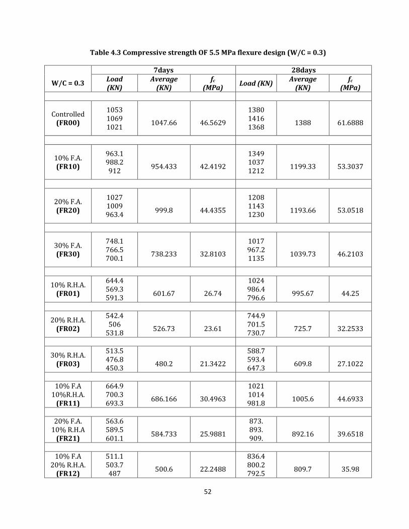
52
Table 4.3 Compressive strength OF 5.5 MPa flexure design (W/C = 0.3)
W/C = 0.3
7days 28days Load (KN)
Average (KN)
fc
(MPa) Load (KN)
Average (KN)
fc (MPa)
Controlled
(FR00)
1053 1069 1021
1047.66
46.5629
1380 1416 1368
1388
61.6888
10% F.A. (FR10)
963.1 988.2 912
954.433
42.4192
1349 1037 1212
1199.33
53.3037
20% F.A. (FR20)
1027 1009 963.4
999.8
44.4355
1208 1143 1230
1193.66
53.0518
30% F.A. (FR30)
748.1 766.5 700.1
738.233
32.8103
1017 967.2 1135
1039.73
46.2103
10% R.H.A. (FR01)
644.4 569.3 591.3
601.67
26.74
1024 986.4 796.6
995.67
44.25
20% R.H.A. (FR02)
542.4 506
531.8
526.73
23.61
744.9 701.5 730.7
725.7
32.2533
30% R.H.A. (FR03)
513.5 476.8 450.3
480.2
21.3422
588.7 593.4 647.3
609.8
27.1022
10% F.A 10%R.H.A.
(FR11)
664.9 700.3 693.3
686.166
30.4963
1021 1014 981.8
1005.6
44.6933
20% F.A. 10% R.H.A
(FR21)
563.6 589.5 601.1
584.733
25.9881
873. 893. 909.
892.16
39.6518
10% F.A 20% R.H.A.
(FR12)
511.1 503.7 487
500.6
22.2488
836.4 800.2 792.5
809.7
35.98
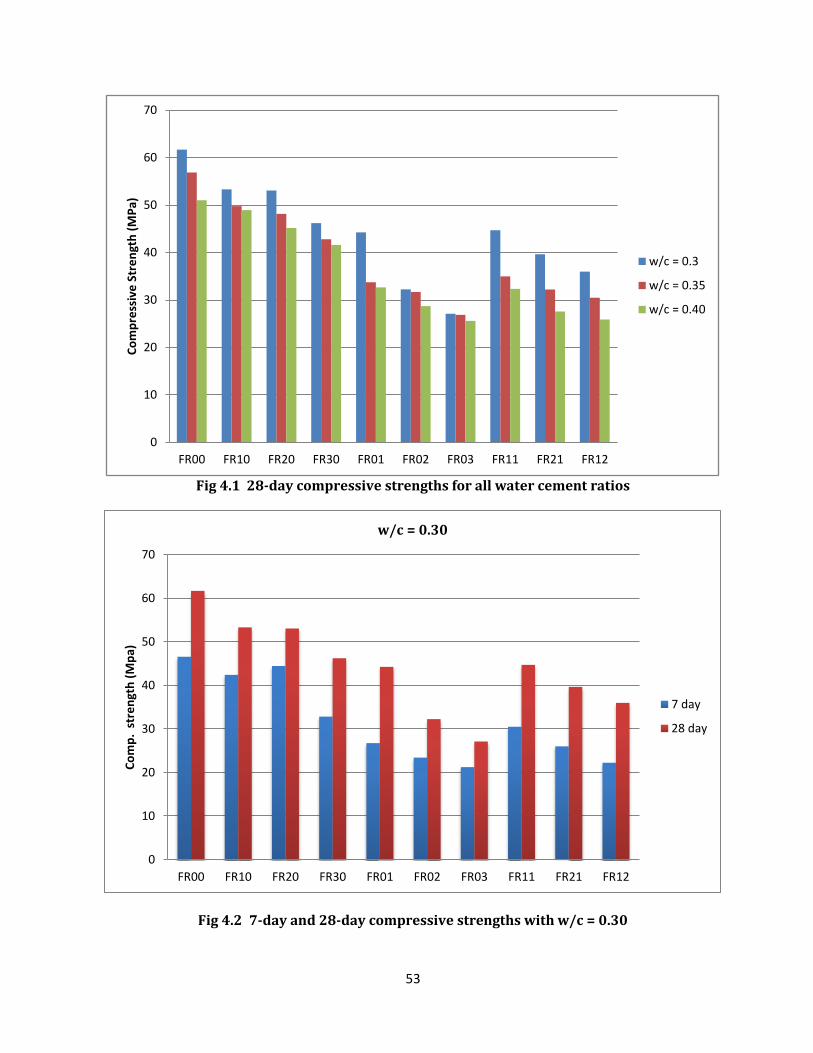
53
Fig 4.1 28-day compressive strengths for all water cement ratios
Fig 4.2 7-day and 28-day compressive strengths with w/c = 0.30
0
10
20
30
40
50
60
70
FR00 FR10 FR20 FR30 FR01 FR02 FR03 FR11 FR21 FR12
Co
mp
ress
ive
Str
en
gth
(M
Pa)
w/c = 0.3
w/c = 0.35
w/c = 0.40
0
10
20
30
40
50
60
70
FR00 FR10 FR20 FR30 FR01 FR02 FR03 FR11 FR21 FR12
Co
mp
. st
ren
gth
(M
pa)
w/c = 0.30
7 day
28 day
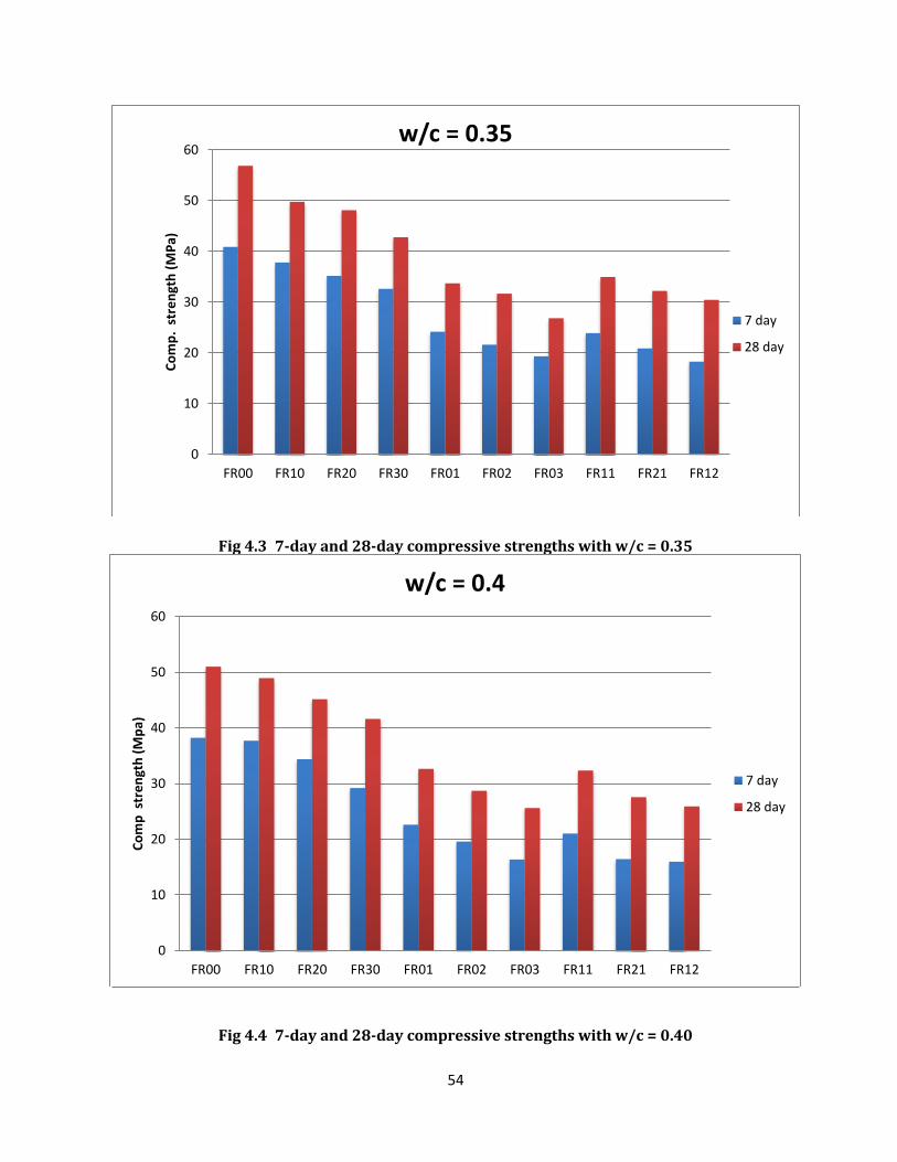
54
Fig 4.3 7-day and 28-day compressive strengths with w/c = 0.35
Fig 4.4 7-day and 28-day compressive strengths with w/c = 0.40
0
10
20
30
40
50
60
FR00 FR10 FR20 FR30 FR01 FR02 FR03 FR11 FR21 FR12
Co
mp
. st
ren
gth
(M
Pa)
w/c = 0.35
7 day
28 day
0
10
20
30
40
50
60
FR00 FR10 FR20 FR30 FR01 FR02 FR03 FR11 FR21 FR12
Co
mp
str
en
gth
(M
pa)
w/c = 0.4
7 day
28 day
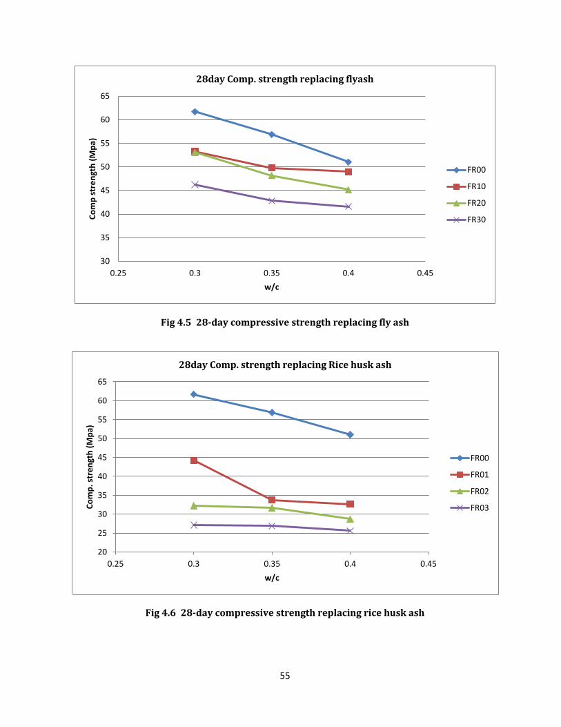
55
Fig 4.5 28-day compressive strength replacing fly ash
Fig 4.6 28-day compressive strength replacing rice husk ash
30
35
40
45
50
55
60
65
0.25 0.3 0.35 0.4 0.45
Co
mp
str
en
gth
(M
pa)
w/c
28day Comp. strength replacing flyash
FR00
FR10
FR20
FR30
20
25
30
35
40
45
50
55
60
65
0.25 0.3 0.35 0.4 0.45
Co
mp
. str
en
gth
(M
pa)
w/c
28day Comp. strength replacing Rice husk ash
FR00
FR01
FR02
FR03
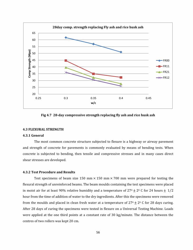
56
Fig 4.7 28-day compressive strength replacing fly ash and rice husk ash
4.3 FLEXURAL STRENGTH
4.3.1 General
The most common concrete structure subjected to flexure is a highway or airway pavement
and strength of concrete for pavements is commonly evaluated by means of bending tests. When
concrete is subjected to bending, then tensile and compressive stresses and in many cases direct
shear stresses are developed.
4.3.2 Test Procedure and Results
Test specimens of beam size 150 mm 150 mm 700 mm were prepared for testing the
flexural strength of unreinforced beams. The beam moulds containing the test specimens were placed
in moist air for at least 90% relative humidity and a temperature of 270 20 C for 24 hours ⁄
hour from the time of addition of water to the dry ingredients. After this the specimens were removed
from the moulds and placed in clean fresh water at a temperature of 270 20 C for 28 days curing.
After 28 days of curing the specimens were tested in flexure on a Universal Testing Machine. Loads
were applied at the one third points at a constant rate of 30 kg/minute. The distance between the
centres of two rollers was kept 20 cm.
20
25
30
35
40
45
50
55
60
65
0.25 0.3 0.35 0.4 0.45
Co
mp
Str
en
gth
(M
pa)
w/c
28day comp. strength replacing Fly ash and rice husk ash
FR00
FR11
FR21
FR12
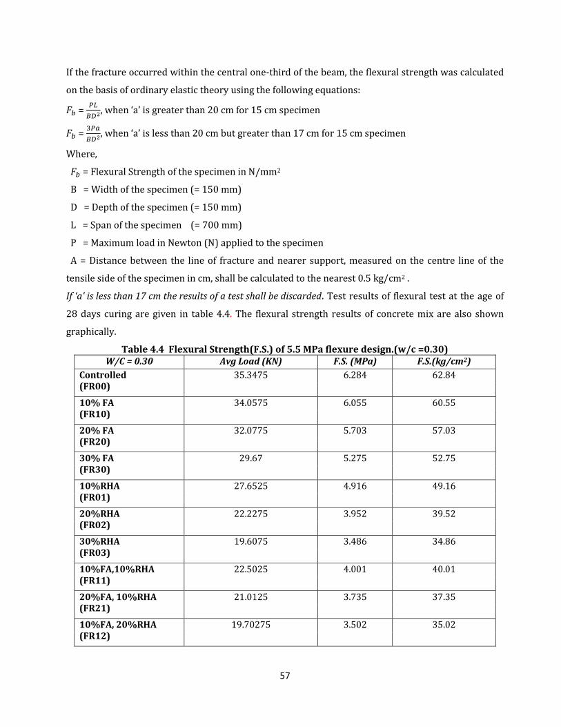
57
If the fracture occurred within the central one-third of the beam, the flexural strength was calculated
on the basis of ordinary elastic theory using the following equations:
=
, when ‘a’ is greater than 20 cm for 15 cm specimen
=
, when ‘a’ is less than 20 cm but greater than 17 cm for 15 cm specimen
Where,
= Flexural Strength of the specimen in N/mm2
B = Width of the specimen (= 150 mm)
D = Depth of the specimen (= 150 mm)
L = Span of the specimen (= 700 mm)
P = Maximum load in Newton (N) applied to the specimen
A = Distance between the line of fracture and nearer support, measured on the centre line of the
tensile side of the specimen in cm, shall be calculated to the nearest 0.5 kg/cm2 .
If ‘a’ is less than 17 cm the results of a test shall be discarded. Test results of flexural test at the age of
28 days curing are given in table 4.4. The flexural strength results of concrete mix are also shown
graphically.
Table 4.4 Flexural Strength(F.S.) of 5.5 MPa flexure design.(w/c =0.30) W/C = 0.30 Avg Load (KN) F.S. (MPa) F.S.(kg/cm2)
Controlled (FR00)
35.3475 6.284 62.84
10% FA (FR10)
34.0575 6.055 60.55
20% FA (FR20)
32.0775 5.703 57.03
30% FA (FR30)
29.67 5.275 52.75
10%RHA (FR01)
27.6525 4.916 49.16
20%RHA (FR02)
22.2275 3.952 39.52
30%RHA (FR03)
19.6075 3.486 34.86
10%FA,10%RHA (FR11)
22.5025 4.001 40.01
20%FA, 10%RHA (FR21)
21.0125 3.735 37.35
10%FA, 20%RHA (FR12)
19.70275 3.502 35.02
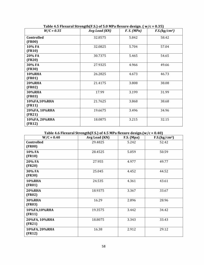
58
Table 4.5 Flexural Strength(F.S.) of 5.0 MPa flexure design. ( w/c = 0.35) W/C = 0.35 Avg Load (KN) F. S. (MPa) F.S.(kg/cm2)
Controlled (FR00)
32.8575 5.842 58.42
10% FA (FR10)
32.0825 5.704 57.04
20% FA (FR20)
30.7375 5.465 54.65
30% FA (FR30)
27.9325 4.966 49.66
10%RHA (FR01)
26.2825 4.673 46.73
20%RHA (FR02)
21.4175 3.808 38.08
30%RHA (FR03)
17.99 3.199 31.99
10%FA,10%RHA (FR11)
21.7625 3.868 38.68
20%FA, 10%RHA (FR21)
19.6675 3.496 34.96
10%FA, 20%RHA (FR12)
18.0875 3.215 32.15
Table 4.6 Flexural Strength(F.S.) of 4.5 MPa flexure design.(w/c = 0.40)
W/C = 0.40 Avg Load (KN) F.S. (Mpa) F.S.(kg/cm2)
Controlled (FR00)
29.4825 5.242 52.42
10% FA (FR10)
28.4525 5.059 50.59
20% FA (FR20)
27.955 4.977 49.77
30% FA (FR30)
25.045 4.452 44.52
10%RHA (FR01)
24.535 4.361 43.61
20%RHA (FR02)
18.9375 3.367 33.67
30%RHA (FR03)
16.29 2.896 28.96
10%FA,10%RHA (FR11)
19.3575 3.442 34.42
20%FA, 10%RHA (FR21)
18.8075 3.343 33.43
10%FA, 20%RHA (FR12)
16.38 2.912 29.12
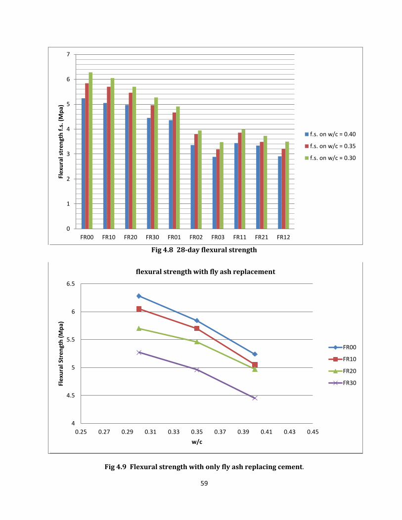
59
Fig 4.8 28-day flexural strength
Fig 4.9 Flexural strength with only fly ash replacing cement.
0
1
2
3
4
5
6
7
FR00 FR10 FR20 FR30 FR01 FR02 FR03 FR11 FR21 FR12
Fle
xura
l str
en
gth
f.s
. (M
pa)
f.s. on w/c = 0.40
f.s. on w/c = 0.35
f.s. on w/c = 0.30
4
4.5
5
5.5
6
6.5
0.25 0.27 0.29 0.31 0.33 0.35 0.37 0.39 0.41 0.43 0.45
Fle
xura
l Str
en
gth
(M
pa)
w/c
flexural strength with fly ash replacement
FR00
FR10
FR20
FR30

60
Fig 4.10 Flexural strength with rice husk ash replacing cement
Fig 4.11 Flexural strength with cement replaced by fly ash and rice husk ash both
2
2.5
3
3.5
4
4.5
5
5.5
6
6.5
0.25 0.3 0.35 0.4 0.45
Fle
xura
l Str
en
gth
(M
pa)
w/c
Flexural strength replacing Rice husk ash
FR00
FR01
FR02
FR03
2
2.5
3
3.5
4
4.5
5
5.5
6
6.5
0.25 0.3 0.35 0.4 0.45
Fle
xura
l str
en
gth
(M
pa)
w/c
Flexural strength with fly ash and rice husk ash replacement
FR00
FR11
FR21
FR12
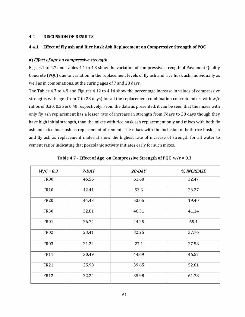
61
4.4 DISCUSSION OF RESULTS 4.4.1 Effect of Fly ash and Rice husk Ash Replacement on Compressive Strength of PQC
a) Effect of age on compressive strength
Figs. 4.1 to 4.7 and Tables 4.1 to 4.3 show the variation of compressive strength of Pavement Quality
Concrete (PQC) due to variation in the replacement levels of fly ash and rice husk ash, individually as
well as in combinations, at the curing ages of 7 and 28 days.
The Tables 4.7 to 4.9 and Figures 4.12 to 4.14 show the percentage increase in values of compressive
strengths with age (from 7 to 28 days) for all the replacement combination concrete mixes with w/c
ratios of 0.30, 0.35 & 0.40 respectively. From the data as presented, it can be seen that the mixes with
only fly ash replacement has a lesser rate of increase in strength from 7days to 28 days though they
have high initial strength, than the mixes with rice husk ash replacement only and mixes with both fly
ash and rice husk ash as replacement of cement. The mixes with the inclusion of both rice husk ash
and fly ash as replacement material show the highest rate of increase of strength for all water to
cement ratios indicating that pozzolanic activity initiates early for such mixes.
Table 4.7 - Effect of Age on Compressive Strength of PQC w/c = 0.3
W/C = 0.3 7-DAY 28-DAY % INCREASE
FR00 46.56 61.68 32.47
FR10 42.41 53.3 26.27
FR20 44.43 53.05 19.40
FR30 32.81 46.31 41.14
FR01 26.74 44.25 65.4
FR02 23.41 32.25 37.76
FR03 21.24 27.1 27.58
FR11 30.49 44.69 46.57
FR21 25.98 39.65 52.61
FR12 22.24 35.98 61.78
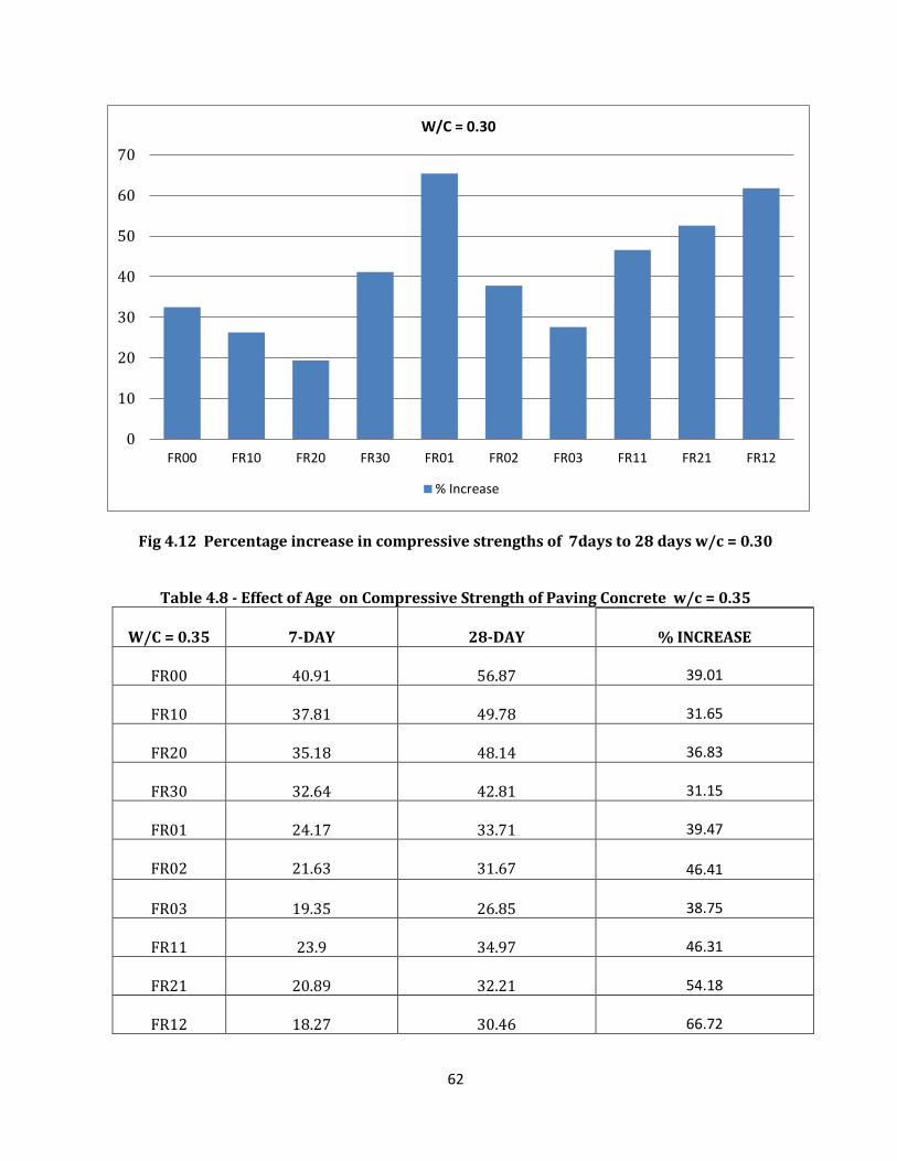
62
Fig 4.12 Percentage increase in compressive strengths of 7days to 28 days w/c = 0.30
Table 4.8 - Effect of Age on Compressive Strength of Paving Concrete w/c = 0.35
W/C = 0.35
7-DAY
28-DAY
% INCREASE
FR00
40.91
56.87 39.01
FR10
37.81
49.78 31.65
FR20
35.18
48.14 36.83
FR30
32.64
42.81 31.15
FR01
24.17
33.71 39.47
FR02
21.63
31.67 46.41
FR03
19.35
26.85 38.75
FR11
23.9
34.97 46.31
FR21
20.89
32.21 54.18
FR12
18.27
30.46 66.72
0
10
20
30
40
50
60
70
FR00 FR10 FR20 FR30 FR01 FR02 FR03 FR11 FR21 FR12
W/C = 0.30
% Increase
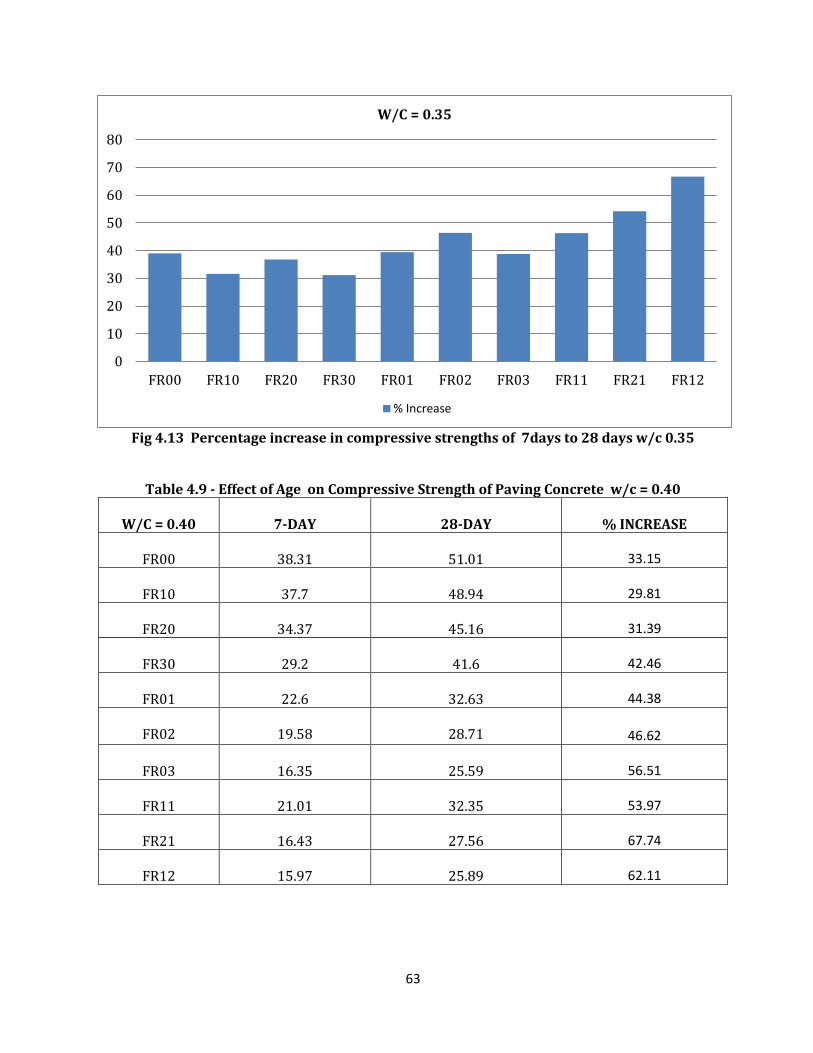
63
Fig 4.13 Percentage increase in compressive strengths of 7days to 28 days w/c 0.35
Table 4.9 - Effect of Age on Compressive Strength of Paving Concrete w/c = 0.40
W/C = 0.40
7-DAY
28-DAY
% INCREASE
FR00
38.31
51.01 33.15
FR10
37.7
48.94 29.81
FR20
34.37
45.16 31.39
FR30
29.2
41.6 42.46
FR01
22.6
32.63 44.38
FR02
19.58
28.71 46.62
FR03
16.35
25.59 56.51
FR11
21.01
32.35 53.97
FR21
16.43
27.56 67.74
FR12
15.97
25.89 62.11
0
10
20
30
40
50
60
70
80
FR00 FR10 FR20 FR30 FR01 FR02 FR03 FR11 FR21 FR12
W/C = 0.35
% Increase
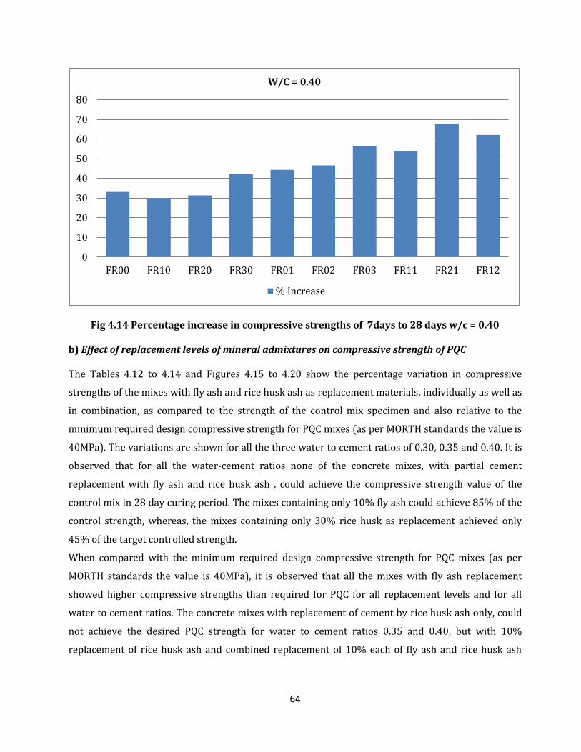
64
Fig 4.14 Percentage increase in compressive strengths of 7days to 28 days w/c = 0.40 b) Effect of replacement levels of mineral admixtures on compressive strength of PQC The Tables 4.12 to 4.14 and Figures 4.15 to 4.20 show the percentage variation in compressive
strengths of the mixes with fly ash and rice husk ash as replacement materials, individually as well as
in combination, as compared to the strength of the control mix specimen and also relative to the
minimum required design compressive strength for PQC mixes (as per MORTH standards the value is
40MPa). The variations are shown for all the three water to cement ratios of 0.30, 0.35 and 0.40. It is
observed that for all the water-cement ratios none of the concrete mixes, with partial cement
replacement with fly ash and rice husk ash , could achieve the compressive strength value of the
control mix in 28 day curing period. The mixes containing only 10% fly ash could achieve 85% of the
control strength, whereas, the mixes containing only 30% rice husk as replacement achieved only
45% of the target controlled strength.
When compared with the minimum required design compressive strength for PQC mixes (as per
MORTH standards the value is 40MPa), it is observed that all the mixes with fly ash replacement
showed higher compressive strengths than required for PQC for all replacement levels and for all
water to cement ratios. The concrete mixes with replacement of cement by rice husk ash only, could
not achieve the desired PQC strength for water to cement ratios 0.35 and 0.40, but with 10%
replacement of rice husk ash and combined replacement of 10% each of fly ash and rice husk ash
0
10
20
30
40
50
60
70
80
FR00 FR10 FR20 FR30 FR01 FR02 FR03 FR11 FR21 FR12
W/C = 0.40
% Increase
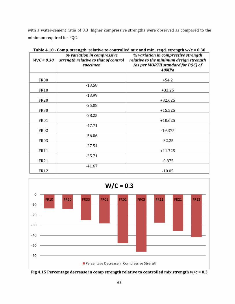
65
with a water-cement ratio of 0.3 higher compressive strengths were observed as compared to the
minimum required for PQC.
Table 4.10 - Comp. strength relative to controlled mix and min. reqd. strength w/c = 0.30
W/C = 0.30
% variation in compressive strength relative to that of control
specimen
% variation in compressive strength relative to the minimum design strength
(as per MORTH standard for PQC) of 40MPa
FR00
+54.2
FR10
-13.58 +33.25
FR20
-13.99 +32.625
FR30
-25.08 +15.525
FR01
-28.25 +10.625
FR02
-47.71 -19.375
FR03
-56.06 -32.25
FR11
-27.54 +11.725
FR21
-35.71 -0.875
FR12
-41.67 -10.05
Fig 4.15 Percentage decrease in comp strength relative to controlled mix strength w/c = 0.3
-60
-50
-40
-30
-20
-10
0
FR10 FR20 FR30 FR01 FR02 FR03 FR11 FR21 FR12
W/C = 0.3
Percentage Decrease in Compressive Strength

66
Fig 4.16 Percentage of compressive strengths relative to reqd. min. strength at w/c =0.30
Table 4.11 Comp. strength relative to controlled mix and reqd. min. strengths at w/c = 0.35
W/C = 0.35 % variation in compressive
strength relative to that of control specimen
% variation in compressive strength relative to the minimum design
strength (as per MORTH standard for PQC) of 40MPa
FR10
-12.46 +24.45
FR20
-15.35 +20.35
FR30
-24.72
+7.025
FR01
-40.72 -15.725
FR02
-44.31 -20.825
FR03
-52.78 -32.875
FR11
-38.50 -12.575
FR21
-43.36 -19.475
FR12
-46.43 -23.85
-40
-30
-20
-10
0
10
20
30
40
50
60
FR00 FR10 FR20 FR30 FR01 FR02 FR03 FR11 FR21 FR12
w/c = 0.30
% increase from min. reqd. strength % decrease from min. reqd. strength
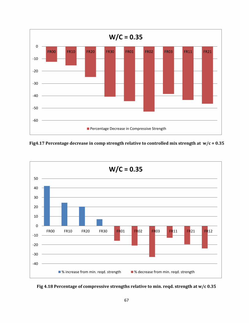
67
Fig4.17 Percentage decrease in comp strength relative to controlled mix strength at w/c = 0.35
Fig 4.18 Percentage of compressive strengths relative to min. reqd. strength at w/c 0.35
-60
-50
-40
-30
-20
-10
0
FR00 FR10 FR20 FR30 FR01 FR02 FR03 FR11 FR21
W/C = 0.35
Percentage Decrease in Compressive Strength
-40
-30
-20
-10
0
10
20
30
40
50
FR00 FR10 FR20 FR30 FR01 FR02 FR03 FR11 FR21 FR12
W/C = 0.35
% increase from min. reqd. strength % decrease from min. reqd. strength
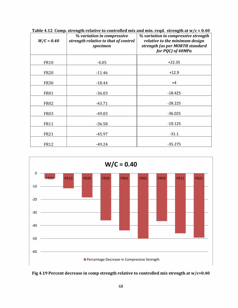
68
Table 4.12 Comp. strength relative to controlled mix and min. reqd. strength at w/c = 0.40
W/C = 0.40 % variation in compressive
strength relative to that of control specimen
% variation in compressive strength relative to the minimum design
strength (as per MORTH standard for PQC) of 40MPa
FR10
-4.05 +22.35
FR20
-11.46 +12.9
FR30
-18.44 +4
FR01
-36.03 -18.425
FR02
-43.71 -28.225
FR03
-49.83 -36.025
FR11
-36.58 -19.125
FR21
-45.97 -31.1
FR12
-49.24 -35.275
Fig 4.19 Percent decrease in comp strength relative to controlled mix strength at w/c=0.40
-60
-50
-40
-30
-20
-10
0
FR00 FR10 FR20 FR30 FR01 FR02 FR03 FR11 FR21
W/C = 0.40
Percentage Decrease in Compressive Strength
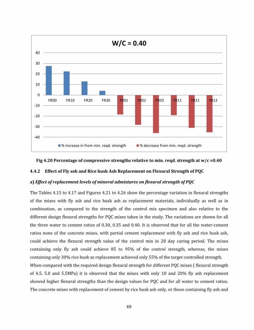
69
Fig 4.20 Percentage of compressive strengths relative to min. reqd. strength at w/c =0.40 4.4.2 Effect of Fly ash and Rice husk Ash Replacement on Flexural Strength of PQC a) Effect of replacement levels of mineral admixtures on flexural strength of PQC The Tables 4.15 to 4.17 and Figures 4.21 to 4.26 show the percentage variation in flexural strengths
of the mixes with fly ash and rice husk ash as replacement materials, individually as well as in
combination, as compared to the strength of the control mix specimen and also relative to the
different design flexural strengths for PQC mixes taken in the study. The variations are shown for all
the three water to cement ratios of 0.30, 0.35 and 0.40. It is observed that for all the water-cement
ratios none of the concrete mixes, with partial cement replacement with fly ash and rice husk ash,
could achieve the flexural strength value of the control mix in 28 day curing period. The mixes
containing only fly ash could achieve 85 to 95% of the control strength, whereas, the mixes
containing only 30% rice husk as replacement achieved only 55% of the target controlled strength.
When compared with the required design flexural strength for different PQC mixes ( flexural strength
of 4.5, 5.0 and 5.5MPa) it is observed that the mixes with only 10 and 20% fly ash replacement
showed higher flexural strengths than the design values for PQC and for all water to cement ratios.
The concrete mixes with replacement of cement by rice husk ash only, or those containing fly ash and
-40
-30
-20
-10
0
10
20
30
40
FR00 FR10 FR20 FR30 FR01 FR02 FR03 FR11 FR21 FR12
W/C = 0.40
% increase in from min. reqd. strength % decrease from min. reqd. strength
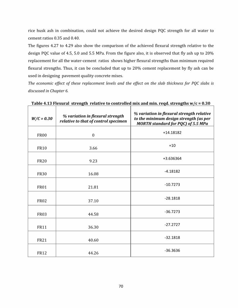
70
rice husk ash in combination, could not achieve the desired design PQC strength for all water to
cement ratios 0.35 and 0.40.
The figures 4.27 to 4.29 also show the comparison of the achieved flexural strength relative to the
design PQC value of 4.5, 5.0 and 5.5 MPa. From the figure also, it is observed that fly ash up to 20%
replacement for all the water-cement ratios shows higher flexural strengths than minimum required
flexural strengths. Thus, it can be concluded that up to 20% cement replacement by fly ash can be
used in designing pavement quality concrete mixes.
The economic effect of these replacement levels and the effect on the slab thickness for PQC slabs is
discussed in Chapter 6.
Table 4.13 Flexural strength relative to controlled mix and min. reqd. strengths w/c = 0.30
W/C = 0.30
% variation in flexural strength
relative to that of control specimen
% variation in flexural strength relative to the minimum design strength (as per
MORTH standard for PQC) of 5.5 MPa
FR00
0
+14.18182
FR10
3.66
+10
FR20
9.23
+3.636364
FR30
16.08
-4.18182
FR01
21.81
-10.7273
FR02
37.10
-28.1818
FR03
44.58
-36.7273
FR11
36.30
-27.2727
FR21
40.60
-32.1818
FR12
44.26
-36.3636
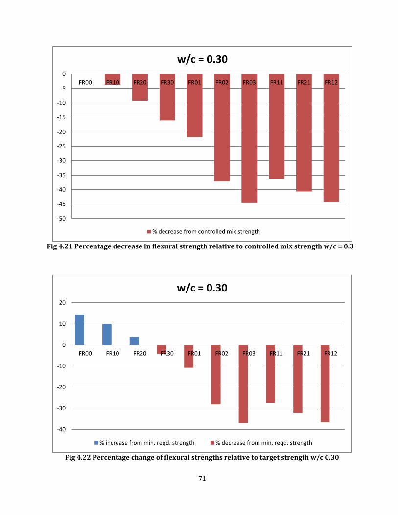
71
Fig 4.21 Percentage decrease in flexural strength relative to controlled mix strength w/c = 0.3
Fig 4.22 Percentage change of flexural strengths relative to target strength w/c 0.30
-50
-45
-40
-35
-30
-25
-20
-15
-10
-5
0
FR00 FR10 FR20 FR30 FR01 FR02 FR03 FR11 FR21 FR12
w/c = 0.30
% decrease from controlled mix strength
-40
-30
-20
-10
0
10
20
FR00 FR10 FR20 FR30 FR01 FR02 FR03 FR11 FR21 FR12
w/c = 0.30
% increase from min. reqd. strength % decrease from min. reqd. strength
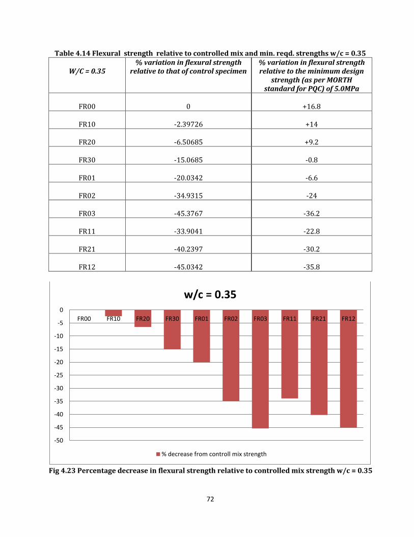
72
Table 4.14 Flexural strength relative to controlled mix and min. reqd. strengths w/c = 0.35
W/C = 0.35 % variation in flexural strength
relative to that of control specimen % variation in flexural strength relative to the minimum design
strength (as per MORTH standard for PQC) of 5.0MPa
FR00 0 +16.8
FR10 -2.39726 +14
FR20 -6.50685 +9.2
FR30 -15.0685 -0.8
FR01 -20.0342 -6.6
FR02 -34.9315 -24
FR03 -45.3767 -36.2
FR11 -33.9041 -22.8
FR21 -40.2397 -30.2
FR12 -45.0342 -35.8
Fig 4.23 Percentage decrease in flexural strength relative to controlled mix strength w/c = 0.35
-50
-45
-40
-35
-30
-25
-20
-15
-10
-5
0
FR00 FR10 FR20 FR30 FR01 FR02 FR03 FR11 FR21 FR12
w/c = 0.35
% decrease from controll mix strength
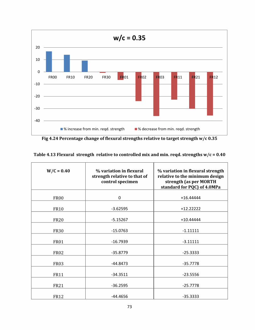
73
Fig 4.24 Percentage change of flexural strengths relative to target strength w/c 0.35
Table 4.13 Flexural strength relative to controlled mix and min. reqd. strengths w/c = 0.40
W/C = 0.40
% variation in flexural
strength relative to that of control specimen
% variation in flexural strength relative to the minimum design
strength (as per MORTH standard for PQC) of 4.0MPa
FR00 0 +16.44444
FR10 -3.62595 +12.22222
FR20 -5.15267 +10.44444
FR30 -15.0763 -1.11111
FR01 -16.7939 -3.11111
FR02 -35.8779 -25.3333
FR03 -44.8473 -35.7778
FR11 -34.3511 -23.5556
FR21 -36.2595 -25.7778
FR12 -44.4656 -35.3333
-40
-30
-20
-10
0
10
20
FR00 FR10 FR20 FR30 FR01 FR02 FR03 FR11 FR21 FR12
w/c = 0.35
% increase from min. reqd. strength % decrease from min. reqd. strength
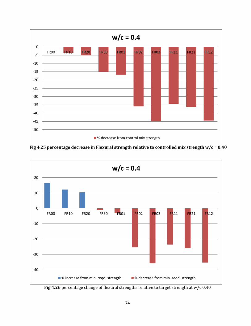
74
Fig 4.25 percentage decrease in Flexural strength relative to controlled mix strength w/c = 0.40
Fig 4.26 percentage change of flexural strengths relative to target strength at w/c 0.40
-50
-45
-40
-35
-30
-25
-20
-15
-10
-5
0
FR00 FR10 FR20 FR30 FR01 FR02 FR03 FR11 FR21 FR12
w/c = 0.4
% decrease from control mix strength
-40
-30
-20
-10
0
10
20
FR00 FR10 FR20 FR30 FR01 FR02 FR03 FR11 FR21 FR12
w/c = 0.4
% increase from min. reqd. strength % decrease from min. reqd. strength
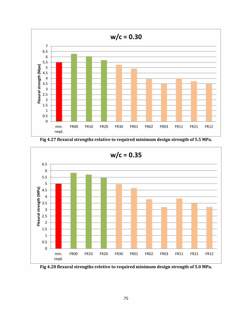
75
Fig 4.27 flexural strengths relative to required minimum design strength of 5.5 MPa.
Fig 4.28 flexural strengths reletive to required minimum design strength of 5.0 MPa.
0
0.5
1
1.5
2
2.5
3
3.5
4
4.5
5
5.5
6
6.5
7
min.reqd.
FR00 FR10 FR20 FR30 FR01 FR02 FR03 FR11 FR21 FR12
Fle
xura
l str
en
gth
(M
pa)
w/c = 0.30
0
0.5
1
1.5
2
2.5
3
3.5
4
4.5
5
5.5
6
6.5
min.reqd.
FR00 FR10 FR20 FR30 FR01 FR02 FR03 FR11 FR21 FR12
Fle
xura
l str
en
gth
(M
Pa)
w/c = 0.35
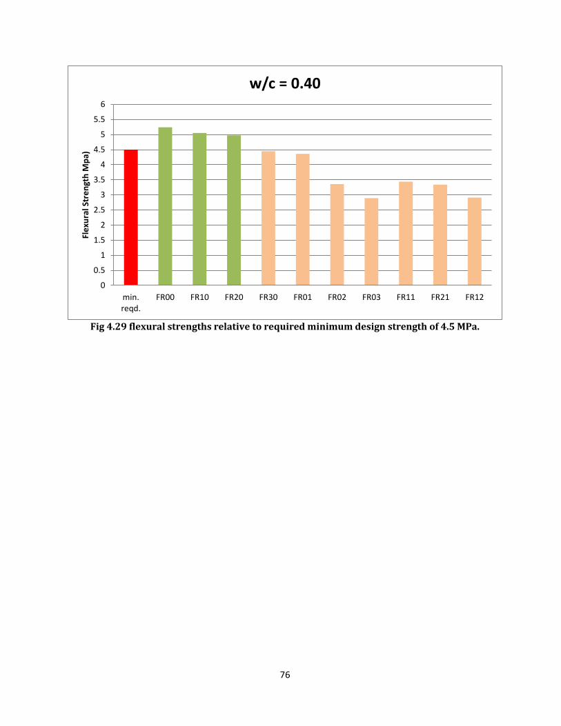
76
Fig 4.29 flexural strengths relative to required minimum design strength of 4.5 MPa.
0
0.5
1
1.5
2
2.5
3
3.5
4
4.5
5
5.5
6
min.reqd.
FR00 FR10 FR20 FR30 FR01 FR02 FR03 FR11 FR21 FR12
Fle
xura
l Str
en
gth
Mp
a)
w/c = 0.40
77
CHAPTER 5
DESIGN AND ANALYSIS OF PAVEMENT QUALITY CONCRETE SLAB
5.1 DESIGN OF PAVEMENT QUALITY CONCRETE (PQC) FOR INDIAN HIGHWAYS
5.1.1 Introduction
Guidelines for the design of rigid pavements for highways were first approved by the Cement
Concrete Road Surfacing Committee in March 1973 and published subsequently in the IRC: 58-2002
editions. In view of the recent upward revision of the legal limit on the maximum laden axle loads of
commercial vehicle from 8160 kg to 10200 kg, appropriate modifications have become necessary in
some sections of the Guidelines of IRC:58-1988, which resulted in the publication of IRC:58-2002,
“Guidelines for the Design of Plain Jointed Rigid Pavements for Highways”. The early approach to the
Design of Rigid Pavement was based on Westergaard`s analysis. Recent advance in knowledge have
led to vast changes in the design methodology.
5.1.2 Factor Governing Design
a) Factor Governing Design: It considers single and tandem axle loads, their repetition, tyre
pressure and lateral placement characteristics of commercial vehicles.
b) Wheel Load: The legal axle load limits in India have been fixed as 10.2, 19 and 24 tonnes for single
axles, tandem axles and tridem axles respectively, a large number of axles operating on National
Highways carry much higher loads than the legal limits. Data on axle load distribution of the
commercial vehicles is required to compute the number of repetitions of single and tandem axles of
different weights expected during the design period. For most of the commercial highways vehicles,
the tyre pressure ranges from 0.7 to 1.0 MPa but it is found that stresses in concrete pavements
having thickness of 20 cm or more are not affected significantly by the variation of tyre pressure in
the range mentioned earlier. A tyre pressure of 0.8 MPa may be adopted for design.
For computation of stresses in the pavements, the magnitude of axle loads should be multiplied by
Load Safety Factor (LSF). For important roads, like, Expressways, National Highways and other roads
where there will be uninterrupted traffic flow and high volume of truck traffic, the value of LSF is
taken as 1.2. For roads of lesser importance having lower proportion of truck traffic, LSF may be
taken as 1.1. For residential and other streets that carry small number of commercial traffic, the LSF
may be taken as 1.0.
c) Design Period: Normally, cement concrete pavements have a life span of 30 years and should be
designed for this period. When the traffic intensity cannot be predicted accurately for a long period of
time, and for low volume roads, a design period of twenty years may be considered. However, the
78
design engineer should use his judgement about the design life taking into consideration the factors,
like, traffic volume, the traffic growth rate, the capacity of the road.
d) Design Traffic: Assessment of average traffic should normally be based on 7 24 hours count
made in accordance with IRC: 9 “Traffic Census on Non-Urban Roads”. The actual value of growth rate
‘r’ of heavy commercial vehicles should be determined. However, if actual data is not available, an
average annual growth rate of 7.5 percent may be adopted.
The cumulative number of repetitions of axles during the design period may be adopted from the
following formula:
C =
Where
C = Cumulative number of axles during the design period.
A = Initial number of axles per day in the year when the road is operational.
r =Annual rate of growth of commercial traffic (expressed in decimals).
n = Design period in years.
In most of design problems, it is expected that the weights and number of trucks travelling in each
direction are fairly equal. This may not be true for roads, like, Haul roads in mine areas where many
of the trucks haul full loads in one direction and return empty in the other direction. In such cases, a
suitable adjustment should be made.
e) Temperature Differential: Temperature differential between the top and the bottom of concrete
pavements causes the concrete slab to wrap, giving rise to stresses. The temperature differential is a
function of solar radiation received by the pavement surface at the location, losses due to wind
velocity and thermal diffusivity of concrete and is thus affected by geographical features of the
pavement location. As far as possible, values of actually anticipated temperature differentials at the
location of the pavement should be adopted for pavement design.
5.2 CHARACTERISTICS OF SUBGRADE AND SUB BASE
5.2.1 Strength
The strength of subgrade is expressed in terms of modulus of subgrade reaction k, which is defined as
pressure per unit deflection of the foundation as determined by plate bearing tests. As the limiting
design deflection for cement concrete pavements is taken as 1.25 mm, the k-value is determined from
the pressure sustained at this deflection. As k-value is carried out by test plate diameter, the standard
test is to be carried out with a 75 cm diameter plate. IS: 9214-1974, “Method of Determination of
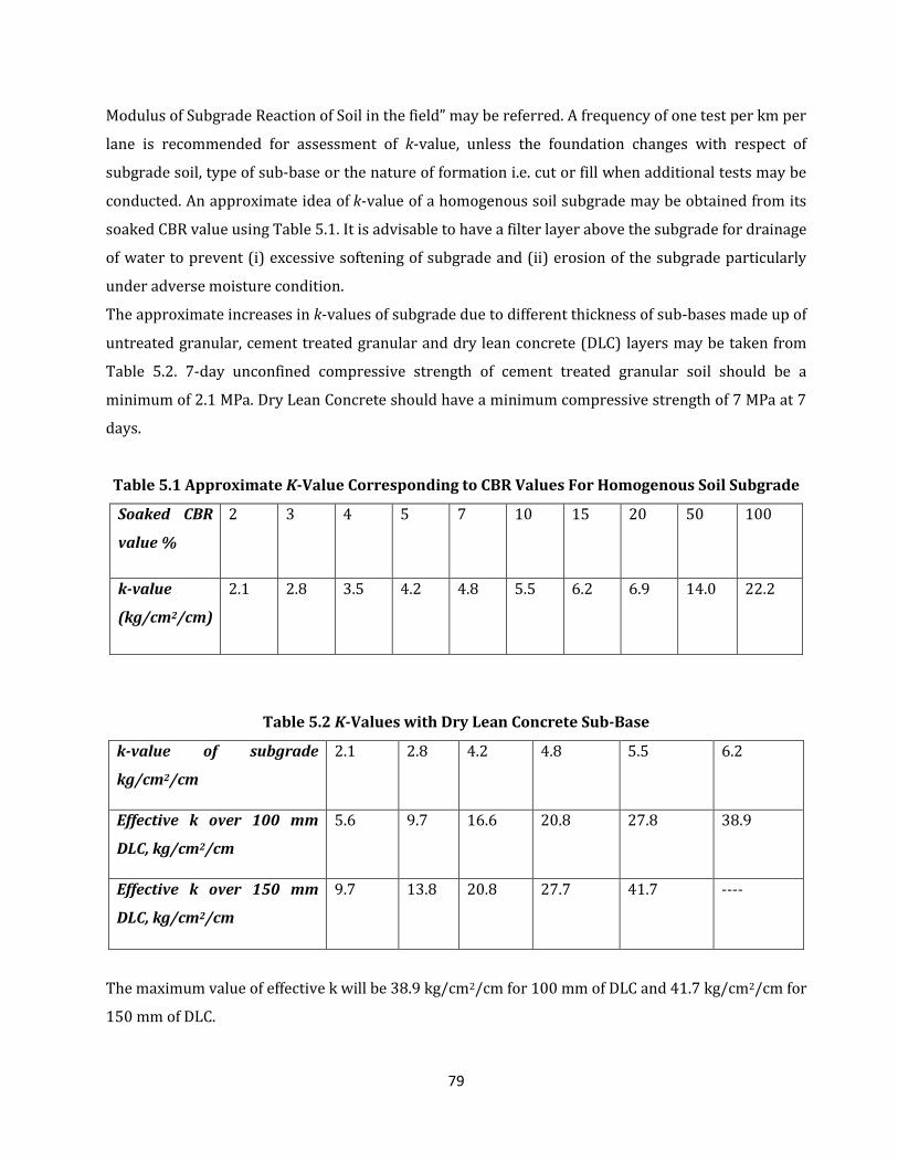
79
Modulus of Subgrade Reaction of Soil in the field” may be referred. A frequency of one test per km per
lane is recommended for assessment of k-value, unless the foundation changes with respect of
subgrade soil, type of sub-base or the nature of formation i.e. cut or fill when additional tests may be
conducted. An approximate idea of k-value of a homogenous soil subgrade may be obtained from its
soaked CBR value using Table 5.1. It is advisable to have a filter layer above the subgrade for drainage
of water to prevent (i) excessive softening of subgrade and (ii) erosion of the subgrade particularly
under adverse moisture condition.
The approximate increases in k-values of subgrade due to different thickness of sub-bases made up of
untreated granular, cement treated granular and dry lean concrete (DLC) layers may be taken from
Table 5.2. 7-day unconfined compressive strength of cement treated granular soil should be a
minimum of 2.1 MPa. Dry Lean Concrete should have a minimum compressive strength of 7 MPa at 7
days.
Table 5.1 Approximate K-Value Corresponding to CBR Values For Homogenous Soil Subgrade
Soaked CBR
value %
2 3 4 5 7 10 15 20 50 100
k-value
(kg/cm2/cm)
2.1 2.8 3.5 4.2 4.8 5.5 6.2 6.9 14.0 22.2
Table 5.2 K-Values with Dry Lean Concrete Sub-Base
k-value of subgrade
kg/cm2/cm
2.1 2.8 4.2 4.8 5.5 6.2
Effective k over 100 mm
DLC, kg/cm2/cm
5.6 9.7 16.6 20.8 27.8 38.9
Effective k over 150 mm
DLC, kg/cm2/cm
9.7 13.8 20.8 27.7 41.7 ----
The maximum value of effective k will be 38.9 kg/cm2/cm for 100 mm of DLC and 41.7 kg/cm2/cm for
150 mm of DLC.
80
5.2.2 Separation layer between sub-base and pavement:
Foundation layer below concrete slabs should be smooth to reduce the inter layer friction. A
separation membrane of minimum thickness of 125 micron polythene is recommended to reduce the
friction between concrete slabs and dry lean concrete slab-base (DLC).
5.3 CHARACTERISTICS OF CONCRETE:
5.3.1 Design Strength:
The concrete pavements fail due to bending stresses, it is necessary that their design is based on the
flexural strength of concrete. The relationship b/w the flexural strength and compressive strength
may be worked out. The mix should be so designed that the minimum structural strength
requirement in the field is met at the desired level. Thus,
= Characteristics flexural strength at 28 days.
S = Target average flexural strength at 28 days.
= Tolerance factor for the desired confidence level, known as the standard normal variate
=Expected standard deviation of field test samples; if it is not known, it may be initially
Assumed as per IS: 456-2000
Then the target average flexural strength is given as:
S = +
For pavement construction, the concrete mix should preferably be designed and controlled on the
basis of flexural strength. Flexural strength should be determined by modulus of rupture tests under
third point loading. The preferred size of the beam should be 15 cm 15 cm 70 cm when the size of
the aggregate is more than 19 mm. When the maximum size of aggregate is less than 19 mm, 10 cm
10 cm 50 cm beams may be used. IS: 516 should be referred for the test procedure.
5.3.2 Fatigue behaviour of cement concrete:
Due to repeated application of flexural stresses by the traffic loads, progressive fatigue damage takes
place in the cement concrete slab in the form of gradual development of micro-cracks especially when
the applied stress in terms of flexural strength of concrete is high. The ratio b/w the flexural stress
due to the load and the flexural strength of the concrete is known as stress ratio (SR). If the stress
ratio is less than 0.45, the concrete is expected to sustain infinite number of repetitions. As the stress
ratio increases, the number of load repetitions required to cause cracking decreases. The relation
b/w fatigue life (N) and stress ratio is given as:
N = unlimited for SR < 0.45
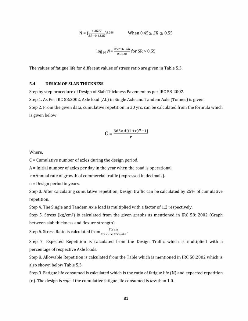
81
N = (
3.268 When 0.45
=
for SR > 0.55
The values of fatigue life for different values of stress ratio are given in Table 5.3.
5.4 DESIGN OF SLAB THICKNESS
Step by step procedure of Design of Slab Thickness Pavement as per IRC 58-2002.
Step 1. As Per IRC 58:2002, Axle load (AL) in Single Axle and Tandem Axle (Tonnes) is given.
Step 2. From the given data, cumulative repetition in 20 yrs. can be calculated from the formula which
is given below:
C =
Where,
C = Cumulative number of axles during the design period.
A = Initial number of axles per day in the year when the road is operational.
r =Annual rate of growth of commercial traffic (expressed in decimals).
n = Design period in years.
Step 3. After calculating cumulative repetition, Design traffic can be calculated by 25% of cumulative
repetition.
Step 4. The Single and Tandem Axle load is multiplied with a factor of 1.2 respectively.
Step 5. Stress (kg/cm2) is calculated from the given graphs as mentioned in IRC 58: 2002 (Graph
between slab thickness and flexure strength).
Step 6. Stress Ratio is calculated from
.
Step 7. Expected Repetition is calculated from the Design Traffic which is multiplied with a
percentage of respective Axle loads.
Step 8. Allowable Repetition is calculated from the Table which is mentioned in IRC 58:2002 which is
also shown below Table 5.3.
Step 9. Fatigue life consumed is calculated which is the ratio of fatigue life (N) and expected repetition
(n). The design is safe if the cumulative fatigue life consumed is less than 1.0.

82
Table 5.3 Stress Ratio and Allowable Repetitions in Cement Concrete
Stress Ratio Allowable
Repetitions
Stress Ratio Allowable Repetitions
0.45 6.279 0.66 5.83
0.46 1.4335 0.67 4.41
0.47 5.2 0.68 3.34
0.48 2.4 0.69 2531
0.49 1.287 0.70 1970
0.50 7.62 0.71 1451
0.51 4.85 0.72 1099
0.52 3.26 0.73 832
0.53 2.29 0.74 630
0.54 1.66 0.75 477
0.55 1.24 0.76 361
0.56 9.41 0.77 274
0.57 7.12 0.78 207
0.58 5.4 0.79 157
0.59 4.08 0.80 119
0.60 3.09 0.81 90
0.61 2.34 0.82 68
0.62 1.77 0.83 52
0.63 1.34 0.84 39
0.64 1.02 0.85 30
0.65 7.7
The slab design process as per IRC 58-2002 for the pavement quality concrete tested in the
laboratory is presented in Tables 5.5. The Table 5.4 contains the input traffic data in terms of the
expected repetitions for the single and tandem axles, for which the slab thicknesses have been
calculated. The other input parameters are as below:
Road category: Two-lane Two way National Highway Cement Concrete Pavement
Modulus of sub-grade reaction with 150mm DLC: 8kg/cm3
Elastic Modulus of Concrete: 3 x 10⁵ kg/cm2
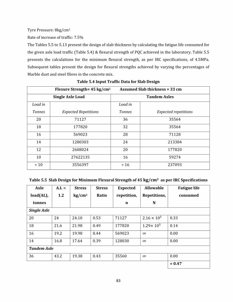
83
Tyre Pressure: 8kg/cm2
Rate of increase of traffic: 7.5%
The Tables 5.5 to 5.13 present the design of slab thickness by calculating the fatigue life consumed for
the given axle load traffic (Table 5.4) & flexural strength of PQC achieved in the laboratory. Table 5.5
presents the calculations for the minimum flexural strength, as per IRC specifications, of 4.5MPa.
Subsequent tables present the design for flexural strengths achieved by varying the percentages of
Marble dust and steel fibres in the concrete mix.
Table 5.4 Input Traffic Data for Slab Design
Flexure Strength= 45 kg/cm2 Assumed Slab thickness = 33 cm
Single Axle Load Tandem Axles
Load in
Tonnes Expected Repetitions
Load in
Tonnes Expected repetitions
20 71127 36 35564
18 177820 32 35564
16 569023 28 71128
14 1280303 24 213384
12 2608024 20 177820
10 27622135 16 59274
< 10 3556397 < 16 237093
Table 5.5 Slab Design for Minimum Flexural Strength of 45 kg/cm2 as per IRC Specifications
Axle
load(AL),
tonnes
A.L
1.2
Stress
kg/cm2
Stress
Ratio
Expected
repetition,
n
Allowable
Repetitions,
N
Fatigue life
consumed
Single Axle
20 24 24.10 0.53 71127 2.16 0.33
18 21.6 21.98 0.49 177820 1.29 0.14
16 19.2 19.98 0.44 569023 ∞ 0.00
14 16.8 17.64 0.39 128030 ∞ 0.00
Tandem Axle
36 43.2 19.38 0.43 35560 ∞ 0.00
= 0.47
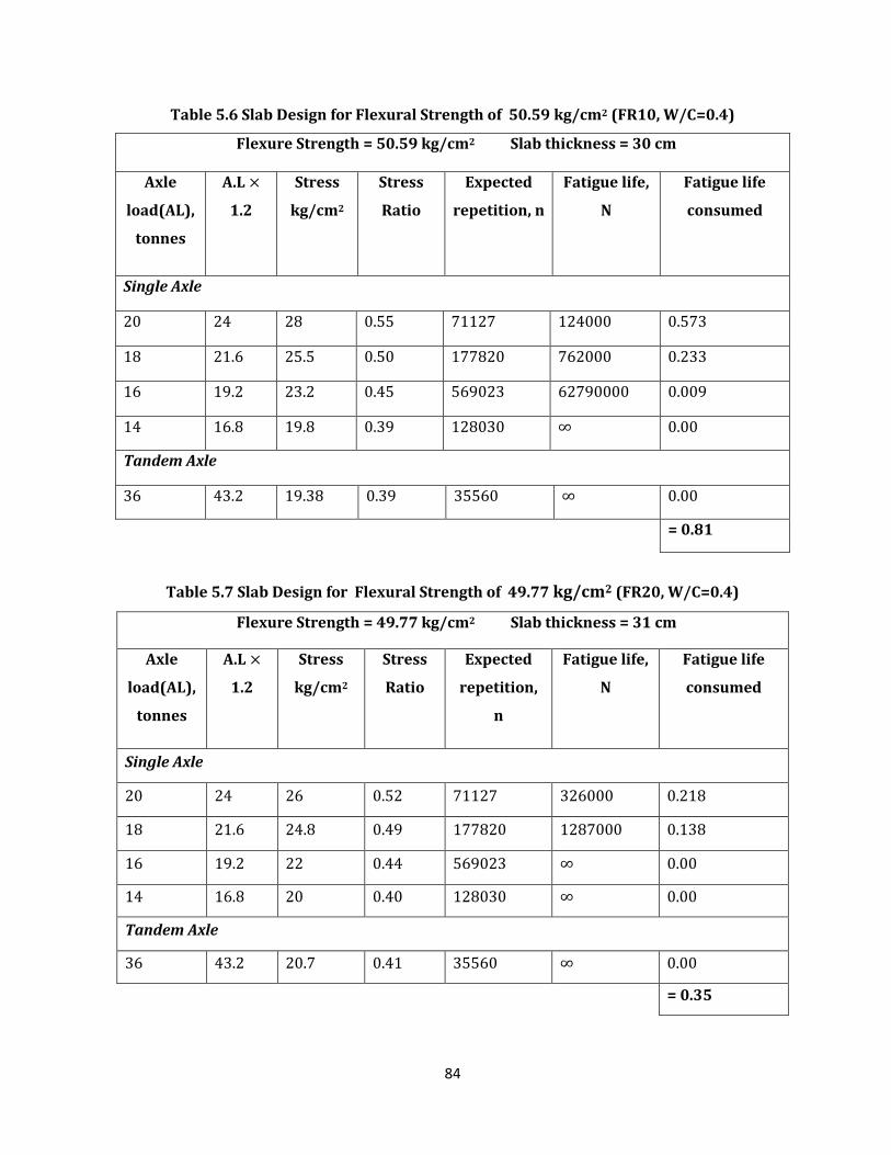
84
Table 5.6 Slab Design for Flexural Strength of 50.59 kg/cm2 (FR10, W/C=0.4)
Flexure Strength = 50.59 kg/cm2 Slab thickness = 30 cm
Axle
load(AL),
tonnes
A.L
1.2
Stress
kg/cm2
Stress
Ratio
Expected
repetition, n
Fatigue life,
N
Fatigue life
consumed
Single Axle
20 24 28 0.55 71127 124000 0.573
18 21.6 25.5 0.50 177820 762000 0.233
16 19.2 23.2 0.45 569023 62790000 0.009
14 16.8 19.8 0.39 128030 ∞ 0.00
Tandem Axle
36 43.2 19.38 0.39 35560 ∞ 0.00
= 0.81
Table 5.7 Slab Design for Flexural Strength of 49.77 kg/cm2 (FR20, W/C=0.4)
Flexure Strength = 49.77 kg/cm2 Slab thickness = 31 cm
Axle
load(AL),
tonnes
A.L
1.2
Stress
kg/cm2
Stress
Ratio
Expected
repetition,
n
Fatigue life,
N
Fatigue life
consumed
Single Axle
20 24 26 0.52 71127 326000 0.218
18 21.6 24.8 0.49 177820 1287000 0.138
16 19.2 22 0.44 569023 ∞ 0.00
14 16.8 20 0.40 128030 ∞ 0.00
Tandem Axle
36 43.2 20.7 0.41 35560 ∞ 0.00
= 0.35
85
Table 5.8 Analysis of saving of materials for designed flexure of 45 kg/cm2
w/c = 0.40
Pavement
Thickness
Saving in
Pavement
Thickness
Saving of
concrete
per k.m.
length (2-
lanes)
Saving in
Cement
Content
Saving in
Fine
Aggregate
Saving in
Coarse
Aggregate
For flexure
45 kg/cm2
330 mm
10% F.A.
[FR10]
300 mm 30mm 225 m3 87750 kg
+87750 kg
=175500 kg
160425 kg 242775 kg
20% F.A
[FR20]
310 mm 20mm 150 m3
58500 kg +181350 kg =239850 kg
106950 kg 161850 kg
Table 5.9 Slab Design for Minimum Flexural Strength of 50 kg/cm2 (W/C = 0.35)
Flexure Strength = 50 kg/cm2 Slab thickness = 30 cm
Axle
load(AL),
tonnes
A.L
1.2
Stress
kg/cm2
Stress
Ratio
Expected
repetition, n
Fatigue life,
N
Fatigue life
consumed
Single Axle
20 24 28 0.56 71127 941000 0.075
18 21.6 25.5 0.51 177820 485000 0.366
16 19.2 23.2 0.46 569023 14335000 0.039
14 16.8 19.8 0.39 128030 ∞ 0.000
Tandem Axle
36 43.2 19.38 0.43 35560 ∞ 0.000
= 0.48
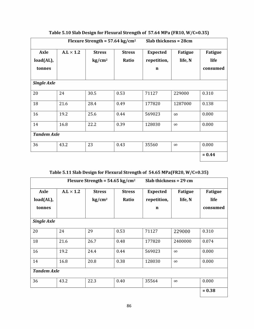
86
Table 5.10 Slab Design for Flexural Strength of 57.64 MPa (FR10, W/C=0.35)
Flexure Strength = 57.64 kg/cm2 Slab thickness = 28cm
Axle
load(AL),
tonnes
A.L 1.2 Stress
kg/cm2
Stress
Ratio
Expected
repetition,
n
Fatigue
life, N
Fatigue
life
consumed
Single Axle
20 24 30.5 0.53 71127 229000 0.310
18 21.6 28.4 0.49 177820 1287000 0.138
16 19.2 25.6 0.44 569023 ∞ 0.000
14 16.8 22.2 0.39 128030 ∞ 0.000
Tandem Axle
36 43.2 23 0.43 35560 ∞ 0.000
= 0.44
Table 5.11 Slab Design for Flexural Strength of 54.65 MPa(FR20, W/C=0.35)
Flexure Strength = 54.65 kg/cm2 Slab thickness = 29 cm
Axle
load(AL),
tonnes
A.L 1.2 Stress
kg/cm2
Stress
Ratio
Expected
repetition,
n
Fatigue
life, N
Fatigue
life
consumed
Single Axle
20 24 29 0.53 71127 229000 0.310
18 21.6 26.7 0.48 177820 2400000 0.074
16 19.2 24.4 0.44 569023 ∞ 0.000
14 16.8 20.8 0.38 128030 ∞ 0.000
Tandem Axle
36 43.2 22.3 0.40 35564 ∞ 0.000
= 0.38
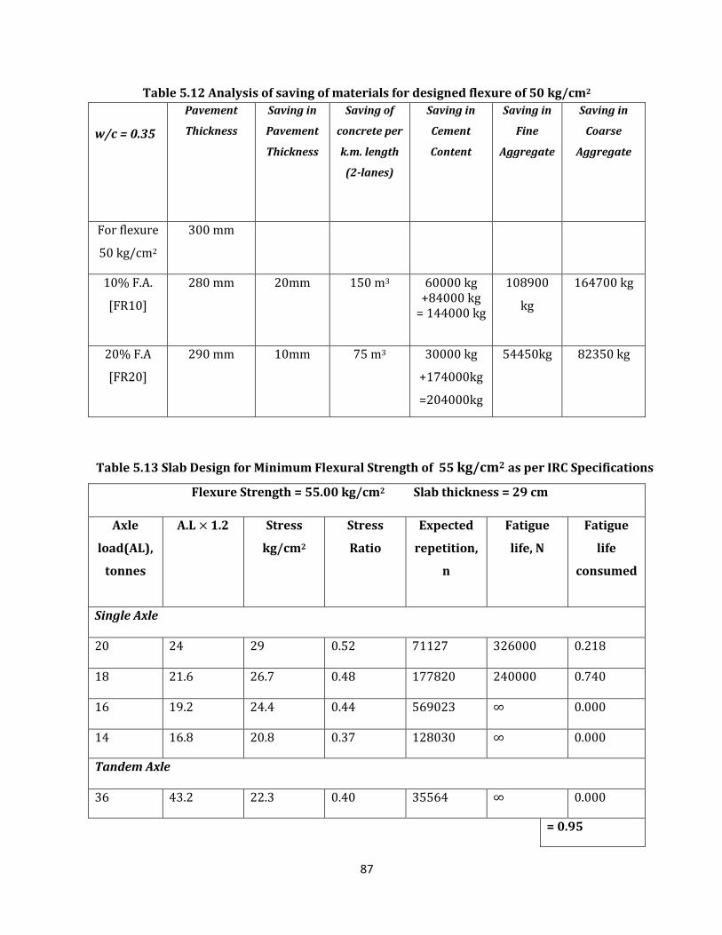
87
Table 5.12 Analysis of saving of materials for designed flexure of 50 kg/cm2
w/c = 0.35
Pavement
Thickness
Saving in
Pavement
Thickness
Saving of
concrete per
k.m. length
(2-lanes)
Saving in
Cement
Content
Saving in
Fine
Aggregate
Saving in
Coarse
Aggregate
For flexure
50 kg/cm2
300 mm
10% F.A.
[FR10]
280 mm 20mm 150 m3 60000 kg +84000 kg
= 144000 kg
108900
kg
164700 kg
20% F.A
[FR20]
290 mm 10mm 75 m3 30000 kg
+174000kg
=204000kg
54450kg 82350 kg
Table 5.13 Slab Design for Minimum Flexural Strength of 55 kg/cm2 as per IRC Specifications
Flexure Strength = 55.00 kg/cm2 Slab thickness = 29 cm
Axle
load(AL),
tonnes
A.L 1.2 Stress
kg/cm2
Stress
Ratio
Expected
repetition,
n
Fatigue
life, N
Fatigue
life
consumed
Single Axle
20 24 29 0.52 71127 326000 0.218
18 21.6 26.7 0.48 177820 240000 0.740
16 19.2 24.4 0.44 569023 ∞ 0.000
14 16.8 20.8 0.37 128030 ∞ 0.000
Tandem Axle
36 43.2 22.3 0.40 35564 ∞ 0.000
= 0.95
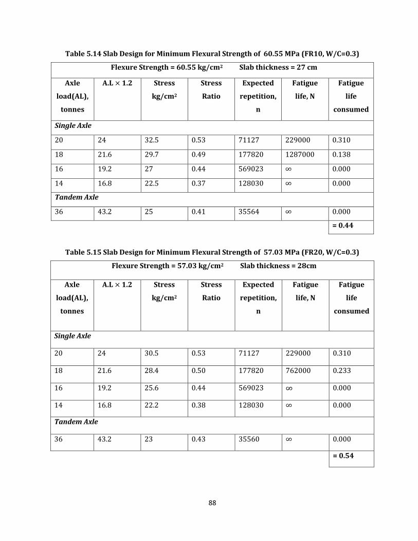
88
Table 5.14 Slab Design for Minimum Flexural Strength of 60.55 MPa (FR10, W/C=0.3)
Flexure Strength = 60.55 kg/cm2 Slab thickness = 27 cm
Axle
load(AL),
tonnes
A.L 1.2 Stress
kg/cm2
Stress
Ratio
Expected
repetition,
n
Fatigue
life, N
Fatigue
life
consumed
Single Axle
20 24 32.5 0.53 71127 229000 0.310
18 21.6 29.7 0.49 177820 1287000 0.138
16 19.2 27 0.44 569023 ∞ 0.000
14 16.8 22.5 0.37 128030 ∞ 0.000
Tandem Axle
36 43.2 25 0.41 35564 ∞ 0.000
= 0.44
Table 5.15 Slab Design for Minimum Flexural Strength of 57.03 MPa (FR20, W/C=0.3)
Flexure Strength = 57.03 kg/cm2 Slab thickness = 28cm
Axle
load(AL),
tonnes
A.L 1.2 Stress
kg/cm2
Stress
Ratio
Expected
repetition,
n
Fatigue
life, N
Fatigue
life
consumed
Single Axle
20 24 30.5 0.53 71127 229000 0.310
18 21.6 28.4 0.50 177820 762000 0.233
16 19.2 25.6 0.44 569023 ∞ 0.000
14 16.8 22.2 0.38 128030 ∞ 0.000
Tandem Axle
36 43.2 23 0.43 35560 ∞ 0.000
= 0.54
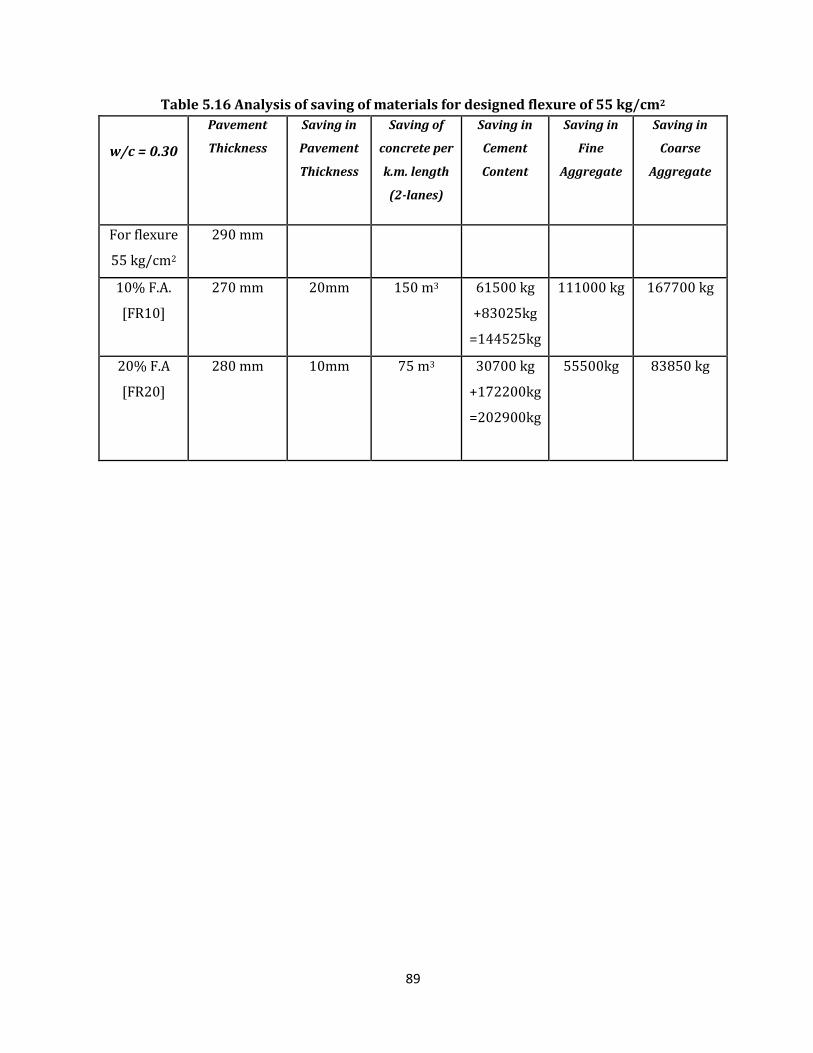
89
Table 5.16 Analysis of saving of materials for designed flexure of 55 kg/cm2
w/c = 0.30
Pavement
Thickness
Saving in
Pavement
Thickness
Saving of
concrete per
k.m. length
(2-lanes)
Saving in
Cement
Content
Saving in
Fine
Aggregate
Saving in
Coarse
Aggregate
For flexure
55 kg/cm2
290 mm
10% F.A.
[FR10]
270 mm 20mm 150 m3 61500 kg
+83025kg
=144525kg
111000 kg 167700 kg
20% F.A
[FR20]
280 mm 10mm 75 m3 30700 kg
+172200kg
=202900kg
55500kg 83850 kg
90
CHAPTER-6
CONCLUSIONS
6.1 GENERAL
The present study was undertaken to investigate the effect of partial replacement of cement with fly
ash and rice husk ash on compressive strength and flexural strength of concrete mix. Cement was
partially replaced by fly ash at three different levels of replacement i.e. 10%, 20% and 30% and same
with rice husk ash as well as with combined replacements of fly ash and rice husk ash. Tests were
performed after 28 days of curing of concrete. Cubes and beams were prepared for determining
compressive strength and flexural strength of concrete with different water-cement ratio as 0.30,
0.35 and 0.40 for min required flexural strengths 5.5 N/mm2 5 N/mm2 4.5N/mm2 respectively. Super-
plasticizer was used in all the mixes at 1% level by weight of cementitious material.
6.2 CONCLUSIONS
From the experimental results, the conclusions of compressive strength, flexural strength and the
pavement quality concrete slab thickness are concluded as under:
6.2.1 COMPRESSIVE STRENGTH
The mixes with only fly ash replacement has a lesser rate of increase in strength from 7days
to 28 days despite the fact that they have high initial strength, than the mixes with rice husk
ash replacement only. The mixes with the inclusion of both rice husk ash and fly ash as
replacement material show the highest rate of increase of compressive strength for all water
to cement ratios which indicates indicates that pozzolanic activity initiates early for such
mixes.
Concrete mix with up to 30% percent replacement of cement with fly ash for all water-cement
ratios have higher compressive strengths than minimum required as per MoRT&H
specifications.
Concrete mixes with 10% replacement of rice husk ash in w/c= 0.3 have higher compressive
strengths than minimum required as per MoRT&H specifications.
Concrete mixes with combined replacement of 10% each of fly ash and rice husk ash in w/c=
0.3 showed higher compressive strengths than minimum required as per MoRT&H
specifications.
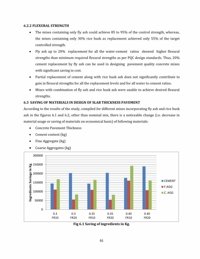
91
6.2.2 FLEXURAL STRENGTH
The mixes containing only fly ash could achieve 85 to 95% of the control strength, whereas,
the mixes containing only 30% rice husk as replacement achieved only 55% of the target
controlled strength.
Fly ash up to 20% replacement for all the water-cement ratios showed higher flexural
strengths than minimum required flexural strengths as per PQC design standards. Thus, 20%
cement replacement by fly ash can be used in designing pavement quality concrete mixes
with significant saving in cost.
Partial replacement of cement along with rice husk ash does not significantly contribute to
gain in flexural strengths for all the replacement levels and for all water to cement ratios.
Mixes with combination of fly ash and rice husk ash were unable to achieve desired flexural
strengths.
6.3 SAVING OF MATERIALS IN DESIGN OF SLAB THICKNESS PAVEMENT
According to the results of the study, compiled for different mixes incorporating fly ash and rice husk
ash in the figures 6.1 and 6.2, other than nominal mix, there is a noticeable change (i.e. decrease in
material usage or saving of materials on economical basis) of following materials:
Concrete Pavement Thickness
Cement content (kg)
Fine Aggregate (kg)
Coarse Aggregates (kg)
Fig 6.1 Saving of ingredients in Kg.
0
50000
100000
150000
200000
250000
300000
0.3FR10
0.3FR20
0.35FR10
0.35FR20
0.40FR10
0.40FR20
Ing
red
ien
ts S
av
ing
s in
Kg
CEMENT
F.AGG
C. AGG
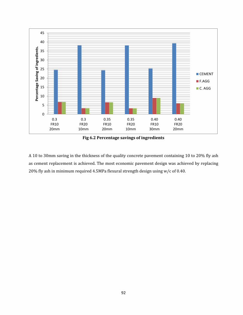
92
Fig 6.2 Percentage savings of ingredients
A 10 to 30mm saving in the thickness of the quality concrete pavement containing 10 to 20% fly ash
as cement replacement is achieved. The most economic pavement design was achieved by replacing
20% fly ash in minimum required 4.5MPa flexural strength design using w/c of 0.40.
0
5
10
15
20
25
30
35
40
45
0.3FR10
20mm
0.3FR20
10mm
0.35FR10
20mm
0.35FR20
10mm
0.40FR10
30mm
0.40FR20
20mm
Pe
rce
nta
ge S
avin
g o
f in
gre
die
nts
.
CEMENT
F.AGG
C. AGG
93
CHAPTER- 7
REFERENCES
Atiş, C. D., Kilic, A., &Sevim, U. K. (2004) "Strength and shrinkage properties of mortar
containing a nonstandard high-calcium fly ash". Cement and Concrete Research, 34(1), 99-102.
Brown, J.H. (1982) "The strength and workability of concrete with PFA substitution", In:
Proceedings International Symposium on the Use of PFA in Concrete, pp. 151–161.
Bui, D. D., Hu, J., & Stroeven, P. (2005) "Particle size effect on the strength of rice husk ash
blended gap-graded Portland cement concrete", Cement and Concrete Composites, 27(3), 357-
366.
Bui, D.D., Hu, J. and Stroeven, P. (2005) “Particle Size Effect On The Strength Of Rice Husk Ash
Blended Gap-Graded Portland Cement Concrete”, Cement & Concrete Composites 27, pp357–
366.
Carette, G. G., &Malhotra, V. M. (1984) "Characterization of Canadian fly ashes and their
performance in concrete", Division Report, MRP/MSL, 84-137.
Chalee, W., Teekavanit, M., Kiattikomol, K., Siripanichgorn, A., &Jaturapitakkul, C.
(2007)"Effect of W/C ratio on covering depth of fly ash concrete in marine
environment", Construction and Building Materials, 21(5), 965-971.
Compton, F. R., &Macinnis, C. (1952)"Field trial of fly ash concrete", Ontario Hydro Research
News, 18-21.
Della, V. P., Kühn, I., &Hotza, D. (2002)"Rice husk ash as an alternate source for active silica
production", Materials Letters, 57(4), 818-821.
Demirboğa, R., Türkmen, İ., &BurhanKarakoç, M. (2007) "Thermo-mechanical properties of
concrete containing high-volume mineral admixtures", Building and Environment, 42(1), 49-
354.
Ellis, WE Jr, Rigs, E.H., Butler, W.B. (1991)"Comparative results of utilization of fly ash, silica
fume and GGBS in reducing the chloride permeability of concrete". In: Proceedings of the 2nd
CANMET/ACI International Conference on Durability of Concrete, Montreal, Canada. ACI SP
126(1), 443–457
Ganesan, K., Rajagopal, K., &Thangavel, K. (2008) "Rice husk ash blended cement: assessment
of optimal level of replacement for strength and permeability properties of
concrete", Construction and Building Materials, 22(8), 1675-1683.
94
Gebler, S. H., &Klieger, P. (1983) "Effect of fly ash on the air-void stability of concrete (No.
RD085. 01T)", Portland Cement Association.
Givi, A.N., Rashid, S.A., Aziz, F.N.A. and Salleh, M.A.M. (2010) “Assessment of the effects of rice
husk ash particle size on strength, water permeability and workability of binary blended
concrete”, Construction and Building Materials 24 pp. 2145–2150.
Habeeb, G.A. and Mahmud, H.B. (2010) “Study on Properties of Rice Husk Ash and Its Use as
Cement Replacement Material”, Materials Research 13 pp. 185-190.
Haque, M.N., Langan, B.W., Ward, M.A. (1988) "High fly ash concretes. ACI Mater.8(1), 54–60
Ho, D. W. S., & Lewis, R. K. (1983)", Carbonation of concrete incorporating fly ash or a
chemical admixture. ACI Special Publication, 79.
IS: 1237 (1980): Method for testing abrasion resistance of concrete. Bureau of Indian
Standards (BIS), New Delhi, India
IRC: 58-2002, “Guideline for Design of Rigid Pavements for Highways.” The Indian Road
Congress, New Delhi, 2002.
IS: 456-2000: Code of practice- plain and reinforced concrete, Bureau of Indian Standard, New
Delhi-2000.
IS: 516-1959 (Reaffirmed 2004): Methods of tests for strength of concrete, Bureau of Indian
Standard, New Delhi-2004.
IS: 10262-1982 (Reaffirmed 2004): Recommended guidelines for concrete mix design, Bureau
of Indian Standard, New Delhi-2004
IS: 8112-1989 (Reaffirmed 2005): Specification for 43 Grade Ordinary Portland Cement,
Bureau of Indian Standard, New Delhi-2005.
IS: 9103-1999 (Reaffirmed 2004): Concrete Admixtures-Specifications, Bureau of Indian
Standard, New Delhi-2004.
IS: 383-1970: Specification for Coarse and Fine Aggregates from Natural Sources for Concrete,
Bureau of Indian Standard, New Delhi-1970.
IS: 1199-1959 (Reaffirmed 1999): Methods of Sampling and Analysis of Concrete, Bureau of
Indian Standard, New Delhi-1999.
IS: 2386 (Part I, III)-1963: Methods of Test for Aggregates for Concrete, Bureau of Indian
Standard, New Delhi-1963.
IS: 4031 (Part 4, 5&6)-1988: Methods of Physical Tests for Hydraulic Cement, Bureau of
Indian Standard, New Delhi-1988.
95
Joshi, R. C., &Lohtia, R. P. (1993) "Effects of premature freezing temperatures on compressive
strength, elasticity and microstructure of high volume fly ash concrete", Third Canadian
Symposium on Cement and Concrete, Ottawa, Canada.
Khan, R., Jabbar, A., Ahmad, I., Khan, W., Khan, A.N. and Mirza, J. (2011) “Reduction in
environmental problems using rice-husk ash in concrete”, Construction and Building Materials
30, pp. 360–365.
Kishore, R., Bhikshma, V. and Prakash, P.J. (2011) “Study on Strength Characteristics of High
Strength Rice Husk Ash Concrete”, Procedia Engineering 14, pp. 2666–2672.
Lohtia, R. P., Nautiyal, B. D., & Jain, O. P. (1976) "Creep af Fly Ash Concrete" In ACI Journal
Proceedings (Vol. 73, No. 8).ACI.
Ministry of Road Transport and Highways (specifications for road and bridge works).
Mehta, P. K.(2000) "Sulfate attack on concrete: separating myths from reality."Concrete
International 22(8): 57-61.
Nagrale, S.D., Hajare, H. and Modak, P.R. (2012) “Utilization of Rice Husk Ash”,International
Journal of Engineering Research and Applications (IJERA). Vol. 2, Issue 4, pp.001-005
Naik, T. R., & Singh, S. S. (1991, March) "Superplasticized high-volume fly ash structural
concrete. In Presented and Preprint Published at the ASCE Energy Conference on Energy in
1990s, Pittsburgh, PA.
Naik, T. R., Singh, S. S., &Hossain, M. M. (1994) "Permeability of concrete containing large
amounts of fly ash", Cement and Concrete Research, 24(5), 913-922.
Owens, P. L. (1979). Fly ash and its usage in concrete. Concrete, 13(7).
Ramzanianpour, A., Mahdikhani, M., &Ahmadibeni, G. (2009)"The effect of rice husk ash on
mechanical properties and durability of sustainable concretes", International Journal of Civil
Engineering, 7(2), 83-91.
Rukzon, S. and Chindaprasirt, P. (2010) “Strength and Carbonation Model of Rice Husk Ash
Cement Mortar with Different Fineness.” Journal of Materials in Civil Engineering ASCE22, pp.
253-259.
Saraswathy, V., Muralidharan, S., Thangavel, K., &Srinivasan, S. (2003) "Influence of activated
fly ash on corrosion-resistance and strength of concrete" Cement and Concrete
Composites, 25(7), 673-680.
Siddique, R. (2003) "Effect of fine aggregate replacement with Class F fly ash on the
mechanical properties of concrete", Cement and Concrete Research,33(4), 539-547.
Siddique, R. (2008) "Waste Materials and By-Products in Concrete"
96
Siddique, R. (2003) "Effect of fine aggregate replacement with Class F fly ash on the abrasion
resistance of concrete", Cement and concrete research, 33(11), 1877-1881.
Sivasundaram, V., Carette, G. G., &Malhotra, V. M. (1990) "Selected properties of high volume
fly ash concretes", Concrete International, 12(10), 47-50.
Tashima, M.M., Carlos, A. R. S., Jorge, L.A. AND Barbosa, M.B. (2010) “The Possibility Of Adding
The Rice Husk Ash (RHA) To The Concrete.” Brazil, pp. 3743-1160
Uduweriya, R. B.Y. B., Subash, C., Sulfy, M. M. A., and Silva, S.D. (2010) “Investigation of
Compressive Strength of Concrete Containing Rice-Husk-Ash”, International Conference on
Sustainable Built Environment (ICSBE-2010)Kandy, pp. 13-14
Virtanen, J. (1983) "Freeze-thaw resistance of concrete containing blast-furnace slag, fly ash
or condensed silica fume", ACI Special Publication, 79.
Yuan, R.Z., Jin, S.X., Qian, J.C. (1982) "Effects of fly ash on rheology of fresh cement paste",
Materials and Research Society Symposium Proceedings, pp. 182–191
Zhang, M. H., &Malhotra, V. M. (1996) "High-performance concrete incorporating rice husk
ash as a supplementary cementing material" ACI Materials Journal, 93(6).
Zhang, M.H., Lastra, R. and Malhotra, V.M.(1996) “Rice-Husk Ash Paste And Concrete: Some
Aspects Of Hydration And The Microstructure Of The Interfacial Zone Between The Aggregate
And Paste”, Cement and Concrete Research, Vol. 26, No. 6, pp. 963-977.