Embed Size (px)
Citation preview

1CMP Research Lab
Effect of kinematics and abrasive
particle dynamics on material removal
rate uniformity during polishing
Armin Saeedi Vahdat1,2 and S V Babu2
1Dept. of Mechanical and Aeronautical Engineering
2Center for Advanced Material Processing (CAMP)
Clarkson University
Potsdam, New York 13699-5725
April16, 2015

2CMP Research Lab
Motivation and Objective
Scaling down the structures
and increasing wafer size MRR uniformity becomes
more challenging
CMP kinematics based on slurry
distribution and particle
trajectories have a big impact on
MRR profiles.
(Pressure and temperature profiles
are also very important)

3CMP Research Lab
Chemical Mechanical Polishing Kinematics
e0 : Distance between pad and wafer centers, r0 : Wafer radius
et : Carrier oscillatory motion function
ωp : Platen rotational/angular
velocity ωw : wafer rotational/angular
velocity
Rotary Dynamics
Reciprocation Dynamics
ωw tωp t
e0X, x
Y
y
et r0
wafer
Pad

4CMP Research Lab
Velocity Field on Wafer SurfaceRelative velocity of a
point on the wafer:0(e e )A p t p tv r r e
rr r r rr r r&
ωw tωp t
e0X, x
Y
y
et r0
waferr A
Pad
2 2
0 0 0(1 ) / 1 (1 ) /A pv e y e x e
2 2
0 0 0 0 0/ ( ) (1 ) / 1 / (1 ) /A p t p tv e e e y e e e x e &
For typical rotary-type
polishers:
0 0,t p te e e e &
/w p where

5CMP Research Lab
Velocity Field on Wafer Surface
When α = 1 (ωp = ωw)
2 2
0 0 0
0 0
( (1 ) / ) (1 (1 ) / )A pv e y e x e
1 4 2 4 3 1 4 2 4 3
Uniform velocity field all over the wafer
0A pv e
Assuming uniform pressure distribution, Preston’s equation
suggests uniform MRR:
(x, y) (x, y) (x, y)p AMRR k v p0(x, y) .p pMRR k p e cont
However experimental results suggests α = 1 is
not a proper velocity ratio option in order to get
uniform MRR profile.

6CMP Research Lab
Particle Trajectories and MRRParticles trapped between pad
asperities and wafer are active
particles
activeinactive
MRR uniformity depends on:
Active particles trajectories
distribution
Material removed along each
trajectory (particle size)
Non active abrasives cause
zero/negligible MRR

7CMP Research Lab
Description of a Particle Location
Initial location of each active particle of pad:
0
0
cos
sin
A
A
XR
Y
0 0R e r
0m m
2 2 21 0 0
0
cos2
m
R e r
R e
Location of all Active particles
participating in MRR on wafer
follows these conditions
r0
φ0
RA
X, x
Y y
φm
e0
8CMP Research Lab
φ0+ωp tR
A
Y
y
et
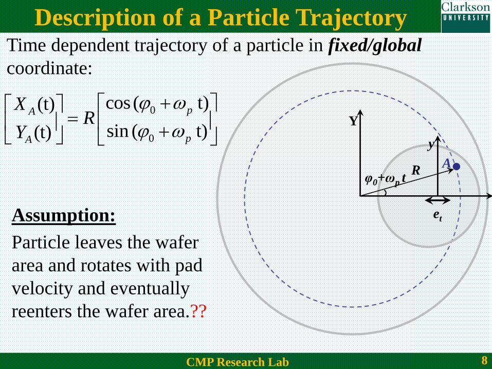
Description of a Particle TrajectoryTime dependent trajectory of a particle in fixed/global
coordinate:
0
0
cos ( t)(t)
sin ( t)(t)
pA
pA
XR
Y
Assumption:
Particle leaves the wafer
area and rotates with pad
velocity and eventually
reenters the wafer area.??

9CMP Research Lab
Description of a Particle Trajectory
Time-dependent particle locations
in fixed and moving coordinates
are related as:
ωw t X
Yy yʹ
x
xʹ
A
e0 +et
φ0+ωp t
0(t) (t)
(t) (t) 0
A A t
A A
X x e e
Y y
cos( t) sin( t)(t) (t)
sin( t) cos( t)(t) (t)
p pA A
p pA A
x x
y y
Carrier oscillatory motion is described using its amplitude and
frequency:
sin ( )t e ee A tZhao, Dewen, et al. "Kinematic optimization for chemical mechanical polishing based on statistical analysis of particle trajectories." Semiconductor
Manufacturing, IEEE Transactions on 26.4 (2013): 556-563.
10CMP Research Lab
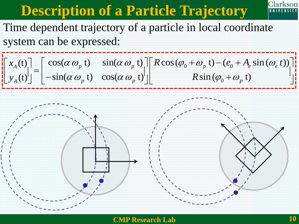
Description of a Particle Trajectory
0 0
0
cos( t) sin( t) cos ( t) ( sin ( ))(t)
sin( t) cos( t) sin ( t)(t)
p p p e eA
p p pA
R e A tx
Ry
Time dependent trajectory of a particle in local coordinate
system can be expressed:

11CMP Research Lab
Five Particle Trajectories (No Oscillation)
-100 0 100-150
-100
-50
0
50
100
150
x (mm)
y (
mm
)
-100 0 100-150
-100
-50
0
50
100
150
x (mm)
y (
mm
)
Five particles are located
on pad asperities
When α = 1 (ωp = ωw)

12CMP Research Lab
Five Particle Trajectories (No Oscillation)α=0.90
-100 0 100-150
-100
-50
0
50
100
150
x (mm)
y (
mm
)
-100 0 100-150
-100
-50
0
50
100
150
x (mm)
y (
mm
)
-100 0 100-150
-100
-50
0
50
100
150
x (mm)
y (
mm
)
-100 0 100-150
-100
-50
0
50
100
150
x (mm)
y (
mm
)
α=0.91
α=0.92
α=0.93
13CMP Research Lab
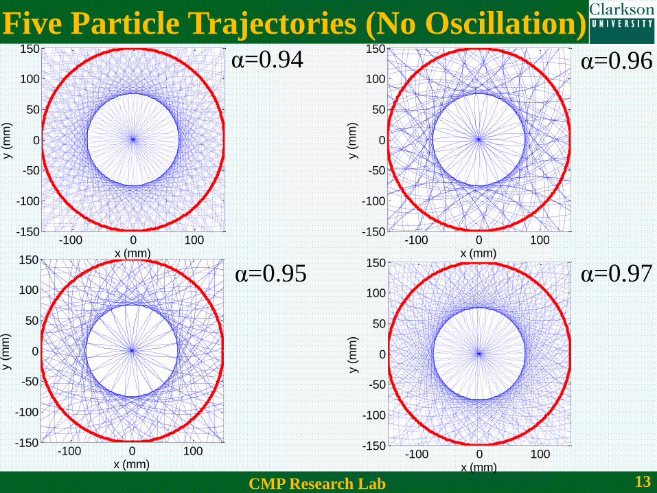
Five Particle Trajectories (No Oscillation)α=0.94
α=0.95
α=0.96
α=0.97
-100 0 100-150
-100
-50
0
50
100
150
x (mm)
y (
mm
)
-100 0 100-150
-100
-50
0
50
100
150
x (mm)
y (
mm
)
-100 0 100-150
-100
-50
0
50
100
150
x (mm)
y (
mm
)
-100 0 100-150
-100
-50
0
50
100
150
x (mm)
y (
mm
)
14CMP Research Lab
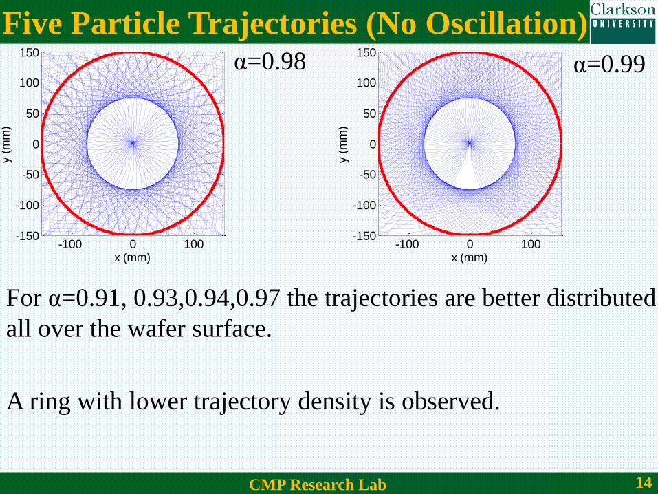
Five Particle Trajectories (No Oscillation)α=0.98 α=0.99
-100 0 100-150
-100
-50
0
50
100
150
x (mm)
y (
mm
)
-100 0 100-150
-100
-50
0
50
100
150
x (mm)
y (
mm
)
For α=0.91, 0.93,0.94,0.97 the trajectories are better distributed
all over the wafer surface.
A ring with lower trajectory density is observed.

15CMP Research Lab
Five Particle Trajectories (No Oscillation)
-100 0 100-150
-100
-50
0
50
100
150
x (mm)
y (
mm
)-100 0 100
-150
-100
-50
0
50
100
150
x (mm)
y (
mm
)
-100 0 100-150
-100
-50
0
50
100
150
x (mm)
y (
mm
)
-100 0 100-150
-100
-50
0
50
100
150
x (mm)
y (
mm
)The observed ring is an
artifact which is
induced due to the initial
particle locations
16CMP Research Lab
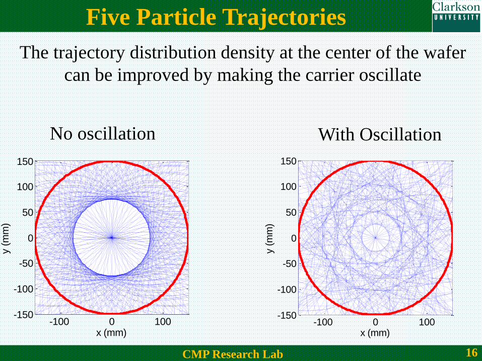
Five Particle Trajectories
No oscillation With Oscillation
The trajectory distribution density at the center of the wafer
can be improved by making the carrier oscillate
-100 0 100-150
-100
-50
0
50
100
150
x (mm)
y (
mm
)
-100 0 100-150
-100
-50
0
50
100
150
x (mm)
y (
mm
)

17CMP Research Lab
100 Particle Trajectories
When number of particles increase, the trajectory distribution
appears uniform but it is not.
-100 0 100-150
-100
-50
0
50
100
150
x (mm)
y (
mm
)
-10 -5 0 5 10-10
-5
0
5
10
x (mm)
y (
mm
)
Therefore a quantitative technique is required to measure the
distribution of particle trajectories across the wafer.

18CMP Research Lab
Kinematics Parameters and Sliding Length
n
Particle 1
t=t0 + ∆tSliding
distance L11
nn Particle 1
t=t0 + 2∆t
Sliding
distance
L12
Sliding distance of each particle inside each
area element is calculated during polishing
time.
n
Particle 2
t=t0 + ∆t
Sliding
distance L21
n
n
Particle 2
t=t0 + 2∆t
Sliding
distance L22

19CMP Research Lab
Sliding Distance, MRR and WIWNU
( , ) ( , ) ( , )pV x y k p x y L x y
( , ) ( , )( ) ( , )v p
p p
V x y L x yMRR k R p x y
T T
Uniform pressure profile ( )( , )
p
v
p
const
k R pMRR L x y
T
14 2 43
Hence Sliding distance distribution is an indicator of WIWNU
(%) 100 100MRR L
mean mean
WIWNUMRR L
Material volume removed based on particle trajectory length:
Mono-dispersed particles

20CMP Research Lab
WIWNU vs Active Particle Number
Using large number of particles in simulations is impractical
So determine the number of active particles that leads to a
realistic simulation
102
104
106
-10
0
10
20
30
Particles Number
WIW
NU
(%)
n =10,000 is a good choice for
number of particles
Zhao, Dewen, et al. "Kinematic optimization for chemical mechanical polishing based on statistical analysis of particle trajectories." Semiconductor
Manufacturing, IEEE Transactions on 26.4 (2013): 556-563.
21CMP Research Lab
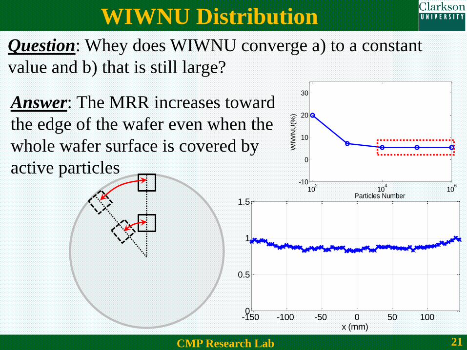
WIWNU Distribution
Question: Whey does WIWNU converge a) to a constant
value and b) that is still large?
102
104
106
-10
0
10
20
30
Particles Number
WIW
NU
(%)
Answer: The MRR increases toward
the edge of the wafer even when the
whole wafer surface is covered by
active particles
-150 -100 -50 0 50 1000
0.5
1
1.5
x (mm)
Norm
aliz
ed S
lidin
g D
ista
nce
22CMP Research Lab
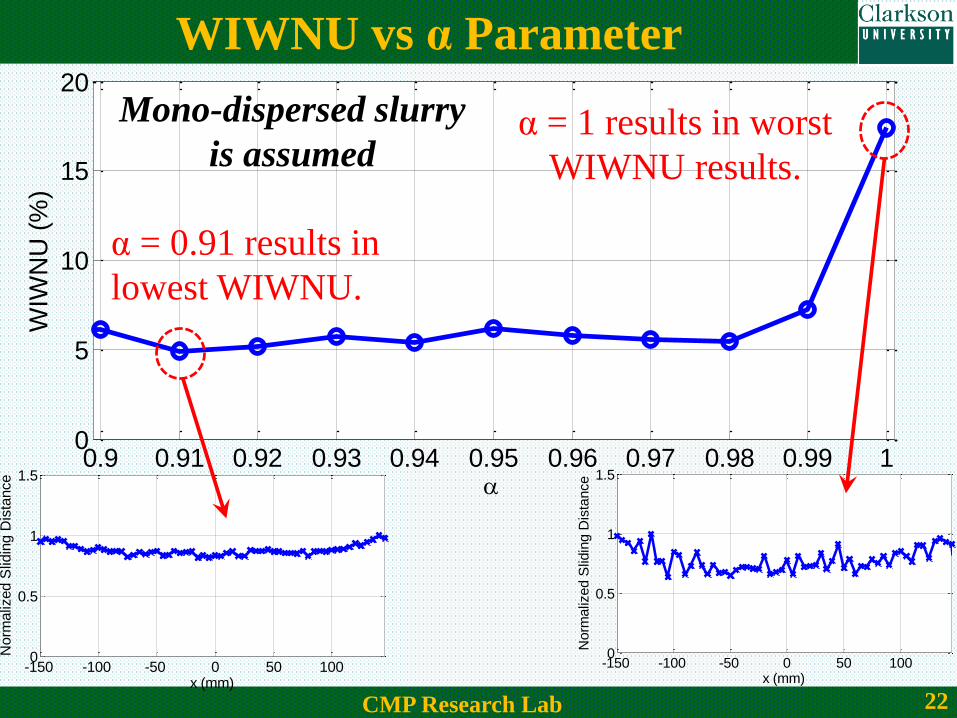
WIWNU vs α Parameter
0.9 0.91 0.92 0.93 0.94 0.95 0.96 0.97 0.98 0.99 10
5
10
15
20
WIW
NU
(%
)
α = 0.91 results in
lowest WIWNU.
α = 1 results in worst
WIWNU results.
-150 -100 -50 0 50 1000
0.5
1
1.5
x (mm)
Norm
aliz
ed S
lidin
g D
ista
nce
-150 -100 -50 0 50 1000
0.5
1
1.5
x (mm)
Norm
aliz
ed S
lidin
g D
ista
nce
Mono-dispersed slurry
is assumed

23CMP Research Lab
WIWNU vs Oscillatory Motion
1 2 3 4 5 6 7 8 9 102
3
4
5
6
7
p /
e
WIW
NU
(%)
0 0.1 0.2 0.3 0.4 0.5 0.6 0.73
4
5
6
7
Ae / r
0
WIW
NU
(%)
sin ( )t e ee A t
6
p
e
Oscillatory motion
0
5e
rA
WIWNU is improved
(%) 3.36%WIWNU

24CMP Research Lab
Quantitative Example of CMP Kinematics
For0
93 / min
200
p r
e mm
0
0.91 93 / min 85 / min
15 / min6
305
w p
p
e
e
r r
r
rA mm
For polishing of 300 mm wafers on a rotary-type polishing
tool with mono-dispersed slurry:
However, some special cases need to be avoided:
93 / minp w r 0 0e eA or and
(%) 4%WIWNU Small variations in these numbers create a
small change in the obtained WIWNU
(%) 18%WIWNU

25CMP Research Lab
Large Particles Influence on WIWNU
MRR depends on the size of the
abrasivesFilm
Small
Particle
Large
Particle
2( )pk R R
Qin, Kuide, Brij Moudgil, and Chang-Won Park. "A chemical mechanical polishing model incorporating both the chemical and mechanical effects."
Thin Solid Films 446.2 (2004): 277-286.
When film thickness is larger than
particle penetration depth
Particle size dependency of MRR is projected
in the Preston’s constant
When large particles are present in the slurry along with the
nominal particle size
Large and small particles effects will both be projected in the
MRR profile.

26CMP Research Lab
Large Particles Influence on WIWNU
1 2 3
2 2 2 2
1 2 1 3 1 1( / ) ( / ) ... ( / )n
p
v R R R n R
p
k pMRR R L R R L R R L R R L
T
(%) 100vMRR
T mean
WIWNUMRR
n
Small
Particle
Sliding distance
LR1
nn
Large Particle
Sliding distance
L22

27CMP Research Lab
Effect of Large Particles The number of larger particles is assumed to be 1%-5% of the
total number of active particles
-150 -100 -50 0 50 100 150-150
-100
-50
0
50
100
150
x (mm)
y (
mm
)
-150 -100 -50 0 50 100 150-150
-100
-50
0
50
100
150
x (mm)
y (
mm
)
Trajectories of large particles are calculated while changing
their position every 2 seconds

28CMP Research Lab
Large Particles Size and Concentration Effects
2 4 6 8 102
4
6
8
10
12
RL / R
s
WIW
NU
(%)
1%
2%
3%
4%
5%
Large particles size can drastically deteriorate WIWNU
indicating the significance of a proper slurry filtration process.

29CMP Research Lab
Scratch Growth
For the special case of α = 1 (ωp = ωw), since each particle
travels the same path over and over during the polishing
-100 0 100-150
-100
-50
0
50
100
150
x (mm)
y (
mm
)
Scratch growth on a
constant path
Large particles and undesired
debris can create major scratches
on the wafer surface.
For α ≠ 1 (ωp ≠ ωw), since each particle travels various paths
during the polishing the effect of large particles is distributed
across the wafer which may minimize their unwanted effects
α = 1

30CMP Research Lab
Conclusions and Remarks
• A mathematical model to describe particle trajectories
during polishing was developed.
• MRR and WIWNU were determined based on the extracted
particle trajectories.
• The results showed that ωw=ωp leads to the worst MRR
uniformity.
• When ωw= 0.91 ωp, the most uniform MRR is obtained.
• The oscillatory motion frequency and amplitude can also be
optimized to improve MRR profile uniformity.
• This model is capable of explaining the effect of large
particles on WIWNU and scratch growth.

31CMP Research Lab
Questions and Comments
Life Before CMP Life After CMP
Thank you for your attention.


![INTRODUCTION & RECTILINEAR KINEMATICS: CONTINUOUS …students.eng.fiu.edu/leonel/EGM3503/Chapter 12... · RECTILINEAR KINEMATICS: CONTINIOUS MOTION [Section 12.2] A particle travels](https://img.pdfslide.net/doc/110x75/5ebaba577e6ff33c54352bed/introduction-rectilinear-kinematics-continuous-12-rectilinear-kinematics.jpg)