Embed Size (px)
Citation preview
Effect of Levitation Forces on the Performance of SurfaceMicromachined MEMS Gyroscopes
Chris PainterMicrosystems Laboratory, University of California, Irvine
Irvine, CA, [email protected]
Andrei ShkelMicrosystems Laboratory, University of California, Irvine
Irvine, CA, [email protected]
AbstractIn this paper, we study the effect of electrostatic levita-tion forces on the performance of a MEMS surface mi-cromachined gyroscope. An error model relating the ef-fects of the induced levitation deflections to scale factorand cross axis sensitivity is presented. Simulation andexperimental results on a surface micromachined teststructure are used to identify deflection versus voltagecharacteristics. These characteristics are scaled basedoff typical gyroscope parameters and the findings arethat levitation forces can cause more than 50% reduc-tion in scale factor and more than .1% increase in un-desirable cross-axis sensitivity.
KeywordsGyroscope, Levitation, Scale Factor, Cross Axis Sensitivity
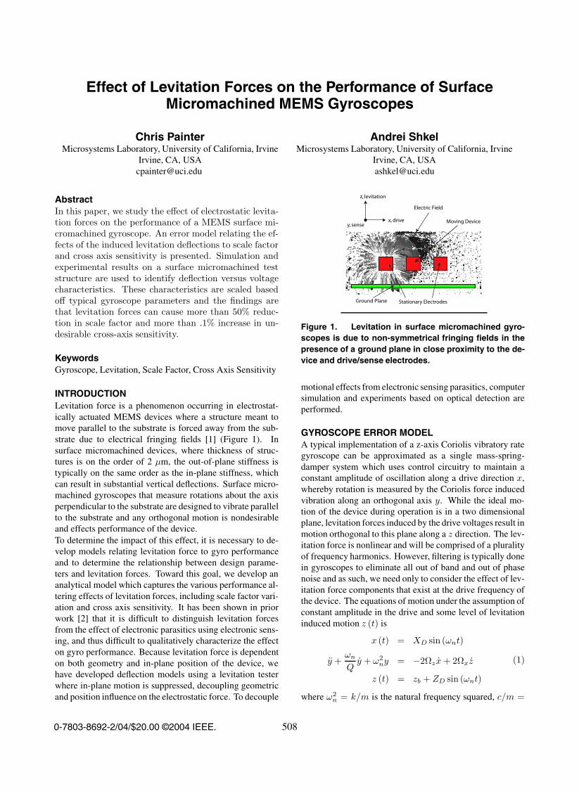
INTRODUCTIONLevitation force is a phenomenon occurring in electrostat-ically actuated MEMS devices where a structure meant tomove parallel to the substrate is forced away from the sub-strate due to electrical fringing fields [1] (Figure 1). Insurface micromachined devices, where thickness of struc-tures is on the order of 2 µm, the out-of-plane stiffness istypically on the same order as the in-plane stiffness, whichcan result in substantial vertical deflections. Surface micro-machined gyroscopes that measure rotations about the axisperpendicular to the substrate are designed to vibrate parallelto the substrate and any orthogonal motion is nondesirableand effects performance of the device.To determine the impact of this effect, it is necessary to de-velop models relating levitation force to gyro performanceand to determine the relationship between design parame-ters and levitation forces. Toward this goal, we develop ananalytical model which captures the various performance al-tering effects of levitation forces, including scale factor vari-ation and cross axis sensitivity. It has been shown in priorwork [2] that it is difficult to distinguish levitation forcesfrom the effect of electronic parasitics using electronic sens-ing, and thus difficult to qualitatively characterize the effecton gyro performance. Because levitation force is dependenton both geometry and in-plane position of the device, wehave developed deflection models using a levitation testerwhere in-plane motion is suppressed, decoupling geometricand position influence on the electrostatic force. To decouple
x, drive
z, levitation
y, sense
Ground Plane Stationary Electrodes
Moving Device
Electric Field
Figure 1. Levitation in surface micromachined gyro-scopes is due to non-symmetrical fringing fields in thepresence of a ground plane in close proximity to the de-vice and drive/sense electrodes.
motional effects from electronic sensing parasitics, computersimulation and experiments based on optical detection areperformed.
GYROSCOPE ERROR MODELA typical implementation of a z-axis Coriolis vibratory rategyroscope can be approximated as a single mass-spring-damper system which uses control circuitry to maintain aconstant amplitude of oscillation along a drive direction x,whereby rotation is measured by the Coriolis force inducedvibration along an orthogonal axis y. While the ideal mo-tion of the device during operation is in a two dimensionalplane, levitation forces induced by the drive voltages result inmotion orthogonal to this plane along a z direction. The lev-itation force is nonlinear and will be comprised of a pluralityof frequency harmonics. However, filtering is typically donein gyroscopes to eliminate all out of band and out of phasenoise and as such, we need only to consider the effect of lev-itation force components that exist at the drive frequency ofthe device. The equations of motion under the assumption ofconstant amplitude in the drive and some level of levitationinduced motion z (t) is
x (t) = XD sin (ωnt)
y +ωn
Qy + ω2
ny = −2Ωzx + 2Ωxz
z (t) = zb + ZD sin (ωnt)
(1)
where ω2n = k/m is the natural frequency squared, c/m =
0-7803-8692-2/04/$20.00 ©2004 IEEE. 508

(a)
VDCVDC
Fixed electrodesFixed electrodesMoving DeviceMoving Device
xx
zzyy
i1i1
i2i2
(b)
Figure 2. (a) The gyroscope sense electronics con-vert motional current into an output voltage based off (b)change in capacitance of the oscillating structure.
ωn/Q is the damping to mass ratio, Ω is a constant inputangular velocity, XD is the oscillation amplitude in the drivedirection, zb is static levitation due to DC bias applied be-tween the mass and electrodes, and ZD is the oscillatory zamplitude deflection component in band with the drive fre-quency. Based on the proposed mathematical model, thesense amplitude is solved to be
|y (t)| =2Q
ωn(ΩzXD − ΩxZD) (2)
The response from the gyroscope in the sense directioninduces a motional current which is converted to a voltageand differentially measured (Figure 2a). The magnitude isproportional to the capacitance values (Figure 2b), calculatedfrom instantaneous height z0−z, comb overlapx0, and combseparation y0 ± y
C1 =ε0x0 (z0 − z)
y0 − y
C2 =ε0x0 (z0 − z)
y0 + y
(3)
The output voltage is derived as
∆V =(
∂(C1 − C2)∂y
y +∂(C1 − C2)
∂zz
)RfVDC (4)
In gyroscopes, the sense deflection is typically small com-pared to the gap (y y0). Under this small deflection
SuspensionMass
Drive/Sense Electrodes x8
(a)
(b)
Figure 3. (a) The effect of levitation on a gyroscope isapproximated through experiments done on a (b) surfacemicromachined levitation tester which is compliant onlyin the out-of-plane direction
assumption, the output voltage is
|∆V | =4ε0x0 (z0 − z)
y20
QRfVDC (ΩzXD − ΩxZD) (5)
where the (z0 − z) term influences scale factor of the gyro-scope and ΩxZD represents the cross axis sensitivity. Sincethe static deflection is typically much larger than the verticaloscillation, z in the scale factor term is assumed approxi-mately equal to zb. Thus, for a typical gyroscope imple-mentation, we would expect a large variation in scale factorcompared to change in cross-axis sensitivity.
LEVITATION TESTERTo decouple the influence of in-plane motion on levitationforces, we fabricated a test structure (Figure 3b) which mim-ics the electrode structure of a typical gyroscope [3] (Figure3a), but has a set of four folded suspension members whichsuppress in-planex and ymotionwhile allowing out-of-planez motion. The device was fabricated using the MEMSCAPMUMPS surface micromachining process. The suspensionand mobile combs are made from polysilicon (POLY1 masklayer) with a thickness of two microns. A conductive groundplane made from .5 micron thick polysilicon (POLY0 masklayer) is spaced two microns from the bottom of the POLY1layer. The suspension beams have length of 200 micronsand width of two microns. The fixed drive electrodes are 3microns wide, the mobile electrodes are 4 microns wide, and
509

Fixed End
Mobile Combs
Fixed Combs
Ground Plane z
Figure 4. Multi-physics simulation of the levitationtester. Because of similarity conditions, one quadrantcan be modeled, reducing analysis time.
the spacing between the electrodes is 4 microns. Eachmobilecomb has a 48 µm engagement length with one fixed combon either side of the mobile comb. There are 14 engagementsper quadrant and 4 quadrants on the device.
FINITE ELEMENT MODELINGSimulations to characterize the levitation forces are per-formed using the Coventor multi-domain finite element soft-ware package. A reduced order model consisting of a singlequadrant of the device is used to lower computation time(Figure 4). In the quadrant model, a voltage is applied be-tween the mobile and fixed structure and the electrostaticforce is calculated at .1µm vertical translation steps of themobile combs. This process is repeated for voltage values of50, 70, and 100 V. The reaction forces are scaled by a factorof four, to account for the contribution of all four quadrants,and plotted as a function of vertical translation. The transla-tion is multiplied by the spring constant for the suspensionand also plotted as a function of vertical translation. Thefolded beam suspension is a well known type of suspensionwith a spring constant k of
k =4Ewt3
l3(6)
The equilibriumposition for a voltage is determined by the in-tersection of the suspension force and the electrostatic force.
EXPERIMENTS
Optical ProfilerometerTo verify the simulation results, experiments using opticaldetection were performed. The first experiment uses thePLµ non-contact profilerometer developed by Sensofar [4](Figure 5a). The levitation tester is first completely scannedto verify parallelism of the mirror with the substrate duringactuation. Any tilt of the entire chip is compensated using al-gorithms included in the software package. The cross sectionof one of the beams is scanned (Figure 5b) and the distancebetween the top of the Poly0 ground and the top of the Poly1beam is measured. The device is actuated using a DC powersupply for voltages of 0, 50, 70, and 100 V.
VibrometerThe second experiment is performed using a non-contactlaser Doppler vibrometer developed by Polytec PI [5] byscanning a single point on top of the device (Figure 5c). Asthe vibrometer was designed for frequency response, it wasnecessary to actuate the devices with a low frequncy (.1 Hz)sawtooth signal using maximum voltages of 50, 70, and 100V respectively and using the integration mode built into thehardware to integrate the output velocity. Figure 5d showsthe 50V sweep, which will be used to derive the deflectionversus voltage fit in the next section.
RESULTSThere is good agreement between the simulation and theexperimental results (Table 1). We derived the relationshipbetween the actual gyroscope (Figure 3a) and the levitationtester (Figure 3b). The gyroscope uses approximately eighttimes the number of combs for drive and sense. The gyro-scope has an out of plane stiffness of .3 N/m whereas thetester has an out-of-plane stiffness of 1.5 N/m. A fit to thedata in Figure 5d gives the relationship
400δ3t − 600δ2
t + 800δt = V 2 (7)
where subscript t denotes tester related parameter and g de-notes gyro related parameter. Eq. 7 yields only one realsolution for the tester deflection δt. Using Ft = ktδt andFg = NFt, we can transform this equation into a more gen-eral equation that can be applied to a device with similarelectrode geometry, but with N times the number of elec-trodes and a different out-of-plane stiffness
V 2 = a1
(kg
Nδg
)3
+ a2
(kg
Nδg
)2
+ a3
(kg
Nδg
)(8)
where a1 = 118.5, a2 = -266.7, and a3 = 533.33. Here, Nis a scale number of combs compared to the tester and kg isthe out-of-plane stiffness of the gyroscope. For the consid-ered gyroscope design, the static vertical deflection is 1.28µm for a typical bias voltage of 5 V. This is comparable toresults presented in [1], where resonators of one eighth ofthe gyroscope size were shown to have deflections of up to 2µm with 25 V bias. From Eq. 5, the resulting loss in scalefactor is estimated to be 64%!For the small dynamic oscillation about the static equi-librium, we use a transfer function of linearized parame-ters. The driving voltage is typically of the form V 2 =(VDC + VAC)2, where the AC frequency is the in-plane nat-ural frequency ωn of the device. The only surviving infrequency band component of the electrostatic force is pro-portional to 2VDCVAC . Thus, the linearized transfer functioncan be presented as
∆δ (s)∆VAC (s)
=φVDC
s2 +ωz
Qs + ω2
z
(9)
where ωz is the out-of-plane natural frequency and φ is anunknown constant function. Linearization of Eq. 8 about
510

Scan location
Top of Poly0 Top of Poly1
(a) (b)
4 5 6 7 8 9 10 11 12 13
0
1
2
Deflection and Swept Voltage versus Time
Time (sec.)D
eflection (
um
)4 5 6 7 8 9 10 11 12 13
-20
0
20
40
60
Voltage (
V)
Deflection
Voltage
(c) (d)
Figure 5. (a) Device is first tested using an optical profilerometer by scanning a (b) cross section of of the device’sbeams under varying voltages. (c) The second experiment is under a vibrometer which scans the device at a singlepoint. (d) The device is swept under a low frequency voltage signal, giving the deflection versus voltage profile.
Table 1. Comparison of deflection values
Voltage Simulation Confocal Mic. Vibrometer50 V 1.7 µm 1.6 µm 2.0 µm70 V 2.2 µm 2.0 µm 2.4 µm100 V 2.7 µm 2.3 µm 2.7 µm
the equilibrium deflection and voltage results in ∆δ = .52∆VAC . Substituting this into Eq. 9 with s = 0, correspond-ing to a low frequency response, gives the value for φ. Thegyroscope has an out-of-plane frequency of ωz = 4000 Hz,an in-plane drive frequency of ωn = 20000 Hz, out-of-planeQ factor in vacuum of 1000, and uses an AC drive voltageof amplitude .25V. Solving for oscillation magnitude givesa value of .005 µm, a negligibly small amount in this case.Since this gyroscope operates with nonlinear parallel platesand is limited to a drive oscillation amplitude of .67 µm,the cross axis sensitivity is .7% of the main axis sensitiv-ity. This small value of cross axis sensitivity is due to thelarge frequency split between operational and out-of-planefrequencies. For example, for a device with a 15000 Hz out-of-plane frequency, the cross axis sensitivity would increaseto 25%.
CONCLUSIONSWe have derived a model which relates the effects of levita-tion forces to scale factor variation and cross axis sensitivity.Through simulation and experimental verification of a levita-
tion tester, it was shown that levitation forces can have a sig-nificant effect on the performance of surface micromachinedgyroscopes. The results of the simulation and experimentswere applied to a typical example of a surface microma-chined gyroscope which show levitation forces causing a64% change in scale factor and introduce a .7% cross axissensitivity. Compensation strategies [1] are necessary toreduce these effects in order to achieve high grade inertialsensors.
ACKNOWLEDGEMENTSThis work is supported in part by the National Science Foun-dation Grant CMS-0409923, program managers Dr. Shih-Chi Liu and Dr. Masayoshi Tomizuka.
REFERENCES[1] W. C. Tang, M. G. Lim, and R. T. Howe, “Electrostatic
comb drive levitation and control method,” Journal ofMicroelectromechanical Systems, vol. 1, no. 4, pp.170–178, December 1992.
[2] W. Geiger, B. Folkmer, U. Sobe, H. Sandmaier, and W.Lang, “New designs of micromachined vibrating rategyroscopes with decoupled oscillation modes,” Sensorsand Actuators A, vol. 66, pp. 118–124, April 1998.
[3] A. Shkel and R. T. Howe, “Micro-machinedangle-measuring gyroscope,” November 2002, U.S.Patent 6,481,285.
[4] http://www.sensofar.com.[5] http://www.polytecpi.com.
511