Embed Size (px)
Citation preview

"U.S. DEPARTMENT OF COMMERCENational Technical Information Service
AD-A031 590
EFFECT OF MULTIPATH ON THE HEIGHT-FINDINGCAPABILITY OF FIXED-REFLECTOR RADAR SYSTEMSPART 2. APPLICATION TO AN AIR SEARCH
RADAR SYSTEM
ROME AIR DEVELOPMENT CENTER,
GRIFFISS AIR FORCE BASE, NFW YORK
JULY 1976

13114
Effect of Multipath on the Height-FindingCapability of Fixed-Reflector Radar SystemsParm3 ctlon to an Air Search Radar System
-ONALD L FANTEPE11 IL FRANORICHARD L TAYLOR
DDCNOV 3 19,'6
ROME AIR DEVELOPMENT CENTERAIR FORCE SYSTEMS COMMANDGRIFFISS AIR FORCE BASE, NEW YORK 13441
NATIONAl TECHNICAL!N(FOPAAATION S-ERVICE
'A. w 14 I'

PUBLICATION REVIEW
This report has been reviewed by the RADC Information Office (01)
and is releasable to the National Technical Information Service (NTIS).
At NTIS it will be releasable to the general public, including foreign
nations.
APPROVED:
WALTER ROTMAN, Chief
Microwave Detection Technique , Br.
APPROVED: 4WA/
WALTER ROTMAN, Acting Chief
Electror-agnetic Sciences Division
I= lu ,' or u U
gmavolU,311ma1 CODlE,
AWL FOR THE COMMANDER:
1 Plans Office
U~n'lagsgi fledSECURITY CLASS'rlICATION Or THjq o-ASE~fln ~r.td
RF$ P' V STPUCT'ý)'%SREPORT DOCUMENTATION PAGE BEFGkRE COMIPLETING FORMIf.REPORT NU.UMEn 12. GOVT AC('rS?16CN NO. 1. PF.CI ''_WF CA~- RUg'.!q
RADC-TR -76-2154. TTLE u~d ~bI~I,)5. TNFE 3; REPGk7 A PERIOD COVEREZ
EFFECT OF MULTIPATH ON THE HEIGHT- nHueFINDING CAPABILITY OF FIXED-REFLECTOR InHueRADAR SYSTEMS, PART 2: APPLICATION TO 6PEWR0OHMING ORG. REPORT NUMBERAN ATE SEARC1 RlADAR SYXIET..
7. AUTHOR(.) S. C0N1r.ACTOQ~GRANT NUmBEr;W) -
Ronald L. F antePeter R. FranchiRichard L. Taylor ______
9. PER'rORMING ORGANIZATION NAME AND ADDRESS IC 'ILPV-TL4E~.PR~jEC T TALD~eputy for Electronic Technology (RADC/ETEP) K~R JNIT NUMBERS
Hanscomn AFB, 6110 FM~'assachusetts 01731 2 1530201
11. CONTROLLING OFFICE NAME ANO AOD14ESS It. REPORT 0OA C
Deputy for Electronic Technology (RADC/ETEP) July 1976Hanscomn AFB. '?I NJ4§i~ri AiOES
Massachusetts 0,1731 21___It hAO"ITQING AGENCY NAI*9 a ADORLS5wif Uje... #~No cepowUips O4(ce) M5 SECURITY CLAWS (Q# Ithis Pogo")
Unclassified
S.W COULE
Approved for public release; distribution unlimilted.
'7 wtmuU.o.4IOANdNY to# so 44t e *u.a#"" k s A woo it ~k~h#M# 6" 6
lRefector ante~nnas
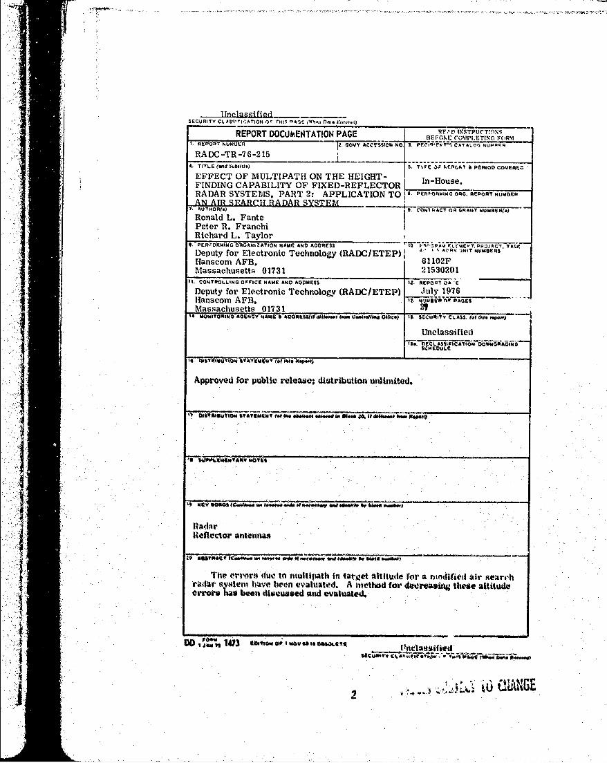
The ort-or's due to niultipath in tairgot altitusteror a niejdIisetl air gearchrAdlf Sst*~em Wivo twoin evalustod. A nwithad for deereasbtg, these attitudeerror* has been discussedA and evaluated.
DD,00 1473 t~utow "v' *a t oes"ItUIwi? IV '~ #ýR i 4;ri Alt
jIuMNC

U~nclassifiediSECURITY CLASSIFICATION OF THIS PAGE(RIm Data Ent.,.d)

Contents
1. INTRODUCTION 7
2. THEORETICAL REVIEW 7
3, SINGLE-HIT ERRORS i1
4. MULTIPLE-lilT ERRORS 18
5. CONCLUSIONS 20APPENDIX A: Element Pattern 21
APPENDIX 1: Radiation Patterns for Various Types andSo.ations of the Secondary Horm 23
APP.NDL)X C: Altitude Error Plots 25
Illustrations
1. Modification of -lh-tor Amtenna so as to Oxtain,
Altitude hifornAttion 82. -O.metry Of tho I)iect Aand hlultipmh I.Wks
3. taxiimmu Altitude Error ltiefloctor Eevution, d 0.05 milef;%nd Target tiange. It q 50 miles 13
4. ,Maximrum Altitudo Error for lteflor l.h...ation. d o 0. G5 mtlesand Target flange. it 100 miles 13
3

Illustrations
5. Maximum Altitude Error for Reflector Elevation, d = 0. 05 Milesand Target Range, R = 150 Miles 14
6. Maximum Altitude Error for Reflector Elevation. d = 0. 05 Milesand Target Range, R = 200 Miles 14
7. Phase Angle of the Radiation Field for the Primary Horn (6^) andthe Secondary Horn (01) for the Conditions of Case 1) of Tiable 1 15
8. Effects of Using the Incorrect Assumption 61 = 62 on the MaximumAltitude Error for the Reflector of Case A (Table 1) andR = 100 Miles, d = 0. 05 Miles 16
9. Effect of Using the Incorrect Assumption Ll = eb on the MaximumAltitude Error for tue Reflector of Case A (?able 1) andR= 150 Miles, d= 0.05 Miles 16
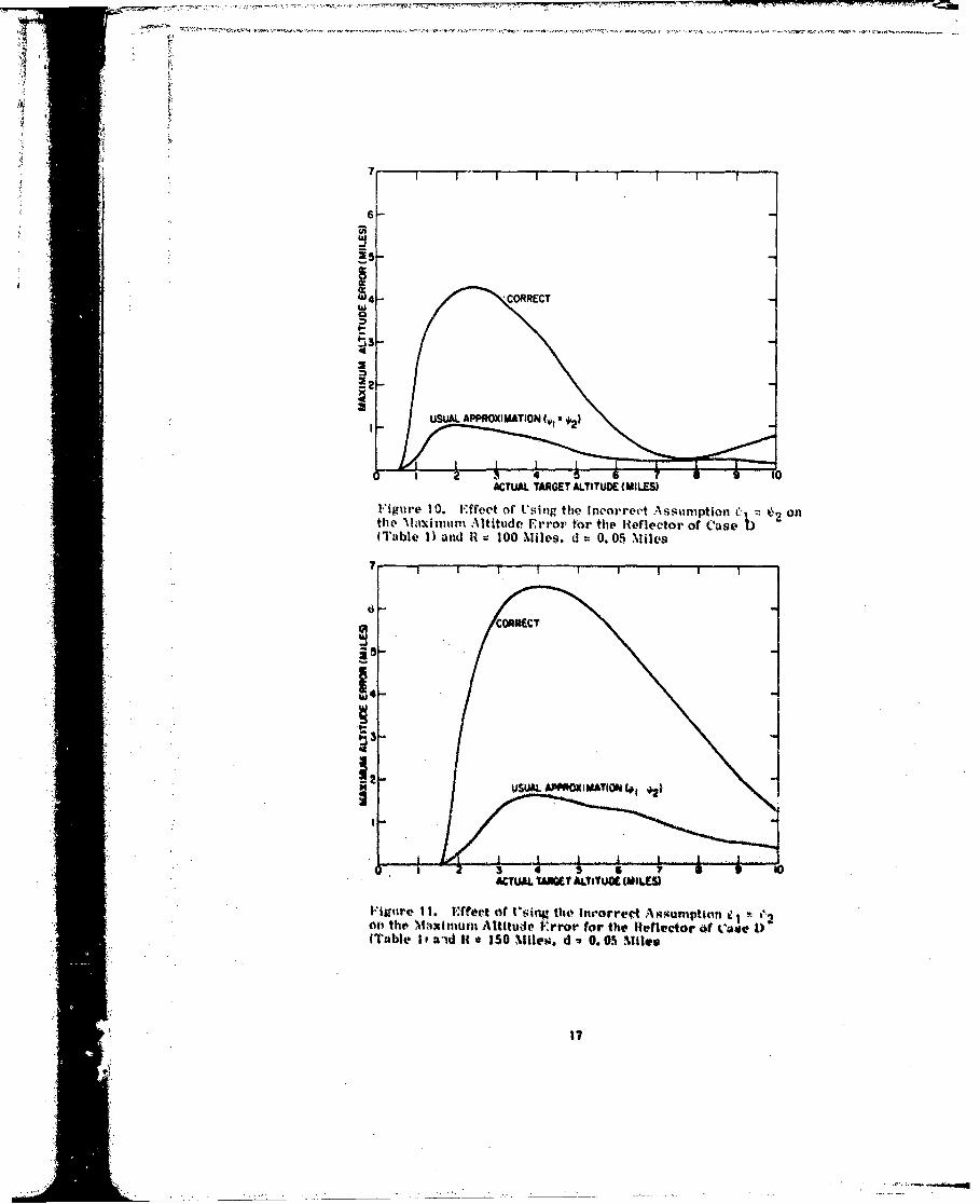
10. Effect of Using the Incorrect \ssumption L' -2 on the NMaximumAltitude Error for the Reflector of Case 1) (Table 1) andR - 100 Miles. d = 0. 05 Miles 17
11. Effect of Using the Incorrect Assumption 61 = 0 on the MaximumAltitude Error for the lefh, ctor of Case D (I able 1) andR = 150 Miles, d= 0.05 Miles 17
12. Effect of Averaging on the Maximum .\ltitude Error for a TargetFlying at 3 Miles Altitude, for Case C of Table 1 19
13. Effect of Averaging on the .Maximum .\1tltudf. Error for a TargetFlying at 6 Miles Altitude, for Caqe C of Table 1 20
AI. Radiation Pattern for the Reflector for the Case When the PhrlmaryHorn is Located at x = _34. 0. y: 0 . , L 202.1131) 92
B1. Radiation Pattern When the ,erondar% llor,p ks , %oeat,,d at x1 51. 47".201. 15" and Ita F(L) ; I - 4.921) (detiontod by Case A
in Table 1) 24
B2. Radiation Pattorn Whetn the Secontllov isrt at xt t St.a 200. " and has 1 expa-l. 0509). (dlnoted by Ca.e B
133. Ratdiation Pattern WVton tho Seeottondn 1or Lovated at X,-51.470s?lcv 201. 15' wid hus F'e,') expt -Ia. Oi60h (denoted 1w as C
It Ta ble 1) 24144. Radiatition Pattern When the Secondary Itorn it lorated it 5 • "5.•"34
200. ,50" anad hu. FVIC,) r 1. 0 idenotod by Case 1) itt 4 abhe I) 24Cli. Altitudte Error (miles) vs Altitude (miles) for a Ttirget Iange of
100 Mites 26C2. Altitude l-'irro" (miles) v, Altitude (ntles) for 100 Mile Target 1% ItC3. Altitude Error (miles) vs Altittide (mileo-) for 150 Mite Ta.rget RWange
(4. Altitude Error (miles) vo Altitude (miles) for 1S0 X1. Targriert Mango 26CS. Altitude t*etror (miles) vs Rlange (ntiles) for a Tor'et Altitude of
3 Miles and flefletor lklevation d n 0. 0t lihs ( 02)
CG. Altitude Error (miles) vs NRange (miles) for a Target Altitude of6 MIles and a Reflector 1,:levation d z, 0. 01 Miles (52') Assumingthe Reflector Systean of Case C in T1able 1 2
4

Illustrations
C7. Altitude Error (miles) vs Range (miles) for a Target Altitude of3 Miles and a Reflector Elevation d = 0. 76 Miles (4000'),Assuming the Reflector System of Case C in Table 1 27
C8. Altitude Error (miles) vs Range (miles) for a Target Altitude of6 Miles and a Reflector Elevation d = 0. 76 Miles (4000'). 3Assuming the Reflector System of Case C in Table 1 27
Tables
1. Location and Pattern of the Secondary Horn 12
2. Relationship Between Altitude H and 0 for a SphericalEarth, and d 0. 05 Miles 15
S.

Effect of Multipath on the Height-FindingCapability of Fixed-Reflector Radar Systems
Part 2: Application to an Air Search Radar System
i. INTROUKiTION
In Part I of this report we developed the theory necessary rat, determining theerror (due to multipath) ln the altitude meksrin• vapability of a reflector radarwhich Is modified so afi to operate In a monopulse mode. li this portion we willpresent detailed calculations specifically for an air search radar system, whichWs modified by adding a second feod horn, and then operated as a monopulse 14s-tom. as is indicated In Figure 1.
2. Tlt•UF1TICAL REVI;EW
Boftore gzoing on to present results rot, the altitude orrors due to multipath. weWhall first disruss the operation of the modifitd air -Aearch radar when multipathIU absent. Let Als co.onsider thle reflector it, iI•itir I asd atsttne that i, tile ab.senceof multipath thie far-fihld pattern duh to the primary horn tA toW) exp 0i to()whore 0 I1 the elevation angle and (OM) ts real. Also assume that hi the absene .fmultipath the far-tield pattern dtte to Aecondary horn is (M) esp I1 01() 1 • 1he1the output voltage of the Iow amplifiters in Figure I is
(l~eceived for publication 16 July 10761
F-1
Frcd iln

SýPMRJI AIRY~. HRN (X0,?0)
REFLECTOR W--,- SECONDARY
'Rlog
logamp amp
+
v
I~tjA~t(~ . M~iit'~tof f a Reflector Antenna -4o Us toUbtato Altitude Information
V K log 10- K logtW t~d) (I
wnere K to a vonitlant and
Then. negleding 44y~tem tnoij~e, we gi- that thio target elevation angle i s
10()
wherp V ' %.4 the~ Itivere of lthe runction F~.
we !%~ve ealruloteill the vavn radiation pAtterolI onW for Iliv air
seareh radar Aytei The rellultU Of Our ettlcultiotath are pi'esmnted in A~petldfu A;

I:
we show there that our computer calculations for the radiation pattern are in
excellent agreement with the pattern measured using the actual air search reflec-
tor bystem. We have also performed calculations of the vacuum radiation pattern2N| _ [fl(0) when only the secondary horn is excited. These results are pre-
sented in Appendix B for a number of different locations and types of secondary
horn.
Next let us consider the effect of multipath on our ability to measure the target
elevation 0. It we refer to Figure 2 we see that the far field at the target (when
multipath is included) due to the primary horn only is
E0 fofa(0) e + p Df 0 (4 exp i i0o(-) + i k AR (3)
where AR is the path difference between the direct and multipath ray, k is the sig-
nal wavenumber (2-a /), p is the reflection coefficient of the earth at the reflection
point, and D As the spherical-varth dispersion factor, The field at the target due
to the secondary horn is
W01(0) 1V, fl(0) e * p tU -) exp i 0 (4") + i kkR * (4)
hgure 2. Ueometry of the Direct t•id MIultipath Lit"k
By u4Ing Vqsto. (C) and (4) z|oton with 1t t re I It Is clea#4t1at w Mtt I mu1tpaith it tn-
cluded the output voltar VN of tUw log-amn• In Plgwe I s
,ii

E1V M =K log1 0 o
2
+Kog0 f 1(-0") i! Of
~(0 1 (-pk D f (0U)k0 og 0 0 ol 5
Upono foprn (-a") (5 n ()w set
0~ ~ ~ p 0 (-') -0 + All)
+V AV~1 W00
It is intotep#ting to note from k.o. (7) thnt it the refloctor doign had horn loomionit
are Stich thait k i and
f~ ~ M)i'
01

The error voitage given by Eq. (7) can be readily used to deduce an equivalent
error in target altitude H. This error AH is
A-il- ( VV 0o- H
where in Eq. (9) we replace 0 and 0" by their definitions in terms of I1. These
are given by Eqs. (62) and (36) in Part 1 of this study.
We have now completed our theoretical review, and can begin to study some
results computed using Eqs. (7) and (9) for the altitude error of a modified reflec-
tor. We mill first consider only the error in altitude deduced on the basis of a
single radar "hit", and will later consider the improvement (dec-ease in altitude
error) which occurs when the altitudes deduced on multiple radar hits are avenelud.
I . :;rIulE.IrI" ERRORLS
ln this seetion. we will present results for the alitude er lit"n th. trut t'altitude dedutced from it sinlgle ra•'darl llt forl at modified raidar sv~ttvl'l. \,4 dis4-
cussed previously, we are eonsideirnu an antenn that is nmodlifitd by adding a
second horn in the focal reioln, as iidicated Il Figure 1. \Xe Ohal! prs.ntit rr-
sutlts for faur different cases for tVie eovoilary horn pttertl andl lovatioll. Th'se,
are tabulated in Table 1. Tie function 1,i s the radiation pattern ofi the stetmd-
nry horn In the N-y plane. where gz It 1) Is its pattern in tht, e-a plane iv is normal
to thet plan• in Figetir 1). The altitude error vs actual targret altitude fr ft ind
?anlpi for several of the cases tAbulated in T;.ble,14 1 art, promente-dlit i1 rl1i.rrs (Ato C(4 In Appendix (. \k!p Wentet th4t the !rror isitt fin Attril rf'.u fli otaf r
altitude. The smeI tlraUse of the pldot of ia-rgrt altittue ert'mt vs target i-'b;e•
(tot' forAM target alt~tudel shown in lig.rme CS to CA in .ppwndsx Q.
In thin e.otion e pri'sent the •tivelo"pr, of tme run1 tr•.n kt,-•Nt•1. in O lgr,, VI
to C4, and t Ill label thlese envolopsA .i itt "oiaxt•tii altitikth, error'". "l'h'
ressults. for' the cases lis.ted in Table 1. *r ai prsented in I'igurt"* 'T tk 6. \lth%*iwgwo h1mv preseniter-d tho mIaximum1 error in turet "altitud,. Ap ( FtItrlistn lf -itIMUM
target altitudei It. one coold Also relate the vrror to the ton angle.. Oi. by re-
fewring to TaPle 2. Tlhre ire :a numlbr of obmn'rmatio we shouald ,. . reIgdnu
the resunlts phrm•ltid in Figturesf . Io G. I'lltble airet:
Wle hive -'ctu:41|1 .0llotdid glnit% "iloe than f012V e;ase's, but forii efld'5' .t-' wiltprosent only thost vwhici art. typil.•.
tII
. 4 K > : >fi->"- ~ -..- &

(a) The sharp peaks in altitude error in Figure 3 occur where d V /d H Z0.0This means. that even -.n the absence of multipath there is likely to be a large
error in target altitude (due to system noise).
(b) Thle worst altitude error (excluding those cases when d V /dMH =0) occurs
when the elevation angle 0 is about 0.60. This point canl be seen using Table 2 to
relate the target altitude to 0.* (c) The location and radiation pattern of the secondary horn can have a very
significant effect on th~e ir nitude of the maximum altitude error.
(d) The results hin res 3 to 6 are rather insensitive to the height d of the
reflector above the g' - Calculations for d =0. 01 miles and d = 0. 03 miles
gave substantially thle ame results as for d = 0. 05 miles. except very near to the
horizon.
Table 1. Location and Pattern of the Secondary Horn
LI~~~8 ,. 1hn. I~I~ 1_______________-51.47 201. 15 1-'l. 941, r ~ exp-
14 - 57.43 '20 0. 3 2 ep-11 W2-.47 201. 15
-5 LI 2:4 100.5109 1.0
hI addition to the aforeluviiotlned, there it; another 1xiint whieh requires further
dth-ailed Vollment. 1*he Case abireled I) it, rawt. i anti rigures ,i to Ii iq one, for
101i,1 tho pri mo IY and soetlarv. radialOtn WitternS4 verv neArlY fulfill the reqaiirls-
tilelt v'ilres-ted hn Pq. (M1. 'ThW van bie seen li v otmariqj Figure A 1 Inl Appwndi
A With Fi~gure Its ill Appenldix ji. Th~r'etore whv i,4 the altitude error ta largze" Tile
miswer is that the phame tý 0 t0i1. t I0 - k &H4 doesl not eqttal k% r o (-a*)10 0
- 0(0 k~H.~ at aip, oftepaeugligi't 10 1 of tho prlimary horil With
of( tile evvonidru horhn is shownj in Figltv ro. PoeatIso 0 (13 1 4Ill 01101 e rirelusitilo, Votitantit, Ior jlinear, fttvl-ijign Of 0 Withl thi sa Ag lepe 4104 It is rlear that
01 -1- 11cnOtqual v.l t0) onseqwentlY C ~i e 'fiitaey
1111151 malvgeA of fiottopulse reflecor sygtions neglect1 the plihse disatribution of tite
rmdinted filOO, If the, phsise hapwens, to 1w nearl~y litlear ovelr the ratigo of 0 of
In~terest tfis may not lWad to inteorreet results, but tit getlepal it does lead to Ineor-
rect resul11ts, Ill 1Fiures, R wo 11 We have vomtul~rtd tile 1re911sul for thei altitilde
error "tife Would obtainl hby.A .qIs~tIg 0ý I~ -, V with the( cotrvect Pe.-mlts. V'or tilt cggo
l0441%d Itit In Thtle I thIgs mAoxmption dors4 not lead to radical differotnces. bec-e~.s
thle radinfflo ;uttevig do not %atiqf the roquiremenit e3nvsse-4d by t'. (3). but fot-
Case 1) it is clear that the ewronpoieo acloutilption tll;t 0;a leads4 to Completely

spurious results. Therefore the phase distribution of the radiated fields must
be accurately included in any evaluation of a monopulse reflector system. Of
course, we have included the phase angles 0o(0) and 01(0) in all of our calcula-
tions.
2 ,,[C!
S= iiA
I' __________J_____
o_ 1 2 6 T' a 9 toCTUA,ý TARGET ALTITUDE (MILES)
1i'ture 3. Maui Altitude Irror far iRefleetor IElevatton.d 0. 05 miles and Target ItRnge, It a 50 miles
I j
F'igure 4. N.,-ixinm Al \titude K'rror for tenleetar i,.ievatian.0 . 05 mi les and Ta. ret Ha %tpe. It 1•00 milo *1
13

Ty 87
6
W4-
4C
ACTUAL TARGET ALTITUDE (MILES)
F igure 5. Maximum Altitude Error for RelcOrFevation,d 0. 05 miles and Target Range. R 150 miles
IA
14-
ACTUAL YTWA T ALnTiUDE (Mi LES)
I. igtutC 6. Maximumt- Altitudo Vrror for ~Wtflor 1h'evalion.d 0.05S minimo and Target Hatw~. 11 a 200 milv*;
14

Table 2. Relationship Between Altitude H and e for a Spherical Earth, andd = 0. 05 Miles
r = 200 miles K 150 miles R = 100 miles R = 50 miles11 (miles) 0 :degrees) 0 (degrees) 0 (degrees) 0 (degrees)
10 1.76 2.98 5.13 10.97
9 1.47 2.60 4.57 9.87
8 1.19 2.22 4.00 8.76
7 0.90 1.84 3.43 7.64
6 0.62 1.46 2.86 6.51
5 0.33 1.08 2.229 5.38
4 0.046 0. 69 1.72 4.24
3 -0.240 0.31 1.15 3.10
2 below horizon -0. 069 0. 57 1.96
1 below horizon 0. 0017 0. 82
0.5 below horizon 0.244
560
/
/
/I
- .4 .4 .2 0 2 4 6 U toELEVAt•ION M (ID0EGUES)
L I I 'vi r . i7 P ý•v * -\111. i, f ti he t 0, 1.i.•ttntt v.ivid for the Ptimt atrytloeti It)") Mini thle 'ý,roiitdrv Htorn 0Ilt for 0h10 Condtittvn of-'t~' i) t T~ih I

6-
w4t i.*-,CORRECT
4
USALT~~TRE LTTC ML
14 4
ACTUL TARGET ALTITUOE (MILES)
Figue 81. Effrect of Usling the Incorrect Assurnption &1 othe Nlaxinuni Altitude E~rror for the Reflecto~r o~f C~ase A(Table 1) and It 100 miles, d 0. 05 muiles
6-6
r'" I I I I I I I I
6
4-
USUAL APPROXIMATION j,, •2
ACTUAL TARGET ALTITUDE (M~IL.ES)
Fig"•re 10. rffect of Using the Incorreet Asstmption 02 onthe Ma,•idnum Altittide Error tfr the Reflector of Case(Table 1) and It 100 Miles. d 0.05 .Miles
T I I t
2 3 4 5 6ACrUAl. WayT ALTITUOE (MILLS)
"igutre I1. ifteet Of t'Vingl thO' lnrorrert A .4umption e 0,2(ts the MNiximunt Attitude Frror for th'leflt'ector of Cave D.)(Tablto It awd It e 150 ,ller. d a 0. 05 Miile
17

: i~
4. MUII'IPIE.--IT ERIL01S
Since the altitude errors for the modified radar system are reasonably large,
as is clear from Figures 3 to 6, we inquire whether there is some way of proces-
sing the radar return so as to lessen the error in target altitude. One technique
comes to mind when we observe Figures C5 to C8 in Appendix C. We observe that
the altitude error is an oscillatory function of target range R. Consequently, ifwe sampled the error curve at a number of sufficiently widely spaced parts we
would expect to reduce the error in our estimate of target altitude. The radar
system scans at a rate such that there are six target hits per minute. For a tar-
get approaching the radar at 600 mph this means that there will be six hits for
every ten miles of range covered by the target. We now suppose that the radar
system estimates the target altitude on each of the six successive hits, and then
averages these six values. l)oew this lead to a better estimate of true target
altitude" The answer is Yes.' This can easily be seen bY sampling the altitude
error in Figurer ('5 of Appendix (C at 6 equall'y spawed points teach point is 1.67
miles in range apartl. Note that for somt, samples the altitude error is positive
whereas for o•iers it is negative. .o that we expect that the altitude errors will
decrease when we average in this f;tshion.
In order to he quaintitative, let us conisider six .(t-,;.sive radar hits heginning
at time t Ifor a target appr wihing at 600 nhIVs p01r houtr eatch hit will be 1.670
miles In rt'anPa 'kiirtl 3Md let us :,ssllni. thait thilt- 2itude error tinl teah of these hits
0a a lI~ii 4 K . 61. 1*th en1 tile average altittide error derived by avelraging these 1i hits
it;6
All it IAllI . (101
Ilowever, the s.trting time t 0 of our 6 pulkte averaige v;a N' ., hitrarv o0e rmust
ulso avrage over t* o denote' tho4 ;1verge1wv li , If-%. 410 this4 is thle average1lltittde error %t , are likely to hav. when we safttmate the' targ~et altitude on the
WaSWI of A siox. hit aver-ie. t'fortunatel- it is nut steffieleit to ronptpte 14itnplV
the average nltitude error e A I1ý . herinui,• for •otfltions •uelh a%; Rhown in FtguresCo and VI8 In Appendix C. tl'e aivertae altih-de error - a 1I1 is tunerlv Pero. whert•-
as4 a vingle simple averagte A lilt 0 rmulht differ greatly fron' i-two. de'ietditg oi
thle Initi-al Ntart to of the average. Tt,'hro(ore It •s also neeessary to eompute the
gtandard devintion of our aver•ge. & Ii it 0 . Tlhiis t4 given by
I- 2

I
where < > denotes an average over the initial time to* We can now define a
maximum likely altitude error ( H as
CH = [<AH>I + 2a (12)
This means tchat when we estimate the altitude by a 6 hit average as indicated in
Eq. (10). tVaere is only a 4 percent chance that the error will exceed ElH' In Fig-
ures 12 and 13 we have plotted this maximum likely error along with the error one
would obtain on the basis of a single hit (no averaging). The values of ý H have been
denoted by "averaged", and these have been plotted for three different reflector
elevations, d = 0. 01 mile, d = 0.03 mile and d = 0.77 mile. From Figures 12 and
13 we note that averaging leads to significant reductions in altitude error, and
consequently a much more accurate estimate of the actual altitude of the target.
SNO AVERA41N
41I AVIE0AM14'00S3 AVER*AGD EdvO
fMT ANGL (IMLES-1
llgure 12. l'ffect of Averaging on the Maximum Altitid#' Crrorfor a Turget Flying at 3 Miles Altitude. for Case C of "table I
10'

6-
5 -
64 - '-
X AVN G£ d OT? AVERAGING......•l ,.,.•,...
n
22-
AVERAGED (d ,0.0)
U ~AVERAGED Wd077)
U k~'m /| :I jAVERAGEDW(d-003iW900 120 140 160 180 200
TARGET RANGE (MILES)
Figure 13. Effect of Averaging on the Maximum Altitude Errorfor a Target Flying at 6 Miles Altitude. for Case C of Table 1
S. (:u0NCLU.1;jWS
(a) The radiation pattern and location of the secondary feed horn, can have a
significant effect on the altitude error (due to multipath) of the modified radar.
(b) One must be careful to properly include the reflector phase distribution.,
M(O). in evaluattng the alttitude error due to multipath.
(c) The error in altitude, or deduced on the basis of a sitgle radar hit, can
be reduced by .a factor of 2 or more by averaging over a number of hits.
20

Appendix A
Elenmt Pattern
\e study here the radiation pattern of the reflector when fed by a single
(priniary) horn located in the focal region. This is the normal (non-mo0nopulse,
operating mode of the radar. We shall also assumv here that the earth is absent.
so that we will study the radkitton pattern in the absenee "of multipath.
We have shown that the reflector of the tiir search radar can be modelled by
the approximate analytical formn (Net Figure All.
1 2 Ix) y 4 - 35. 161 (Al)
00erT x. v. o are measured in inches and M(x), 0 (x), -nd T(x) are given elsewhere.
The eoordinate v 1x) describing the projetilon of the hotindary of the dish (see E~q.
(79) in Part 1) onto the it v 0 plaae is given elgpý%a.re. The radiation pattern
(Wee Part 1) of the feed horn can be approximated by
2 4
I - 4. 02 •, S. .1-0 (A -2)
010i )r exp - 1. 64414go (A3)
where i •s the angle (in radiang) measured in the x" •' plane In Figure 3 of Part 1.
'Ind It Is the angle in radiats in the y' - a' plane. The location of the primary
toed horn is taken to th x -" 34. 0 in. yo It 0. and *o " 202. 113.) in. and the assumed
frequency of operation is 1350 Mlit:. A comparison of our theoretical radiation
21

pattern (obtained by using Eqs. (Al) to (A3) in Eq. (84) of Part 1) with experiment-
al data is shown in Figure Al. It is quite evident that the agreement is excellent.
30
Z 01 0
Figure Al. Radiation Pattern for theReflector for the Case When the PrimaryHorn is Located at xO = 34. 0, yo z 0.
3o = 202. 839. It is assumed that thesecondary horn and the earth are absent.Computed results are indicated by thesolid line and experimental values by (0
23

Appendix B
Radiation Patterns for Various Types and Locationsof the Secondary Horn
i Figurse HI through B4 we -.how the rutcation outterni of the air Seareh
radar (with the earth absent)• 'hen only the Reeondary hornt itpO,
23

I7-FR Mm ! pII
3 30
~_ 20 /
0 0t -101
-324 .. ~~~30~ -------
Figure 131. Radiation Pattern When Figure B3. Radiation Pattern Whenthe Secondary Horn is Located at the Secondary Horn is Located at
51.47"z 201. 15" and~ had x 5 1. 47 ". z = 201. 15' and has
by +as A. i24 4al ~. (denoted Fb)=exp(-18. 05tb 12), (denoted byby &s A i Tabe 1)Case C in Table 1)
... . .. . -- ---- - -
IJ lIv , 01 .ntdb c"1 i
px"( ..4 050 12) 40%tý
Case N in TAbk 1) Ta~ble 11
24
Iv

Appendix C
Altitude Errot Plots
In Figures C 1 and C2 we show the computed altitude. error vs target altitude
for different secondary horn locations when the target range is' 100 miles, In
Figures C3 and C4 we show the computed attitude error vs tat-get alttitude wheon the
range i 150 mildes. Figures (C5 to C8 show the altitude error vs range when the
target Mlitt at a tonstant alttitude, for .several differont radar dish elovatins,. In
al• tof these results Wc. have con•sdered only ipecular refleetions from the oarth'sSurfae~.
25

ýfl I 1,A 1P A )i I 14 ' ,-
- '. 8
H
F igure C1. Altitude Error (miles) vs Figure C3. Altitude Error (miles) vsAltitude (miles) for a Target Range of Altitude (miles) for 150 Mile Target100 Miles. Also. d = 0. 05 miles and Range. Also. d = 0. 05 miles andthe reflector system is given by Case A reflector system is given by Case Ain Table 1 in Table I
41 MR 4 ý..I.
Figure C2. Attitude V. Frr(io)~ iagure V4. Attitude lError frailest vsAttitudes (miles) for 100 'Mile Target Attitude (miles) for 150 Mile ThrgetRange. Alwo. d!ý 0 05 midles and Itunge. Alito. d 0. 05 minle# andrefloctor system is given bky cut* l~ refle~ctor systemi is given bky Cast H,in T~able I in Table I

II
-2'-i-4 -'L
RANGE RANGE
Figure C5. Altitude Error (miles) vs Figure C7. Altitude Error (miles) vsRange (miles) for a Target Altitude of Range (miles) for a Target Altitude of3 Miles and Reflector Elevation d = 0. 01 3 Miles and a Reflector Elevation d = 0.'76Miles (52'). Assuming the Reflector Miles (4000'). Assuming the ReflectorSystem of Case C in Table I System of Case C in Table I
S
| , .S . *,;
RAN"RANGE
Figure C6. Altitude lrror (miles) vs Figure CO. Altitude Error (miles) vslRane (miles) for a Target Altitude of ltaie (miles) for a Target Altitude of6 %iles and a itefle-tor E:levatlon d 0.0 6 .Kles antd , feflnector .levttio, d 0.ThMiles i52O). A-woming the lRefleetor Miles (4000'). Aniiuwing the IeflectorSvstem of Case C in Table I System of Case C in T•ble l
27

MISSION* cOf
Rome Air Developent Center
RAD plans and conducts research, exploratory and advanceddevelopment program in command, control, and communications(C3) activities, and in the C3 areas of information sciencesand intelligence. The principal technical mission areasare coammications, electromagnetic guidance and control,surveillance of ground and aerospace objects, int.ligencedata collection and handling, information system technology,-ionospheric propagation, solid state aciences, microwavephysics and electronic reliability, maintainability andcompati bility.
VJTIQ 4V
Unitd Sto& Air Forco"Hanscom AFB, Maois. 01731