Embed Size (px)
Citation preview

Materials
www.elsevier.com/locate/matdes
Materials and Design 29 (2008) 982–991
& Design
Effect of overlapping friction stir welding passes in the qualityof welds of aluminium alloys
R.M. Leal a, A. Loureiro b,*
a ESAD, Rua Isidoro Inacio Alves de Carvalho, 2500-321 Caldas da Rainha, Portugalb DEM-FCTUC, Pinhal de Marrocos, R. Luıs Reis Santos, 3030-788 Coimbra, Portugal
Received 9 November 2006; accepted 22 March 2007Available online 19 April 2007
Abstract
The aim of this investigation is to study the effect of overlapping friction stir welding passes on the soundness and the change in themicrostructure and mechanical properties of welds in two aluminium alloys. Overlapping passes were made in 3 mm thick plates of 5083-O and 6063-T6 alloys. Tunnel defects were detected in the first and second passes of welds in the 5083-O alloy but not in the 6063-T6alloy. The first pass resulted in a small increase in hardness in welds in the 5083-O alloy. However, in the 6063-T6 alloy, there was asubstantial decrease in hardness and strength. The subsequent overlapping passes produced a modest increase in hardness and strengthin both alloys as well the elimination of tunnel defects in welds in 5083-O alloy. The mechanical efficiency of welds in alloy 5083-O isequal to one as opposed to welds in alloy 6063-T6 that show an efficiency around 0.47. An increase in efficiency of 15% was reachedif tensile specimens were polished, in order to remove weld roughness.� 2007 Elsevier Ltd. All rights reserved.
Keywords: Friction stir welding; Aluminium alloys; Overlapping passes
1. Introduction
The friction stir welding process has several advantageswhen compared with fusion welding processes, mainly withregard to the welding of aluminium alloys. Difficultiesrelated to the sensitivity to solidification cracking and theformation of porosity due to the absorption of hydrogenduring welding and thermal distortion, which are verycommon in fusion welding processes [1,2], do not happenin friction stir welding because it is a solid-state processwhere the maximum process temperature does not reachthe melting point of the welded materials [3].
This process was invented by The Welding Institute in1991 [4] and has several benefits in welding difficult to weldmaterials such as 2xxx and 7xxx series aluminium alloys [5],the welding of dissimilar materials of the same family andeven of different families [6,7], for example aluminium
0261-3069/$ - see front matter � 2007 Elsevier Ltd. All rights reserved.
doi:10.1016/j.matdes.2007.03.018
* Corresponding author. Tel.: +351 239 790 746; fax: +351 239 790 701.E-mail address: [email protected] (A. Loureiro).
alloys to copper alloys. In addition, lower peak tempera-ture results in lower residual stresses [8]. Other benefits ofthis process include the use of non-consumable tools, thereis no need for filler metal or shielding gas, the process isvery tolerant to joint fitting and the operators need nothave special skills.
However, the friction stir welding process requires care-ful selection of welding parameters, mainly tool plungeforce, tool rotation speed and longitudinal welding speedas well as tool geometry, in order to prevent defect forma-tion [9]. Furthermore, some degradation in the mechanicalproperties of welds in aluminium alloys has been reported[10,11]. A question that can be raised is how a weld can berepaired if there is defect formation during manufacturing.A second or third overlapping pass can be easily performedbut do these manage to solve the problem? Does this pro-cedure produce any change in the microstructure andmechanical properties of the welds?
The aim of this investigation is to study the effect ofoverlapping friction stir welding passes on the weld sound-

1 pass 3 passes 2 passes
Fig. 2. Schematic representation of overlapping weld passes in 6063-T6aluminium alloy.
R.M. Leal, A. Loureiro / Materials and Design 29 (2008) 982–991 983
ness as well as on the change in the microstructure andmechanical properties of welds in a non-heat treatable alu-minium alloy 5083-O and in a heat treatable alloy 6063-T6.
2. Experimental procedure
Single and overlapping welds were produced in 3 mmthick plates of aluminium alloys 5083-O and 6063-T6,using an ESAB Legio FSW 3 UT machine provided witha tool of 15 mm shoulder diameter and a threaded pin of6 mm diameter and 2.8 mm length. The nominal chemicalcomposition of the plates is shown in Table 1. The mechan-ical properties of the plates are indicated in the presenta-tion and discussion of results.
The welding parameters applied in 5083-O plates were:travel speed – 400 mm/min; rotation speed – 800 rpm; axial(plunge) force – 8820 N (900 kg); initial tool penetrationtime – 6 s. Two series of 500 mm long coupon plates wereprepared. In the plates of the first series, the first weld occu-pied the whole length and the overlapping weld occupiedonly half the length. In the plates of the second series, threeoverlapping passes were first made. A fourth overlappingpass was made along only half the length. This procedureis represented schematically in Fig. 1.
The following parameters were applied to the couponplates of the 6063-T6 alloy: travel speed – 550 mm/min;rotation speed – 1000 rpm; axial (plunge) force – 4410 N(450 kg); initial tool penetration time – 6 s. Three overlap-ping passes were made in each coupon plate, leaving onethird of each plate with a single pass, another third withtwo passes and the last piece with three passes, as illus-trated in Fig. 2. The welding parameters for both materialswere selected in previous tests.
Macroscopic examination of the welds was performed inorder to detect superficial defects. X-ray and ultrasonicinspections were made of all plates using both AndrexCP533 equipment (60 kV, 2 mA) and a C-SCAN systemfrom Physical Acoustics with a 10 MHz probe. Metallo-graphic examination was performed in the cross section
Table 1Nominal chemical composition of the plates, wt%
Alloy Al Cr Cu Fe
AA 5083-O 94.8 0.05–0.25 0.1 max 0.4 maxAA 6063-T6 98.6 0.1 max 0.1 max 0.35 max
1 pass 2 passes
Fig. 1. Schematic representation of overlappin
of the welds etched with two different reagents: a modifiedPoulton’s reagent was applied for 20 s to reveal the grainboundaries; a reagent composed of methanol (25 ml),hydrochloric acid (25 ml), nitric acid (25 ml) and a dropof hydrofluoric acid, placed on the specimen’s surface atroom temperature for 20 s was used to expose precipitates.3 mm diameter discs prepared by electrolytic polishing atroom temperature (12 V, 0.3 A) using an electrolyte com-posed of 25% nitric acid and 75% methanol were examinedusing transmission electron microscopy. Hardness and ten-sile tests were conducted on specimens removed trans-versely to the welding direction. Long tensile specimenswith a gauge length of 50 mm were removed in order to testin sets the three zones of the welds – the thermo-mechani-cally affected zone (TMAZ), the heat-affected zone (HAZ)and the material (BM). Short specimens with a gaugelength of 12.5 mm were used to test the TMAZ alone.
3. Results and discussion
3.1. Defects
The superficial appearance of the welds carried out onthe alloy 5083-O using a single pass is illustrated inFig. 3a. A continuous weld defect, indicated by an arrowin the figure, was observed on the advancing side, alongalmost the entire length of the welds. Similar results havebeen reported previously for the same alloy when usingthe same welding parameters [9]. In fact, the welding
Mg Mn Si Ti Zn
4–4.9 0.4–1 0.4 max 0.15 max 0.25 max0.45–0.9 0.1 max 0.2–0.6 0.1 max 0.1 max
3 passes 4 passes
g weld passes in 5083-O aluminium alloy.

Fig. 3. Appearance of a weld made on alloy 5083-O using: (a) a single pass; (b) four passes.
984 R.M. Leal, A. Loureiro / Materials and Design 29 (2008) 982–991
parameters were selected in order to reproduce this defect.In welds made with two overlapping passes, no defectswere detected by visual inspection.
Welds performed using three or four overlapping passeswere of excellent overall quality, as illustrated in Fig. 3b,for a weld done in four passes.
The X-ray (Fig. 4)a and ultrasonic (Fig. 4b) inspectionsof the single welded plates in 5083-O alloy show the defectsalready detected by visual inspection. Both figures depictthe same weld. The defect appears on opposite sides ofthe weld because the ultrasonic inspection was done from
Fig. 4. Pictures of the inspection of a single welded plate in alloy 5083-O:(a) X-ray examination (b) ultrasonic inspection.
Fig. 5. Change of the defect morphology in the welds made in alloy 5083-Oreagent).
Fig. 6. X-rays examination of a weld made wi
the root side of the weld in order to prevent the effect ofthe weld burr, whereas, the X-ray examination that wasdone from the face of the weld.
The X-ray and ultrasonic inspections of the welds donein two overlapping passes in alloy 5083-O revealed that thecontinuous defect remains in the welds even though thevisual inspection does not detect any irregularity. Thismeans the second pass has changed only the position ofthe defect from the surface to the core of the welds. Thisraises a question as to why the defect position has changed.What is different from the first to the second pass given thatthe welding parameters are equal and the only difference isthe parent material whose mechanical properties may havechanged, as well as the position of the second phase parti-cles (precipitates)?
The presence of the defects on the advancing side wasalso checked by macro examination. The morphologicalappearance of the tunnel defects, illustrated in Fig. 5, sug-gests these defects are voids originating from the flux pathof the material around the tool.
The defect disappears with the realization of the thirdand fourth overlapping passes, except at the beginning ofthe welds, where a small defect remains. This defect is pro-duced by the small indentation time applied (6 s) and tendsto disappear with increasing times up to 30 s. This suggests
using: (a) a single pass; (b) two overlapping passes (modified Poulton’s
th four overlapping passes (alloy 5083-O).

Fig. 7. General appearance of welds in alloy 6063-T6: (a) one single pass; (b) three overlapping passes.
R.M. Leal, A. Loureiro / Materials and Design 29 (2008) 982–991 985
that the flux of material around the tool is a function of thewelding parameters (axial force, rotation speed and travelspeed) as well of the initial state of the material. The orien-tation of the precipitates and the mechanical properties ofthe weld are altered with each pass. Fig. 6 shows the X-rayexamination of a weld done with four overlapping passes.The small defect, marked with a white arrow, is only visibleat the beginning of the weld.
The welds in alloy 6063-T6 are of excellent quality forboth single and overlapping passes, as shown in Fig. 7.No defects were detected by X-ray or ultrasonic inspectionsin the welds in this alloy, even at the beginning of the welds.
4. Microstructure
The microstructure of the alloy 5083-O is formed ofapproximately equiaxed grains, with an average size of25 lm, almost without any preferential orientation asshown on the right side of Fig. 8. This microstructure iscompatible with the annealed condition of the parent mate-rial. The same figure shows the change in the microstruc-ture in the different zones of a weld performed with onesingle pass. The central zone of the weld, commonly desig-nated as the nugget, is shown on the left side of the com-posed picture and it is formed of small equiaxed grainswith a grain size between 5 and 10 lm.
The execution of successive overlapping passes does notsubstantially change the grain size in this zone, the nuggetgrain size remaining between 5 and 10 lm, as illustrated inFig. 9.
This observation is in agreement with the results ofKwon et al. [12] that indicate that grain recrystallizationincreases with increasing process temperature resultingfrom increasing tool rotation speed. In our case, all over-
Fig. 8. Gradient of microstructures in a weld in alloy 5083-O, exhibitingthe different zones of the weld as well the parent material microstructure(modified Poulton’s reagent).
lapping passes were made with the same welding parame-ters. This evolution in the microstructure suggests that nosubstantial change in the mechanical properties occurs inthis zone with the application of overlapping passes.
The 5083-O alloy shows a large number of precipitates,displaying several geometries and sizes (between 0.1 and1 lm), most of them showing preferential orientation,(see Fig. 10a).
The precipitates were analysed by energy dispersivespectrometry. The chemical composition of the precipitatesis assorted, some being enriched in Al, Cu, Mn, Mg and Fe,others in Al, Mg and Cu and others in Al, Mg and Si, prob-ably Mg2Si. A significant number of dislocations can beseen in the same figure. In the heat-affected zone, the den-sity of dislocations continues to be high, at least in somegrains, though some reduction in the density and coarsen-ing of the precipitates can be observed, as illustrated inFig. 10b. In the thermo-mechanically affected zone, a reor-ganization of the dislocations developing substructures canbe observed, as well as the appearance of long dislocationslinked to some precipitates, as illustrated in Fig. 10c. In thenugget the microstructure inside some grains is formed of asubstructure of dislocations arranged in parallel, due todynamic recrystalization, (see Fig. 10d). The grains in thiszone are equiaxed, though variable in size.
In the welds done in four overlapping passes, the micro-structure in the different regions of the weld is identical tothat observed in single pass welds. Fig. 11a illustrates thevariability in the grain size and in the amount of precipi-tates in the nugget of a weld done in alloy 5083-O usingfour overlapping passes. Inside some grains, the formationof a substructure of dislocations compatible with the pro-cess of dynamic recrystalization can be observed. A signif-icant number of thin precipitates, formed during cooling,are also present.
Fig. 11b shows the microstructure of the same zone athigher magnification, where the development of substruc-tures of dislocations as well some sub micrometric precipi-tates can be seen. In the thermo-mechanically affected zone,a high density of dislocations remains, (see Fig. 11c).
The microstructure in the 6063-T6 alloy is composed ofequiaxed grains with an average size of 54 lm, as illus-trated in Fig. 12a. Numerous precipitates can be observed,uniformly dispersed in the matrix. Chemical analysis sug-gests some of the precipitates are Mg2Si, Fe3SiAl12 andFeAl3. There is a substantial grain refinement in the nug-get. The grains are approximately equiaxial, with an aver-age size of 17.7 lm, (as shown in Fig. 12b).

Fig. 10. Transmission electron microscope images (TEM) of a weld done in alloy 5083-O, using a single pass; (a) base material (6000·); (b) heat-affectedzone (20,000·); (c) thermo-mechanically affected zone (15,000·); (d) nugget (15,000·).
Fig. 9. Microstructure of the nugget of welds made in alloy 5083-O using: (a) a single pass; (b) four overlapping passes (modified Poulton’s reagent).
986 R.M. Leal, A. Loureiro / Materials and Design 29 (2008) 982–991
The microstructure of the nugget was not much changedby the execution of several overlapping passes. In this zone,the grains continued to be very refined, with an average sizeof 18 lm, for welds made using two and three overlappingpasses.
The thermo-mechanically affected zone of the welds inthis alloy displays a large number of second phase particles,visible under the optical microscope (see Fig. 13). The tran-sition between the thermo-mechanically affected zone, onthe left, and the heat-affected zone, on the right, is perfectlydelineated in the figure by the change in the precipitateconcentration.
The base material shows many precipitates of 10–60 nmin size and a high density of dislocations forming a sub-structure, as illustrated in Fig. 14a. In the heat-affectedzone, the number of dislocations is high too, but somecoarsened precipitates (130 nm) appear in the grain bound-ary, (see Fig. 14b). The coarsening of the precipitates isgiven by the heating cycle suffered by this zone. The
decrease in strength and hardness in this zone is generallyattributed to this coarsening of the precipitates [13,14]. Inthe thermo-mechanically affected zone, there is a large den-sity of dislocations organized in a substructure, with somedislocations connected to precipitates, (see Fig. 14c). Indi-cated by an arrow in the lower left corner of the same fig-ure, a parallel substructure of dislocations can be observed,suggesting some residual plastic deformation. This sub-structure is common in several grains in this zone.
The structure of the nugget is composed of small grainsof assorted size (5–9 lm). Some grains show low disloca-tion density and few precipitates (see Fig. 14d), due tothe dynamic recrystallization.
The change in mechanical strength and hardness in thisregion of the welds in this alloy is generally associated withthe dissolution of b00 precipitates that are present in the par-ent material after T6 treatment [13]. Sato et al. [14] mentionthat these thin precipitates with a size between 20 and50 nm are partially dissolved, as observed in the actual
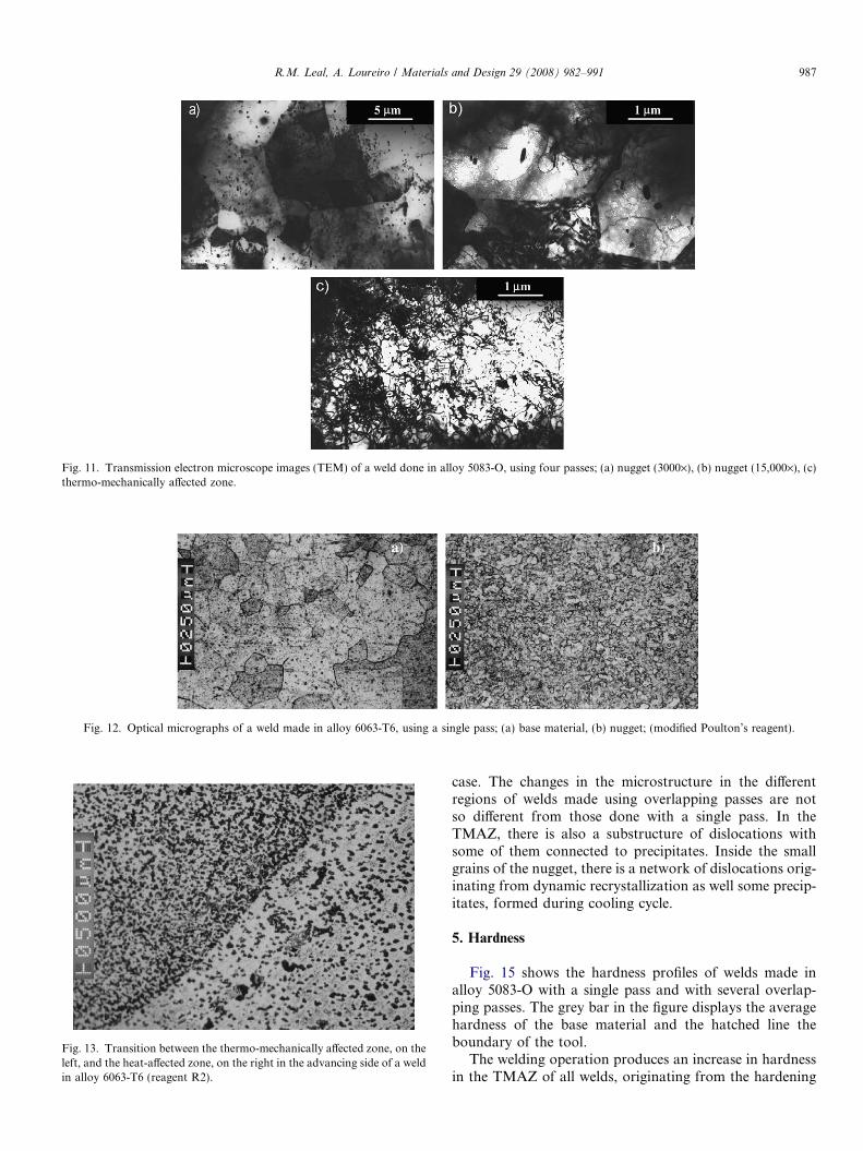
Fig. 11. Transmission electron microscope images (TEM) of a weld done in alloy 5083-O, using four passes; (a) nugget (3000·), (b) nugget (15,000·), (c)thermo-mechanically affected zone.
Fig. 12. Optical micrographs of a weld made in alloy 6063-T6, using a single pass; (a) base material, (b) nugget; (modified Poulton’s reagent).
Fig. 13. Transition between the thermo-mechanically affected zone, on theleft, and the heat-affected zone, on the right in the advancing side of a weldin alloy 6063-T6 (reagent R2).
R.M. Leal, A. Loureiro / Materials and Design 29 (2008) 982–991 987
case. The changes in the microstructure in the differentregions of welds made using overlapping passes are notso different from those done with a single pass. In theTMAZ, there is also a substructure of dislocations withsome of them connected to precipitates. Inside the smallgrains of the nugget, there is a network of dislocations orig-inating from dynamic recrystallization as well some precip-itates, formed during cooling cycle.
5. Hardness
Fig. 15 shows the hardness profiles of welds made inalloy 5083-O with a single pass and with several overlap-ping passes. The grey bar in the figure displays the averagehardness of the base material and the hatched line theboundary of the tool.
The welding operation produces an increase in hardnessin the TMAZ of all welds, originating from the hardening
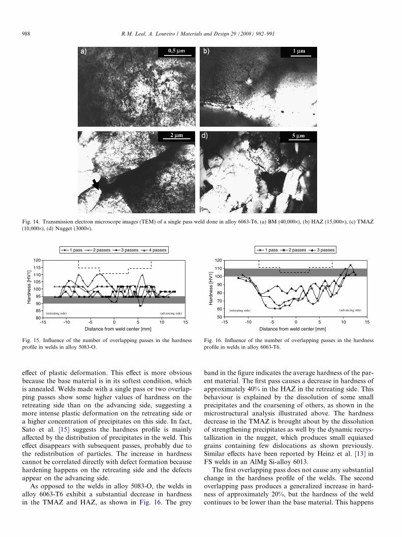
Fig. 14. Transmission electron microscope images (TEM) of a single pass weld done in alloy 6063-T6, (a) BM (40,000·), (b) HAZ (15,000·), (c) TMAZ(10,000·), (d) Nugget (3000·).
80
85
90
95
100
105
110
115
120
-15 -10 -5 0 5 10 15
Distance from weld center [mm]
Har
dnes
s [H
V1]
1 pass 2 passes 3 passes 4 passes
(advancing side) (retreating side)
Fig. 15. Influence of the number of overlapping passes in the hardnessprofile in welds in alloy 5083-O.
50
60
70
80
90
100
110
120
-15 -10 -5 0 5 10 15
Distance from weld center [mm]
Har
dnes
s [H
V1]
1 pass 2 passes 3 passes
(retreating side) (advancing side)
Fig. 16. Influence of the number of overlapping passes in the hardnessprofile in welds in alloy 6063-T6.
988 R.M. Leal, A. Loureiro / Materials and Design 29 (2008) 982–991
effect of plastic deformation. This effect is more obviousbecause the base material is in its softest condition, whichis annealed. Welds made with a single pass or two overlap-ping passes show some higher values of hardness on theretreating side than on the advancing side, suggesting amore intense plastic deformation on the retreating side ora higher concentration of precipitates on this side. In fact,Sato et al. [15] suggests the hardness profile is mainlyaffected by the distribution of precipitates in the weld. Thiseffect disappears with subsequent passes, probably due tothe redistribution of particles. The increase in hardnesscannot be correlated directly with defect formation becausehardening happens on the retreating side and the defectsappear on the advancing side.
As opposed to the welds in alloy 5083-O, the welds inalloy 6063-T6 exhibit a substantial decrease in hardnessin the TMAZ and HAZ, as shown in Fig. 16. The grey
band in the figure indicates the average hardness of the par-ent material. The first pass causes a decrease in hardness ofapproximately 40% in the HAZ in the retreating side. Thisbehaviour is explained by the dissolution of some smallprecipitates and the coarsening of others, as shown in themicrostructural analysis illustrated above. The hardnessdecrease in the TMAZ is brought about by the dissolutionof strengthening precipitates as well by the dynamic recrys-tallization in the nugget, which produces small equiaxedgrains containing few dislocations as shown previously.Similar effects have been reported by Heinz et al. [13] inFS welds in an AlMg Si-alloy 6013.
The first overlapping pass does not cause any substantialchange in the hardness profile of the welds. The secondoverlapping pass produces a generalized increase in hard-ness of approximately 20%, but the hardness of the weldcontinues to be lower than the base material. This happens

Table 2Tensile properties of the base material and welds in alloy 5083-O
Reference ry
(MPa)ru
(MPa)er
(%)g Localization of
fracture
AA 5083-O 99 256 18.8 – BMThree
passesL 101 259 16.3 1 BMS 118 274 21 1.2 TMAZ
Fourpasses
L 107 265 15.3 1.1 BMS 109 268 18 1.1 TMAZ
ry – Yield stress; ru – tensile strength; er – elongation on fracture; g – jointefficiency; L – long specimen (gauge length = 50 mm); S – short specimen(gauge length = 12.5 mm); BM – base material; TMAZ – thermo-mechanically affected zone.
R.M. Leal, A. Loureiro / Materials and Design 29 (2008) 982–991 989
because the first two passes cause the softest condition ofthe material, by dissolution or coarsening of precipitates,and the main mechanism in the third pass is the hardeningeffect by plastic deformation.
6. Tensile properties
The execution of several overlapping passes also affectsthe tensile properties of the welds. Tensile testing was per-formed on specimens removed from welds made usingthree and four overlapping passes in alloy 5083-O. No ten-sile testing was done on welds containing defects such as inthose made using single and two passes.
The tensile specimens fractured within the parent mate-rial, which proves the welding operation leads to an increasein the tensile strength of the weld zone in the welds madewith three or four overlapping passes. These results arecoherent with hardness measurements shown above(Fig. 15). Fig. 17 illustrates the tensile curves of specimensremoved from welds made with three and four overlappingpasses. Curves containing the symbol S correspond to shortspecimens (gauge length = 12.5 mm) removed at rightangles to the welding direction, sampling only the thermo-mechanically affected zone instead of sampling the threezones (TMAZ, HAZ and BM) altogether, as is the case ofthe other long, welded specimens (gauge length = 50 mm).A tensile curve of the base material is also illustrated inthe same diagram. The average tensile properties of the par-ent material and welds are indicated in Table 2.
The efficiency of the welds (proportion of the yield stres-ses of the welded specimen to the base material) is equal to1 and the elongation on fracture of welds made with threeand four overlapping passes is close to the elongation ofthe base material. The curves of short specimens are abovethe curve of the parent material, showing the hardeningeffect of the welding process in this alloy on the annealedcondition. This small increase in strength in the TMAZcomes from the plastic deformation of the material and
0 0.05 0.1 0.15 0.2
e [mm/mm]
0
100
200
300
s [M
Pa]
3 passes
3 passes S
4 passes S
BM
4 passes
Fig. 17. Tensile testing curves of welds performed with three and fouroverlapping passes in alloy 5083-O; S – short specimens; BM – basematerial.
from the grain refinement in the nugget. This change is instrong agreement with the increase in hardness mentionedpreviously.
The tensile specimens removed from the welds in alloy6063-T6 always fractured in the transition between TMAZand HAZ, on the retreating side. This is in agreement withthe results of hardness tests that show the lowest values ofhardness in this zone (see Fig. 16). Fig. 18 illustrates thetensile curves of several types of specimens removed fromwelds in this alloy. Specimens with a gauge length of50 mm were used in testing the base material and the weldsperformed with a single pass and in two and three overlap-ping passes, sampling the three zones of the welds (TMAZ,HAZ and BM). Short specimens, with a gauge length of12.5 mm and referenced by a symbol S, were used to testthe TMAZ of welds done in a single pass and in two andthree overlapping passes. The same figure also shows thetensile curve of a polished specimen (indicated by the sym-bol pol), removed from welds done in a single pass, in orderto show the effect of removing the surface and root weldimperfections on the tensile curve. The average mechanicalproperties of base material and welds are shown in Table 3.
Welds done in a single pass show a significant decreasein yield and tensile strengths, because of the dissolution ofprecipitates and dynamic recrystalization in the nugget, asmentioned above. The realization of subsequent overlap-
0 0.05 0.1 0.15 0.20 0.25 0.3 0.35
e [mm/mm]
0
50
100
150
200
250
s [
MPa
]
2 passes 1 pass 3 passes BM1 pass pol 1 pass S 3 passes S
Fig. 18. Tensile testing curves of welds made using single and severaloverlapping passes in alloy 6063-T6; S – short specimens; BM – basematerial; pol – polished specimen.

Table 3Mechanical properties of the base material and welds in alloy 6063-T6
Reference ry (MPa) ru (MPa) er (%) g Fracture
AA 6063-T6 179 208 9.8 – BMOne pass L 84 137 7.5 0.47 RS
S 112 179 34 0.63 TMAZL pol 111 178 10 0.62 RS
Two passes L 82 130 5.3 0.46 RSS 124 188 35 0.69 TMAZ
Three passes L 93 140 5.2 0.52 RSS 124 189 30 0.69 TMAZ
ry – Yield stress; ru – tensile strength; er – elongation on fracture; g – jointefficiency; L – long specimen (gauge length = 50 mm); S – short specimen(gauge length = 12.5 mm); BM – base material; TMAZ – thermo-mechanically affected zone; RS – heat-affected zone, retreating side; pol –polished.
990 R.M. Leal, A. Loureiro / Materials and Design 29 (2008) 982–991
ping passes produces a marginal increase in the tensilestrength of the welds. The efficiency of welds made inone, two or three passes is respectively 0.47, 0.46 and0.52.
The polishing operation increased the yield and tensilestrengths of the welded specimens. In fact the efficiency isan average of 0.47 for non-polished welds and 0.62 for pol-ished welds done in a single pass. There is some industrialpredisposition to leave welds in the as-welded condition,however, these results show weld polishing improves theperformance of the welded joints.
The TMAZ of the welds has a tensile strength above thetensile strength of the HAZ as shown by the tensile curvesof the short specimens. Consequently the HAZ is the weak-est zone of the weld, as suggested by the hardness tests(Fig. 16). As mentioned previously, specimens fracturedin the transition between the TMAZ and the HAZ, onthe retreating side. Moreover, the TMAZ has better plas-ticity than the parent material (approximately 30% com-pared to 10% of the parent material), as shown inFig. 18. This feature explains why these undermatchedwelds do not induce a significant reduction in the elonga-tion of tensile specimens. In fact, undermatched welds tendto concentrate plastic deformation in the weakest zone ofthe weld leading to premature fracture of the specimens.A supplementary factor that contributes to the strong plas-tic performance of the welds is the large widths of the softzone around (20 mm) (see Fig. 16). The plastic deformationof this zone compensates for the small deformation of theparent material because of the undermatched conditionof the welds.
7. Conclusions
This study showed that the effect of the friction stirwelding process on the quality and strength of welds isnot just a function of the main welding parameters but alsoof the material and its condition of treatment. The samecan be said with regard to the application of overlapping
passes. Because of this the conclusions of this work are pre-sented in two separate items, respectively for alloys AA5083-O and AA 6063-T6.
AA 5083-O� The accomplishment of a single pass or two overlapping
passes in this alloy, using the process parameters speci-fied, produces superficial or sub-superficial voids alongthe entire length of the welds.
� The completion of three or four overlapping passesusing the same process parameters allows the defectsto be eliminated, suggesting that the execution of over-lapping passes can be a good technique for repairingdefective welds.
� This technique does not change the microstructure ofthe welds substantially, and produces a modest increasein hardness.
� The welds in three and four overlapping passes have effi-ciency of 1.0.
Alloy 6063-T6� Friction stir welding in this material leads to a substan-
tial decrease in hardness and in tensile strength in thethermo-mechanically affected zone and heat-affectedzone of the welds due to the dissolution and coarseningof strengthening precipitates.
� The completion of several overlapping passes produces amarginal increase in the hardness and tensile strength ofthe welds.
� Polishing operations on the face and root sides canimprove the mechanical efficiency of the welds up to15%.
Acknowledgements
The European Community and the PortugueseGovernment financially supported this work throughFundacao para a Ciencia e Tecnologia. The companyESAB collaborated in the accomplishment of the welds.Professor V. Fernandes supported the TEM work. Theauthors acknowledge all the support.
References
[1] Huang C, Kou S. Partially melted zone in aluminium welds –liquation mechanisms and directional solidification. Weld J2000;79(5):113s–20s.
[2] Zhao H, White DR, DebRoy T. Current issues and problems in laserwelding of automotive aluminium alloys. Int Mater Rev 1999;44(6):238–66.
[3] Chao YJ, Qi X, Tang W. Heat transfer in friction stir welding –experimental and numerical studies. Trans ASME 2003(125):138–45.
[4] Thomas WM, Nicholas ED, Needham JC, Murch MG, TemplesmithP, Dawes CJ. GB Patent Application No. 9125978.8 Dec. 1991, USPatent No 5460317, Oct 1995.
[5] Cao G, Kou S. Friction stir welding of 2219 aluminum: behaviour ofh(Al2Cu) particles. Weld J 2005;84(1):1s–8s.

R.M. Leal, A. Loureiro / Materials and Design 29 (2008) 982–991 991
[6] Won-Bae Lee, Yun-Mo Yeon, Seung-Boo Jung. The jointproperties of dissimilar formed Al alloys by friction stir weldingaccording to the fixed location of materials, Scripta Materi 2003;49:423–8.
[7] Kimapong K, Watanabe T. Friction stir welding of aluminium alloyto steel. Weld J 2004;83(10):277s–82s.
[8] Sutton MA, Reynolds AP, Wang DQ, Hubbard CR. A study ofresidual stresses and microstructure in 2024-T3 aluminium frictionstir butt welds. J Eng Mater Tech 2002;124:215–21. Transactions ofthe ASME.
[9] Leal R, Loureiro A. Defects formation in friction stir welding ofaluminium alloys. Mater Sci Forum 2004;455–6:299–302.
[10] Peel M, Steuwer A, Preuss M, Withers PJ. Microstructure, mechan-ical properties and residual stresses as a function of welding speed inaluminium AA5083 friction stir welds, Acta Mater 2003;51:4791–801.
[11] Leal RM, Loureiro A. Microstructure and mechanical properties offriction stir welds in aluminium alloys 2024-T3, 5083-O and 6063-T6.Mater Sci Forum 2006;514–6:697–701.
[12] Kwon YJ, Saito N, Shigematsu I. Friction stir process as a newmanufacturing technique of ultrafine grained aluminum alloy. JMater Sci Lett 2002;21:1473–6.
[13] Heinz B, Skrotzki B, Eggeler G. Microstructural and mechanicalcharacterization of a friction stir welded Al alloy. Mater Sci Forum2000;331–7:1757–62.
[14] Sato YS, Kokawa H, Enomoto M, Jogan S. Microstructuralevolution of 6063 aluminum during friction-stir welding. MetallMater Trans A 1999;30A(September):2429–37.
[15] Sato YS, Hwan S, Park C, Kokawa H. Microstructural factorsgoverning hardness in friction-stir welds of solid-solution-hardenedAl alloys. Metall Mater Trans A 2001;32A(December):3033–41.


![Non-destructive Evaluation of Friction Stir Welded Joints ... · strength of the FSW joint for AC4C Al alloy and Steel dissimilar friction stir lap joints [7]. Aluminum alloy welds](https://img.pdfslide.net/doc/110x75/5e5c511832f9297d8a597cf4/non-destructive-evaluation-of-friction-stir-welded-joints-strength-of-the-fsw.jpg)