Embed Size (px)
Citation preview
polymers
Article
Effect of Polyaniline on Sulfur/Sepiolite CompositeCathode for Lithium-Sulfur Batteries
Kalaiselvi Chelladurai 1, Priyanka Venkatachalam 1, Subadevi Rengapillai 1,*, Wei-Ren Liu 2,Chia-Hung Huang 3 and Sivakumar Marimuthu 1,*
1 #120, Energy Materials Lab, Department of Physics, Science Block, Alagappa University, Karaikudi 630 003,Tamil Nadu, India; [email protected] (K.C.); [email protected] (P.V.)
2 Department of Chemical Engineering, R&D Center for Membrane Technology, Research Center for CircularEconomy, Chung-Yuan Christian University, Chung-Li 32023, Taiwan; [email protected]
3 Metal Industries Research and Development Centre, Kaohsiung 81160, Taiwan; [email protected]* Correspondence: [email protected] (S.R.); [email protected] (S.M.)
Received: 22 February 2020; Accepted: 25 March 2020; Published: 31 March 2020�����������������
Abstract: Composite materials with a stable network structure consisting of natural sepiolite(Sp) powders (both sieved sepiolite and post-treated sepiolite), sulfur(S), and conductive polymerPolyaniline (PAni) have been successfully synthesized using a simple heat treatment. The morphologyof composites illustrates that the sepiolite is composed of many needle-like fibrous clusters. The initialdischarge capacity of the post-treated sepiolite/sulfur/PAni composite is about 1230 mA h g−1 at 0.1 C,and it remains at 826 mA h g−1 even after 40 cycles with the corresponding coulombic efficiencyabove 97%. Such performance is attributed to the specific porous structure, outstanding adsorptioncharacteristics, and excellent ion exchange capability of sepiolite, as well as the excellent conductivityof PAni. In addition, the PAni coating has a pinning effect on sulfur, which influences the consumptionof the active mass and enhances the cycling constancy and the coulombic efficiency of the compositematerial at elevated current rates.
Keywords: sepiolite; polyaniline; XRD; SEM; electrochemical studies
1. Introduction
Rechargeable Lithium-ion batteries (LIBs) are one of the remarkable power sources for electricvehicles and portable electronic devices. The increasing demands of advanced electronic devices andelectric vehicles, the development of high energy density, low cost, and long cycling performancebatteries are of great importance. Among the rechargeable lithium battery family, the Lithium-sulfur(Li–S) battery offers a high theoretical specific capacity of 1675 mA h g−1 and energy density of2600 Wh kg−1 [1–4]. Besides the high theoretical capacity, sulfur has the advantages of abundance,non-toxicity, environmental friendliness, cost worthiness, and wide operating temperature rangewhen used as the positive electrode [5,6]. However, there are several serious of problems in realizingthe practical applications of the Li–S battery. First, the poor conductivity of sulfur and its dischargeproducts leads to low utilization of the active material. Second, the huge volume expansion activematerial during lithiation/delithiation, which causes the structure of cathode; Third, the shuttle effectpolysulfides, resulting in a rapid capacity fading and low columbic efficiency [7–10].
To confront the fact that sulfur containing organic compounds are highly electrically and ionicallyinsulating and to enable a reversible electrochemical reaction at high current rates, carbon materialshave been implemented [11]. The use of structured carbons with designed porosity and a high surfacearea for sulfur storage aids the sulfur in maintaining intimate contact with an electrically conductiveadditive [12]. They allow to encapsulate the sulfur particles within the cathode and to mitigate the
Polymers 2020, 12, 755; doi:10.3390/polym12040755 www.mdpi.com/journal/polymers
Polymers 2020, 12, 755 2 of 13
lithium polysulfide (LiPS) dissolution as well as buffer the huge volume change of the active materialduring lithiation and delithiation process [13].
Sepiolite is a hydrated magnesium silicate clay mineral with layered chain structure and it portraysfibrous morphology. It could be an excellent matrix and absorbing material for Li–S batteries due to itslarge pore volume and ion transmission channel. Also, it enables good conversion efficiency of activematerial due to the strong adsorption of sepiolite and polysulfides. However, the sepiolite has poorelectrical conductivity and its impurity leads to low coulombic efficiency [14–16].
On the other hand, in order to surmount the chronic technical issues impeding the Li–S technologyfrom practical applications, the sulfur-conductive polymer composites started with the applicationof PAN. Since then, as an alternative to carbon coating, sulfur has also been embedded with variousconductive polymers during the past decade [17–20]. The properties of conducting polymers dependstrongly on the doping level, protonation level, ion size of dopant, and water content [21]. Zhou et al.explained S-PAni core–shell composites using chemical oxidative polymerisation method on thesurface of sulfur nanospheres [22]. PAni enhances the conductivity while alleviating the diffusionof LiPSs [23,24]. A more efficient consumption of PAni as conductive medium to obstruct the LiPSsuspension was initiated by Xiao et al. Moreover, PAni has a massive electrical conductivity, elevatedchemical stability and simply synthesis that it can be able to manage oxidation state and degree ofprotonation [25]. The strong chemical binding nature of PAni is a key factor for to immobilize thepolysulfide and easily transport the electron for enhancing the electrochemical performance [26].
In this work, S/PTSp/PAni composite material was prepared via simple heat treatment. The polymermolecular scaffold provides strong physical and chemical internment to the elemental sulfur and theresident polysulfide. In addition, the polymer matrix, clay mineral sepiolite, and nano structured sulfurallows for the reversible deposition of transitional polysulfide species during discharge, and theirensuing conversion during recharge within the polymer matrix, as well as an investigation of itsphysical and electrochemical properties as a cathode for lithium rechargeable batteries.
2. Experimental
2.1. Sepiolite Acid Treatment
Sieved 200-mesh sepiolite powder, Hydrochloric acid (HCl), de-ionized water and Polyanilinepolymer was purchased from Sigma Aldrich (St. Louis, MI, USA). Acid treatment was passed out using8 mole ratio of Hydrochloric acid was added with deionized water in a beaker without disconcertingat surrounding temperature for 24 h. The clay minerals were filtered and washed with de-ionizedwater for frequent times, and then desiccated at 40 ◦C in a vacuum oven at 10−3 Torr for 12 h.
2.2. Thermal Activation Method
The post-treated sieved sepiolite powders were composed according to the above treatment.In this process, 8 mole ratios of post-treated sepiolite, sublimed sulfur, and PAni (7:2:1) were passedthrough fine grinding for 1 h and then heated at 155 ◦C for 20 h in a muffle furnace. The collectedsample was milled and dried to the get final product.
2.3. Characterization
The X-ray diffraction patterns and functional groups of calcined powder samples were examinedby using X-ray diffraction (PAN alytical XPERT-PRO with Cu-Kα radiation, Malvem panalytical,Leyweg, EA Almelo, The Netherlands) and FTIR spectrometer recording IR spectra in the range of4000–500 cm−1 using (Thermo Nicolet 380 Instrument Cooperation and KBr pellets, Woodland, CA,USA). The morphology of the powders was inspected by scanning electron microscope (EV018 (CARLZEISS) Jena, Germany) and transmission electron microscope (TEM, JEOL, Musashino, Akishima-Shi,Tokyo, Japan) with energy dispersive X-ray spectroscopy (EDS). Raman spectroscopy (Renishaw inVia,excited by a 514 nm Ar-ion laser with a laser spot size of ~1 µm2, Japan) was used to characterize the
Polymers 2020, 12, 755 3 of 13
electron shift. X-ray photoelectron spectroscopy (XPS) data were obtained employing a Phi 5300 X-rayPhotoelectron Spectrometer (THERMO SCIENTIFIC, Waltham, MA, USA) with Mg K-alpha X-rays atan accelerating voltage of 15.0 kV (hν = 1253.6 eV) in a chamber maintained at 10−9 Torr.
2.4. Electrochemical Performance
Positive electrodes comprised of 70 wt % S/PTSp/PAni composite, 20 wt % acetylene black and10 wt % polyvinylidene fluoride binders were evenly mixed in an N-methyl-2-pyrrolidone (NMP)solvent under incessant magnetic stirring for 3 h, and then the slurry was homogeneously coatedon an aluminum foil. The electrodes were dried under vacuum at 60 ◦C for 12 h. CR2032 typecoin cells were assembled in an argon-filled glove box, where lithium metal was used as a counterelectrode and polypropylene membrane was used as the separator. The electrolyte was 1 M lithium bis(tri-fluoro methane sulfonyl) imide (LiTFSI) dissolved in a 1:1 volume ratio mixture of 1, 3-dioxolaneand dimethoxy ethane. Electrochemical charge–discharge and cyclic performances were calculated atroom temperature using a BTS-5V3A battery test system (Neware, Shenzhen, China), with the potentialrange from 3.0 to 1.5 V (vs. Li/Li+).
3. Results and Discussion
3.1. XRD Analysis
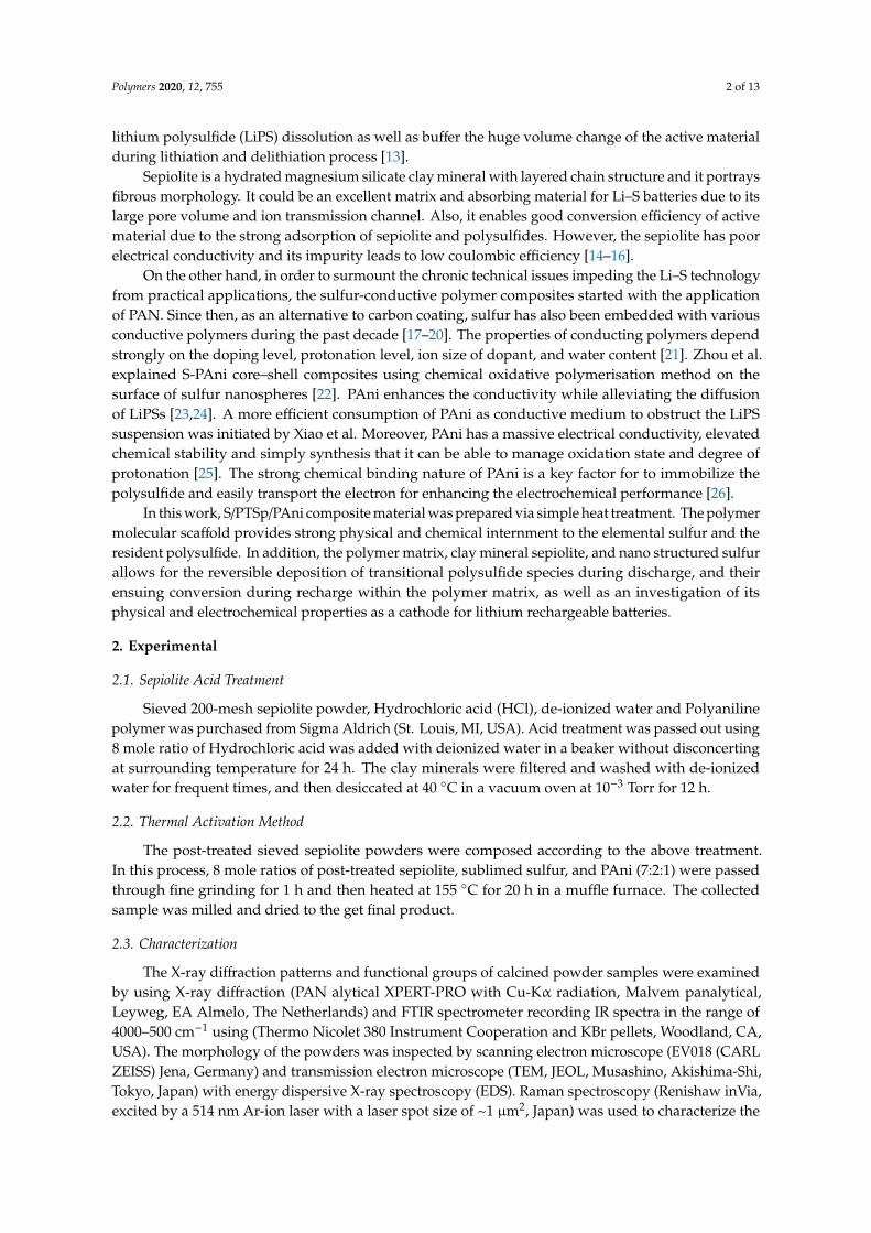
The XRD patterns of SvSp, pure sulfur, PAni and composite materials such as S/PTSp/PAni andS/SvSp/PAni are shown in Figure 1. From Figure 1a it was observed that sample exhibits a strongdiffraction peaks appeared at 2θ = 7.45◦ which corresponds to the (110) crystal planes of sieved sepiolite.The orthorhombic structure of sublimed sulfur was confirmed by reference pattern (JCPDS No. 08-0247).On the other hand, the PAni sample possessed an amorphous nature without sharp crystalline peaks.After the impregnation of sulfur, the diffraction peaks of S/SvSp/PAni and S/PTSp/PAni are well matchedwith bare sublimed sulfur, which indicates the homogeneous distribution of the active material.
Polymers 2019, 11, x FOR PEER REVIEW 3 of 14
(Renishaw inVia, excited by a 514 nm Ar‐ion laser with a laser spot size of ~1 μm2, Japan) was used
to characterize the electron shift. X‐ray photoelectron spectroscopy (XPS) data were obtained
employing a Phi 5300 X‐ray Photoelectron Spectrometer (THERMO SCIENTIFIC, Waltham, MA,
USA) with Mg K‐alpha X‐rays at an accelerating voltage of 15.0 kV (hν = 1253.6 eV) in a chamber
maintained at 10−9 Torr.
2.4. Electrochemical Performance
Positive electrodes comprised of 70 wt % S/PTSp/PAni composite, 20 wt % acetylene black and
10 wt %polyvinylidene fluoride binders were evenly mixed in an N‐methyl‐2‐pyrrolidone (NMP)
solvent under incessant magnetic stirring for 3 h, and then the slurry was homogeneously coated on
an aluminum foil. The electrodes were dried under vacuum at 60 °C for 12 h. CR2032 type coin cells
were assembled in an argon‐filled glove box, where lithium metal was used as a counter electrode
and polypropylene membrane was used as the separator. The electrolyte was 1 M lithium bis (tri‐
fluoro methane sulfonyl) imide (LiTFSI) dissolved in a 1:1 volume ratio mixture of 1, 3‐dioxolane and
dimethoxy ethane. Electrochemical charge–discharge and cyclic performances were calculated at
room temperature using a BTS‐5V3A battery test system (Neware, Shenzhen, China), with the
potential range from 3.0 to 1.5 V (vs. Li/Li+).
3. Results and Discussion
3.1. XRD Analysis
Figure 1. Patterns of (a) sieved sepiolite (SvSp), (b) pure sulfur (PS), (c) Polyaniline (PAni), (d)
sulfur/sieved sepiolite/PAni (S/SvSp/PAni), (e) sulfur/post‐treated sepiolite/PAni(S/PTSp/PAni).
The XRD patterns of SvSp, pure sulfur, PAni and composite materials such as S/PTSp/PAni and
S/SvSp/PAni are shown in Figure 1. From Figure 1(a) it was observed that sample exhibits a strong
diffraction peaks appeared at 2θ = 7.45° which corresponds to the (110) crystal planes of sieved
sepiolite. The orthorhombic structure of sublimed sulfur was confirmed by reference pattern (JCPDS
No. 08‐0247). On the other hand, the PAni sample possessed an amorphous nature without sharp
Figure 1. Patterns of (a) sieved sepiolite (SvSp), (b) pure sulfur (PS), (c) Polyaniline (PAni),(d) sulfur/sieved sepiolite/PAni (S/SvSp/PAni), (e) sulfur/post-treated sepiolite/PAni(S/PTSp/PAni).
Polymers 2020, 12, 755 4 of 13
3.2. FTIR Analysis
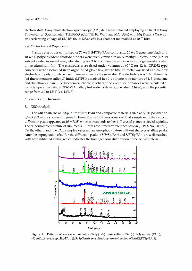
The FTIR spectra of S/PTSp/PAni composite materials are as shown in Figure 2, which exemplifiedthe occurrence of chemical bonds and functional groups of the composite material in the range of4000 to 400 cm−1. The elemental sulfur was confirmed by the C–S stretching vibration band appearedaround 500 cm−1. The vibrational peaks appeared in the range 1200–400 cm−1 is consigned to thecharacteristic peak of silicate. The characteristic absorption peak at 1030 cm−1 is assigned to Si-Ostretching and bending of sepiolite clay mineral [27]. The two peaks arising at 1475 and 1557 cm−1 aredue to the benzenoid and quinoid-ring vibration of PAni, which are clearly indicating the oxidationstate of emeraldine base polyaniline [28]. The infrared peak at 1131 cm−1 is a vibrational mode of–N=quinoid=N– stretching and it confirmed the conducting state of polyaniline deposited on thesurface of S/PTSp composite [29]. The vibrational peak at 2904 cm−1 is attributed to the N–H stretchingmode of PAni. Therefore, the FTIR analysis reveals that PAni acts as an excellent connector betweenactive material and porous nature of sepiolite.
Polymers 2019, 11, x FOR PEER REVIEW 4 of 14
crystalline peaks. After the impregnation of sulfur, the diffraction peaks of S/SvSp/PAni and
S/PTSp/PAni are well matched with bare sublimed sulfur, which indicates the homogeneous
distribution of the active material.
3.2. FTIR Analysis
The FTIR spectra of S/PTSp/PAni composite materials are as shown in Figure2, which
exemplified the occurrence of chemical bonds and functional groups of the composite material in the
range of 4000 to 400 cm−1. The elemental sulfur was confirmed by the C–S stretching vibration band
appeared around 500 cm−1. The vibrational peaks appeared in the range 1200–400 cm−1 is consigned
to the characteristic peak of silicate. The characteristic absorption peak at 1030 cm−1 is assigned to Si‐
O stretching and bending of sepiolite clay mineral [27]. The two peaks arising at 1475 and 1557 cm−1
are due to the benzenoid and quinoid‐ring vibration of PAni, which are clearly indicating the
oxidation state of emeraldine base polyaniline [28]. The infrared peak at 1131 cm−1 is a vibrational
mode of –N=quinoid=N– stretching and it confirmed the conducting state of polyaniline deposited
on the surface of S/PTSp composite [29]. The vibrational peak at 2904 cm−1 is attributed to the N–H
stretching mode of PAni. Therefore, the FTIR analysis reveals that PAni acts as an excellent
connector between active
Figure 2. Spectrum of (a) PAni(b) sulfur/sieved sepiolite/PAni (S/SvSp/PAni) and (c) sulfur/post‐
treated sepiolite/PAni (S/PTSp/PAni).
3.3. Raman Spectroscopy
Raman spectra of pure sulfur, PAni, PS/PAni and composite are presented in Figure 3. The pure
sulfur displays a characteristic peak below 500 cm−1 corresponding to A1 symmetry mode of S–S
bond. From Figure 3(b) the quinoid and benzenoid rings are confirmed to the pattern of emeraldine
structure of PAni [30]. In Figure 3c, even after the infusion of sulfur into the PAni, the peaks of sulfur
are still not visible as it is thoroughly wrapped by PAni. In the S/PTSp/PAni composite, the intensity
of the sulfur peaks are very low, signifying the good dispersion of sulfur within the polymer matrix.
Figure 2. Spectrum of (a) PAni (b) sulfur/sieved sepiolite/PAni (S/SvSp/PAni) and (c) sulfur/post-treatedsepiolite/PAni (S/PTSp/PAni).
3.3. Raman Spectroscopy
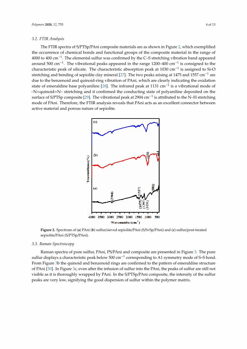
Raman spectra of pure sulfur, PAni, PS/PAni and composite are presented in Figure 3. The puresulfur displays a characteristic peak below 500 cm−1 corresponding to A1 symmetry mode of S–S bond.From Figure 3b the quinoid and benzenoid rings are confirmed to the pattern of emeraldine structureof PAni [30]. In Figure 3c, even after the infusion of sulfur into the PAni, the peaks of sulfur are still notvisible as it is thoroughly wrapped by PAni. In the S/PTSp/PAni composite, the intensity of the sulfurpeaks are very low, signifying the good dispersion of sulfur within the polymer matrix.
Polymers 2020, 12, 755 5 of 13Polymers 2019, 11, x FOR PEER REVIEW 5 of 14
Figure 3. Spectra of (a) PS,(b) PAni(c) PS/PAni,(d) Sulfur/post‐treated sepiolite/PAni (S/PTSp/PAni).
3.4. Morphological Analysis
3.4.1. SEM Analysis
Figure 3. Spectra of (a) PS, (b) PAni, (c) PS/PAni, (d) Sulfur/post-treated sepiolite/PAni (S/PTSp/PAni).
3.4. Morphological Analysis
3.4.1. SEM Analysis
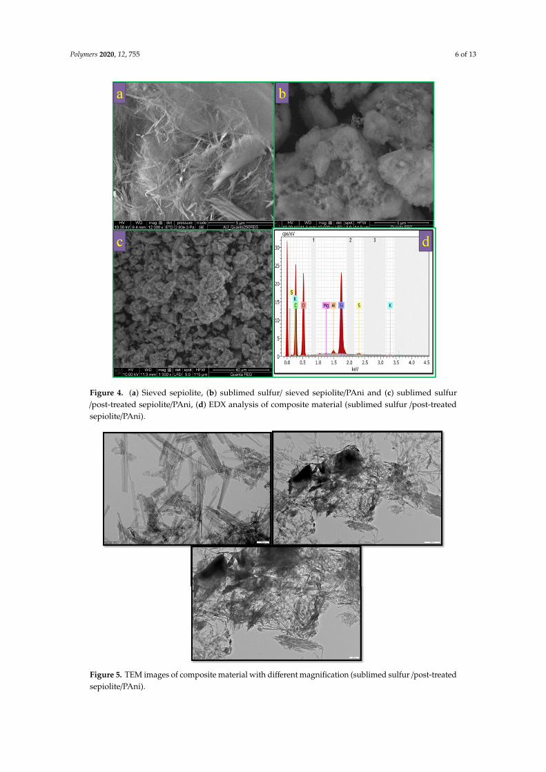
The morphology of sepiolite was further examined by SEM and TEM analyses. From Figure 4a,it is observed that the sepiolite powder consists of short micro-fibrous bundles. Figure 4b,c showsthe morphology after sulfur and PAni inserting in sieved and post-treated sepiolite. After sulfurinoculation with closed integration of sulfur and sepiolite was appeared which increases the averagediameter of the fibers and also is consistent with the XRD result suggests no structure change in thecomposite. The presence of sulfur was analyzed by the EDX shown in Figure 4d. Moreover, the elementdistributions of Si, O, C, and S are in the composite elucidated. The Si element is ascribed to sepiolite,while the element O and C due to polyaniline (PAni).
3.4.2. TEM Analysis
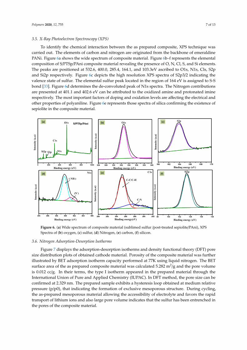
The microstructure of the composite cathode found that the sepiolite exhibited needle-like fibrousclusters (Figure 5). After the sulfur interjects, perceptible aggregation appears owing to thermaltreatment. The results demonstrate that PAni has been successfully deposited on the compositematerial. Since the oxidation reactions can only occur at the S/SvSp/PAni and S/PTSep/PAni samplesinterface during charging/discharging process, the highly uniform distribution of PAni coating canincrease the contact area between PAni and the electrolyte, and hence increase the number of activesites for electrochemical reaction in Li–S batteries [31,32].
Polymers 2020, 12, 755 6 of 13Polymers 2019, 11, x FOR PEER REVIEW 6 of 14
Figure 4. (a) sieved sepiolite,(b) sublimed sulfur/ sieved sepiolite/PAni and (c,d) sublimed sulfur
/post‐treated sepiolite/PAni,(e) EDX analysis of composite material (sublimed sulfur /post‐treated
sepiolite/PAni).
The morphology of sepiolite was further examined by SEM and TEM analyses. From Figure 4(a),
it is observed that the sepiolite powder consists of short micro‐fibrous bundles. Figure 4(b) and (c)
shows the morphology after sulfur and PAni inserting in sieved and post‐treated sepiolite. After
sulfur inoculation with closed integration of sulfur and sepiolite was appeared which increases the
average diameter of the fibers and also is consistent with the XRD result suggests no structure change
in the composite. The presence of sulfur was analyzed by the EDX shown in Figure 4d. Moreover, the
element distributions of Si, O, C, and S are in the composite elucidated. The Si element is ascribed to
sepiolite, while the element O and C due to polyaniline (PAni).
3.4.2. TEM Analysis
The microstructure of the composite cathode found that the sepiolite exhibited needle‐like
fibrous clusters (Figure 5). After the sulfur interjects, perceptible aggregation appears owing to
thermal treatment. The results demonstrate that PAni has been successfully deposited on the
composite material. Since the oxidation reactions can only occur at the S/SvSp/PAni and
S/PTSep/PAni samples interface during charging/discharging process, the highly uniform
distribution of PAni coating can increase the contact area between PAni and the electrolyte, and hence
increase the number of active sites for electrochemical reaction in Li–S batteries [31,32].
Figure 4. (a) Sieved sepiolite, (b) sublimed sulfur/ sieved sepiolite/PAni and (c) sublimed sulfur/post-treated sepiolite/PAni, (d) EDX analysis of composite material (sublimed sulfur /post-treatedsepiolite/PAni).Polymers 2019, 11, x FOR PEER REVIEW 7 of 14
Figure 5.TEM images of composite material with different magnification (sublimed sulfur /post‐
treated sepiolite/PAni).
3.5. X‐ray Photoelectron Spectroscopy (XPS)
To identify the chemical interaction between the as prepared composite, XPS technique was
carried out. The elements of carbon and nitrogen are originated from the backbone of emeraldine
PANi. Figure 6a shows the wide spectrum of composite material. Figure 6b–f represents the elemental
composition of S/PTSp/PAni composite material revealing the presence of O, N, Cl, S, and Si
elements. The peaks are positioned at 532.6, 400.0, 285.4, 164.1, and 103.3eV ascribed to O1s, N1s, Cls,
S2p and Si2p respectively. Figure 6c depicts the high resolution XPS spectra of S2p3/2 indicating the
valence state of sulfur. The elemental sulfur peak located in the region of 164 eV is assigned to S‐S
bond [33].Figure 6d determines the de‐convoluted peak of N1s spectra. The Nitrogen contributions
are presented at 401.1 and 402.6 eV can be attributed to the oxidized amine and protonated imine
respectively. The most important factors of doping and oxidation levels are affecting the electrical
and other properties of polyaniline. Figure 6e represents those spectra of silica confirming the
existence of sepiolite in the composite material.
Figure 5. TEM images of composite material with different magnification (sublimed sulfur /post-treatedsepiolite/PAni).
Polymers 2020, 12, 755 7 of 13
3.5. X-Ray Photoelectron Spectroscopy (XPS)
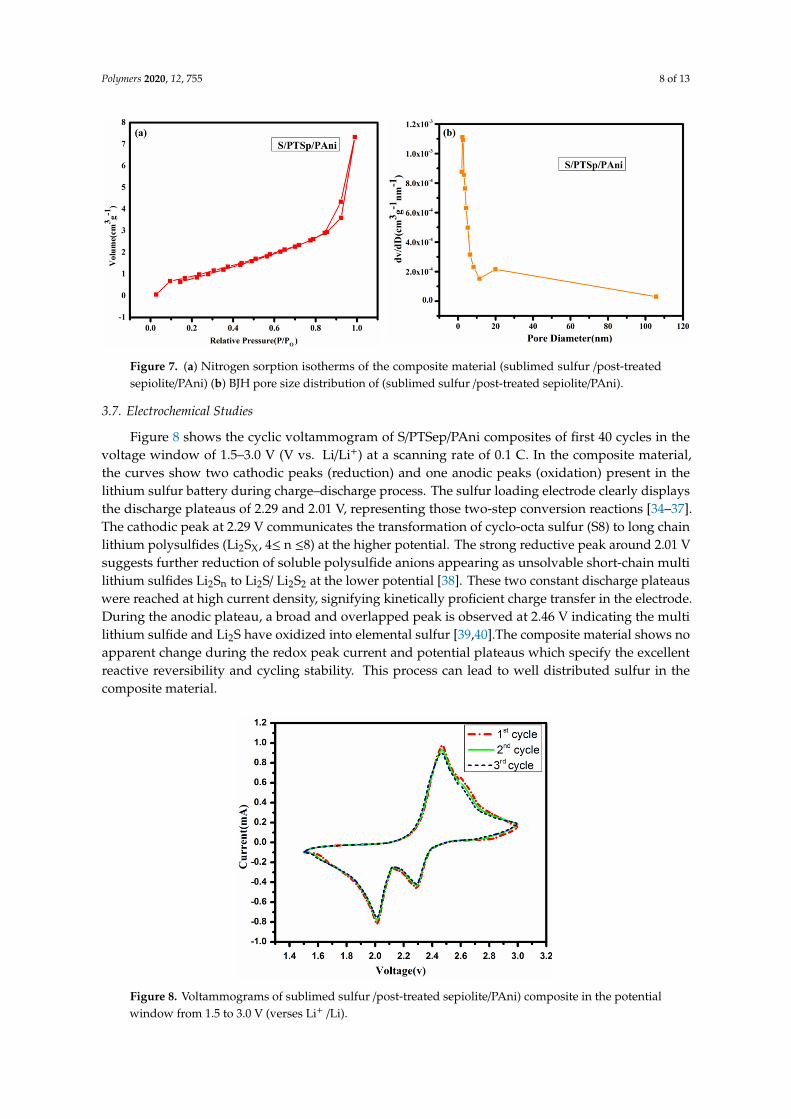
To identify the chemical interaction between the as prepared composite, XPS technique wascarried out. The elements of carbon and nitrogen are originated from the backbone of emeraldinePANi. Figure 6a shows the wide spectrum of composite material. Figure 6b–f represents the elementalcomposition of S/PTSp/PAni composite material revealing the presence of O, N, Cl, S, and Si elements.The peaks are positioned at 532.6, 400.0, 285.4, 164.1, and 103.3eV ascribed to O1s, N1s, Cls, S2pand Si2p respectively. Figure 6c depicts the high resolution XPS spectra of S2p3/2 indicating thevalence state of sulfur. The elemental sulfur peak located in the region of 164 eV is assigned to S-Sbond [33]. Figure 6d determines the de-convoluted peak of N1s spectra. The Nitrogen contributionsare presented at 401.1 and 402.6 eV can be attributed to the oxidized amine and protonated iminerespectively. The most important factors of doping and oxidation levels are affecting the electrical andother properties of polyaniline. Figure 6e represents those spectra of silica confirming the existence ofsepiolite in the composite material.Polymers 2019, 11, x FOR PEER REVIEW 8 of 14
Figure 6. (a) Wide spectrum of composite material (sublimed sulfur /post‐treated sepiolite/PAni), XPS
Spectra of (b) oxygen, (c) sulfur, (d) Nitrogen, (e) carbon, (f) silicon.
3.6. Nitrogen Adsorption‐Desorption Isotherms
Figure 7 displays the adsorption‐desorption isotherms and density functional theory (DFT) pore
size distribution plots of obtained cathode material. Porosity of the composite material was further
illustrated by BET adsorption isotherm capacity performed at 77K using liquid nitrogen. The BET
surface area of the as prepared composite material was calculated 5.282 m2/g and the pore volume is
0.012 cc/g. In their terms, the type I isotherm appeared in the prepared material through the
International Union of Pure and Applied Chemistry (IUPAC). In DFT method, the pore size can be
confirmed at 2.329 nm. The prepared sample exhibits a hysteresis loop obtained at medium relative
pressure (p/p0), that indicating the formation of exclusive mesoporous structure. During cycling, the
as‐prepared mesoporous material allowing the accessibility of electrolyte and favors the rapid
transport of lithium ions and also large pore volume indicates that the sulfur has been entrenched in
the pores of the composite material.
Figure 7. (a) Nitrogen sorption isotherms of the composite material (sublimed sulfur /post‐treated
sepiolite/PAni) (b) BJH pore size distribution of (sublimed sulfur /post‐treated sepiolite/PAni).
Figure 6. (a) Wide spectrum of composite material (sublimed sulfur /post-treated sepiolite/PAni), XPSSpectra of (b) oxygen, (c) sulfur, (d) Nitrogen, (e) carbon, (f) silicon.
3.6. Nitrogen Adsorption-Desorption Isotherms
Figure 7 displays the adsorption-desorption isotherms and density functional theory (DFT) poresize distribution plots of obtained cathode material. Porosity of the composite material was furtherillustrated by BET adsorption isotherm capacity performed at 77K using liquid nitrogen. The BETsurface area of the as prepared composite material was calculated 5.282 m2/g and the pore volumeis 0.012 cc/g. In their terms, the type I isotherm appeared in the prepared material through theInternational Union of Pure and Applied Chemistry (IUPAC). In DFT method, the pore size can beconfirmed at 2.329 nm. The prepared sample exhibits a hysteresis loop obtained at medium relativepressure (p/p0), that indicating the formation of exclusive mesoporous structure. During cycling,the as-prepared mesoporous material allowing the accessibility of electrolyte and favors the rapidtransport of lithium ions and also large pore volume indicates that the sulfur has been entrenched inthe pores of the composite material.
Polymers 2020, 12, 755 8 of 13
Polymers 2019, 11, x FOR PEER REVIEW 8 of 14
Figure 6. (a) Wide spectrum of composite material (sublimed sulfur /post‐treated sepiolite/PAni), XPS
Spectra of (b) oxygen, (c) sulfur, (d) Nitrogen, (e) carbon, (f) silicon.
3.6. Nitrogen Adsorption‐Desorption Isotherms
Figure 7 displays the adsorption‐desorption isotherms and density functional theory (DFT) pore
size distribution plots of obtained cathode material. Porosity of the composite material was further
illustrated by BET adsorption isotherm capacity performed at 77K using liquid nitrogen. The BET
surface area of the as prepared composite material was calculated 5.282 m2/g and the pore volume is
0.012 cc/g. In their terms, the type I isotherm appeared in the prepared material through the
International Union of Pure and Applied Chemistry (IUPAC). In DFT method, the pore size can be
confirmed at 2.329 nm. The prepared sample exhibits a hysteresis loop obtained at medium relative
pressure (p/p0), that indicating the formation of exclusive mesoporous structure. During cycling, the
as‐prepared mesoporous material allowing the accessibility of electrolyte and favors the rapid
transport of lithium ions and also large pore volume indicates that the sulfur has been entrenched in
Figure 7. (a) Nitrogen sorption isotherms of the composite material (sublimed sulfur /post‐treated
sepiolite/PAni) (b) BJH pore size distribution of (sublimed sulfur /post‐treated sepiolite/PAni).
Figure 7. (a) Nitrogen sorption isotherms of the composite material (sublimed sulfur /post-treatedsepiolite/PAni) (b) BJH pore size distribution of (sublimed sulfur /post-treated sepiolite/PAni).
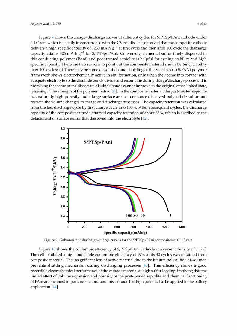
3.7. Electrochemical Studies
Figure 8 shows the cyclic voltammogram of S/PTSep/PAni composites of first 40 cycles in thevoltage window of 1.5–3.0 V (V vs. Li/Li+) at a scanning rate of 0.1 C. In the composite material,the curves show two cathodic peaks (reduction) and one anodic peaks (oxidation) present in thelithium sulfur battery during charge–discharge process. The sulfur loading electrode clearly displaysthe discharge plateaus of 2.29 and 2.01 V, representing those two-step conversion reactions [34–37].The cathodic peak at 2.29 V communicates the transformation of cyclo-octa sulfur (S8) to long chainlithium polysulfides (Li2SX, 4≤ n ≤8) at the higher potential. The strong reductive peak around 2.01 Vsuggests further reduction of soluble polysulfide anions appearing as unsolvable short-chain multilithium sulfides Li2Sn to Li2S/ Li2S2 at the lower potential [38]. These two constant discharge plateauswere reached at high current density, signifying kinetically proficient charge transfer in the electrode.During the anodic plateau, a broad and overlapped peak is observed at 2.46 V indicating the multilithium sulfide and Li2S have oxidized into elemental sulfur [39,40].The composite material shows noapparent change during the redox peak current and potential plateaus which specify the excellentreactive reversibility and cycling stability. This process can lead to well distributed sulfur in thecomposite material.
Polymers 2019, 11, x FOR PEER REVIEW 9 of 14
3.7. Electrochemical Studies
Figure 8 shows the cyclic voltammogram of S/PTSep/PAni composites of first 40 cycles in the
voltage window of 1.5–3.0 V (V vs. Li/Li+) at a scanning rate of 0.1C.In the composite material, the
curves show two cathodic peaks (reduction) and one anodic peaks (oxidation) present in the lithium
sulfur battery during charge–discharge process. The sulfur loading electrode clearly displays the
discharge plateaus of 2.29 and 2.01 V, representing those two‐step conversion reactions [34–37]. The
cathodic peak at 2.29 V communicates the transformation of cyclo‐octa sulfur (S8) to long chain
lithium polysulfides (Li2SX, 4≤ n ≤8) at the higher potential. The strong reductive peak around 2.01 V
suggests further reduction of soluble polysulfide anions appearing as unsolvable short‐chain multi
lithium sulfides Li2Sn to Li2S/ Li2S2 at the lower potential [38]. These two constant discharge plateaus
were reached at high current density, signifying kinetically proficient charge transfer in the electrode.
During the anodic plateau, a broad and overlapped peak is observed at 2.46 V indicating the multi
lithium sulfide and Li2S have oxidized into elemental sulfur [39,40].The composite material shows no
apparent change during the redox peak current and potential plateaus which specify the excellent
reactive reversibility and cycling stability. This process can lead to well distributed sulfur in the
composite material.
Figure 8. Voltammograms of sublimed sulfur /post‐treated sepiolite/PAni) composite in the potential
window from 1.5 to 3.0 V (verses Li+ /Li).
Figure 8. Voltammograms of sublimed sulfur /post-treated sepiolite/PAni) composite in the potentialwindow from 1.5 to 3.0 V (verses Li+ /Li).
Polymers 2020, 12, 755 9 of 13
Figure 9 shows the charge–discharge curves at different cycles for S/PTSp/PAni cathode under0.1 C rate which is usually in concurrence with the CV results. It is observed that the composite cathodedelivers a high specific capacity of 1230 mA h g−1 at first cycle and then after 100 cycle the dischargecapacity attains 826 mA h g−1 for S/ PTSp/ PAni. Conversely, elemental sulfur finely dispersed inthis conducting polymer (PAni) and post-treated sepiolite is helpful for cycling stability and highspecific capacity. There are two reasons to point out the composite material shows better cyclabilityover 100 cycles: (i) There may be some dissolution and shuttling of the S species (ii) S/PANi polymerframework shows electrochemically active in situ formation, only when they come into contact withadequate electrolyte so the disulfide bonds divide and recombine during charge/discharge process. It ispromising that some of the dissociate disulfide bonds cannot improve to the original cross-linked state,lessening in the strength of the polymer matrix [41]. In the composite material, the post-treated sepiolitehas naturally high porosity and a large surface area can enhance dissolved polysulfide sulfur andrestrain the volume changes in charge and discharge processes. The capacity retention was calculatedfrom the last discharge cycle by first charge cycle into 100%. After consequent cycles, the dischargecapacity of the composite cathode attained capacity retention of about 66%, which is ascribed to thedetachment of surface sulfur that dissolved into the electrolyte [42].Polymers 2019, 11, x FOR PEER REVIEW 10 of 14
Figure 9.Galvanostatic discharge–charge curves for the S/PTSp /PAni composites at 0.1C rate.
Figure 9a shows the charge–discharge curves at different cycles for S/PTSp/PAni cathode under
0.1 C rate which is usually in concurrence with the CV results. It is observed that the composite
cathode delivers a high specific capacity of 1230 mA h g‐1 at first cycle and then after 100 cycle the
discharge capacity attains 826 mA h g−1 for S/ PTSp/ PAni. Conversely, elemental sulfur finely
dispersed in this conducting polymer (PAni) and post‐treated sepiolite is helpful for cycling stability
and high specific capacity. There are two reasons to point out the composite material shows better
cyclability over 100 cycles: i) There may be some dissolution and shuttling of the S species ii) S/PANi
polymer framework shows electrochemically active in situ formation, only when they come into
contact with adequate electrolyte so the disulfide bonds divide and recombine during
charge/discharge process .It is promising that some of the dissociate disulfide bonds cannot improve
to the original cross‐linked state, lessening in the strength of the polymer matrix [41].In the composite
material, the post‐treated sepiolite has naturally high porosity and a large surface area can enhance
dissolved polysulfide sulfur and restrain the volume changes in charge and discharge processes. The
capacity retention was calculated from the last discharge cycle by first charge cycle into 100%.After
consequent cycles, the discharge capacity of the composite cathode attained capacity retention of
about 66%, which is ascribed to the detachment of surface sulfur that dissolved into the electrolyte
[42].
Figure 9. Galvanostatic discharge–charge curves for the S/PTSp /PAni composites at 0.1 C rate.
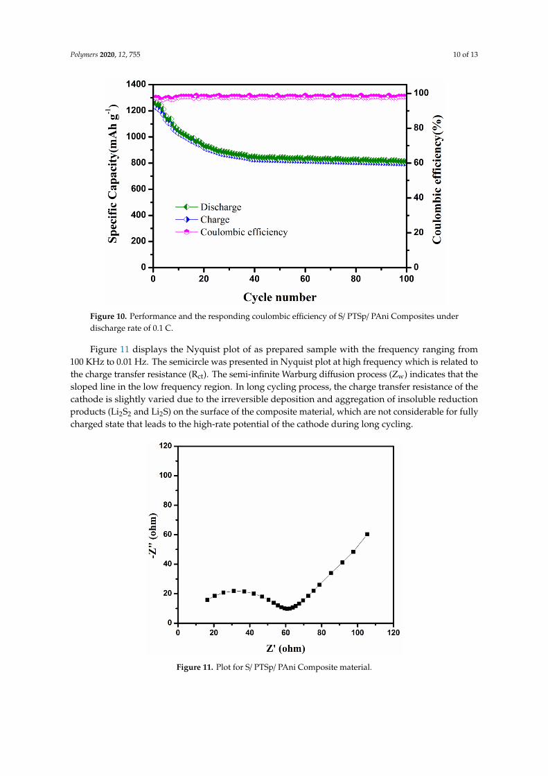
Figure 10 shows the coulombic efficiency of S/PTSp/PAni cathode at a current density of 0.02 C.The cell exhibited a high and stable coulombic efficiency of 97% at its 40 cycles was obtained fromcomposite material. The insignificant loss of active material due to the lithium polysulfide dissolutionprevents shuttling mechanism during discharging processes [43]. This efficiency shows a goodreversible electrochemical performance of the cathode material at high sulfur loading, implying that theunited effect of volume expansion and porosity of the post-treated sepiolite and chemical functioningof PAni are the most importance factors, and this cathode has high potential to be applied to the batteryapplication [44].
Polymers 2020, 12, 755 10 of 13Polymers 2019, 11, x FOR PEER REVIEW 11 of 14
Figure 10. Performance and the responding coulombic efficiency of S/ PTSp/ PAni Composites under
discharge rate of 0.1C.
Figure 10 shows the coulombic efficiency of S/PTSp/PAni cathode at a current density of 0.02 C.
The cell exhibited a high and stable coulombic efficiency of 97% at its 40 cycles was obtained from
composite material. The insignificant loss of active material due to the lithium polysulfide dissolution
prevents shuttling mechanism during discharging processes [43]. This efficiency shows a good
reversible electrochemical performance of the cathode material at high sulfur loading, implying that
the united effect of volume expansion and porosity of the post‐treated sepiolite and chemical
functioning of PAni are the most importance factors, and this cathode has high potential to be applied
to the battery application [44].
Figure 11. Plot for S/ PTSp/ PAni Composite material.
Figure 10. Performance and the responding coulombic efficiency of S/ PTSp/ PAni Composites underdischarge rate of 0.1 C.
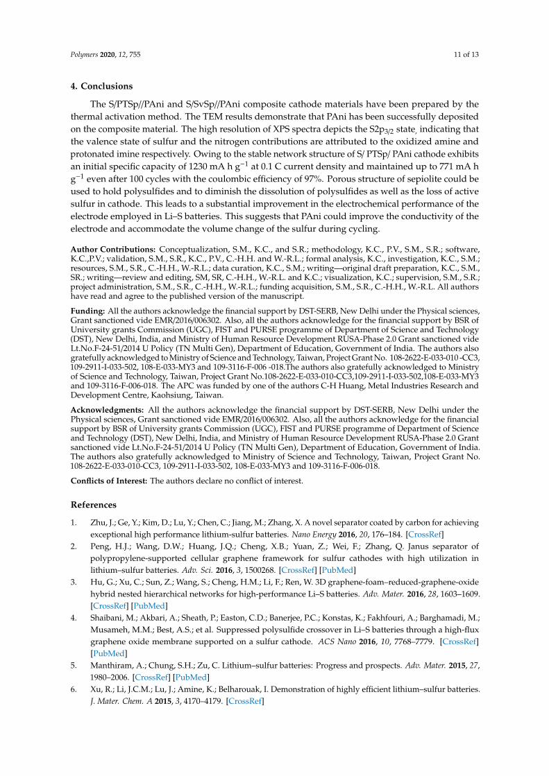
Figure 11 displays the Nyquist plot of as prepared sample with the frequency ranging from100 KHz to 0.01 Hz. The semicircle was presented in Nyquist plot at high frequency which is related tothe charge transfer resistance (Rct). The semi-infinite Warburg diffusion process (Zw) indicates that thesloped line in the low frequency region. In long cycling process, the charge transfer resistance of thecathode is slightly varied due to the irreversible deposition and aggregation of insoluble reductionproducts (Li2S2 and Li2S) on the surface of the composite material, which are not considerable for fullycharged state that leads to the high-rate potential of the cathode during long cycling.
Polymers 2019, 11, x FOR PEER REVIEW 11 of 14
Figure 10. Performance and the responding coulombic efficiency of S/ PTSp/ PAni Composites under
discharge rate of 0.1C.
Figure 10 shows the coulombic efficiency of S/PTSp/PAni cathode at a current density of 0.02 C.
The cell exhibited a high and stable coulombic efficiency of 97% at its 40 cycles was obtained from
composite material. The insignificant loss of active material due to the lithium polysulfide dissolution
prevents shuttling mechanism during discharging processes [43]. This efficiency shows a good
reversible electrochemical performance of the cathode material at high sulfur loading, implying that
the united effect of volume expansion and porosity of the post‐treated sepiolite and chemical
functioning of PAni are the most importance factors, and this cathode has high potential to be applied
to the battery application [44].
Figure 11. Plot for S/ PTSp/ PAni Composite material. Figure 11. Plot for S/ PTSp/ PAni Composite material.
Polymers 2020, 12, 755 11 of 13
4. Conclusions
The S/PTSp//PAni and S/SvSp//PAni composite cathode materials have been prepared by thethermal activation method. The TEM results demonstrate that PAni has been successfully depositedon the composite material. The high resolution of XPS spectra depicts the S2p3/2 state, indicating thatthe valence state of sulfur and the nitrogen contributions are attributed to the oxidized amine andprotonated imine respectively. Owing to the stable network structure of S/ PTSp/ PAni cathode exhibitsan initial specific capacity of 1230 mA h g−1 at 0.1 C current density and maintained up to 771 mA hg−1 even after 100 cycles with the coulombic efficiency of 97%. Porous structure of sepiolite could beused to hold polysulfides and to diminish the dissolution of polysulfides as well as the loss of activesulfur in cathode. This leads to a substantial improvement in the electrochemical performance of theelectrode employed in Li–S batteries. This suggests that PAni could improve the conductivity of theelectrode and accommodate the volume change of the sulfur during cycling.
Author Contributions: Conceptualization, S.M., K.C., and S.R.; methodology, K.C., P.V., S.M., S.R.; software,K.C.,P.V.; validation, S.M., S.R., K.C., P.V., C.-H.H. and W.-R.L.; formal analysis, K.C., investigation, K.C., S.M.;resources, S.M., S.R., C.-H.H., W.-R.L.; data curation, K.C., S.M.; writing—original draft preparation, K.C., S.M.,SR.; writing—review and editing, SM, SR, C.-H.H., W.-R.L. and K.C.; visualization, K.C.; supervision, S.M., S.R.;project administration, S.M., S.R., C.-H.H., W.-R.L.; funding acquisition, S.M., S.R., C.-H.H., W.-R.L. All authorshave read and agree to the published version of the manuscript.
Funding: All the authors acknowledge the financial support by DST-SERB, New Delhi under the Physical sciences,Grant sanctioned vide EMR/2016/006302. Also, all the authors acknowledge for the financial support by BSR ofUniversity grants Commission (UGC), FIST and PURSE programme of Department of Science and Technology(DST), New Delhi, India, and Ministry of Human Resource Development RUSA-Phase 2.0 Grant sanctioned videLt.No.F-24-51/2014 U Policy (TN Multi Gen), Department of Education, Government of India. The authors alsogratefully acknowledged to Ministry of Science and Technology, Taiwan, Project Grant No. 108-2622-E-033-010 -CC3,109-2911-I-033-502, 108-E-033-MY3 and 109-3116-F-006 -018.The authors also gratefully acknowledged to Ministryof Science and Technology, Taiwan, Project Grant No.108-2622-E-033-010-CC3,109-2911-I-033-502,108-E-033-MY3and 109-3116-F-006-018. The APC was funded by one of the authors C-H Huang, Metal Industries Research andDevelopment Centre, Kaohsiung, Taiwan.
Acknowledgments: All the authors acknowledge the financial support by DST-SERB, New Delhi under thePhysical sciences, Grant sanctioned vide EMR/2016/006302. Also, all the authors acknowledge for the financialsupport by BSR of University grants Commission (UGC), FIST and PURSE programme of Department of Scienceand Technology (DST), New Delhi, India, and Ministry of Human Resource Development RUSA-Phase 2.0 Grantsanctioned vide Lt.No.F-24-51/2014 U Policy (TN Multi Gen), Department of Education, Government of India.The authors also gratefully acknowledged to Ministry of Science and Technology, Taiwan, Project Grant No.108-2622-E-033-010-CC3, 109-2911-I-033-502, 108-E-033-MY3 and 109-3116-F-006-018.
Conflicts of Interest: The authors declare no conflict of interest.
References
1. Zhu, J.; Ge, Y.; Kim, D.; Lu, Y.; Chen, C.; Jiang, M.; Zhang, X. A novel separator coated by carbon for achievingexceptional high performance lithium-sulfur batteries. Nano Energy 2016, 20, 176–184. [CrossRef]
2. Peng, H.J.; Wang, D.W.; Huang, J.Q.; Cheng, X.B.; Yuan, Z.; Wei, F.; Zhang, Q. Janus separator ofpolypropylene-supported cellular graphene framework for sulfur cathodes with high utilization inlithium–sulfur batteries. Adv. Sci. 2016, 3, 1500268. [CrossRef] [PubMed]
3. Hu, G.; Xu, C.; Sun, Z.; Wang, S.; Cheng, H.M.; Li, F.; Ren, W. 3D graphene-foam–reduced-graphene-oxidehybrid nested hierarchical networks for high-performance Li–S batteries. Adv. Mater. 2016, 28, 1603–1609.[CrossRef] [PubMed]
4. Shaibani, M.; Akbari, A.; Sheath, P.; Easton, C.D.; Banerjee, P.C.; Konstas, K.; Fakhfouri, A.; Barghamadi, M.;Musameh, M.M.; Best, A.S.; et al. Suppressed polysulfide crossover in Li–S batteries through a high-fluxgraphene oxide membrane supported on a sulfur cathode. ACS Nano 2016, 10, 7768–7779. [CrossRef][PubMed]
5. Manthiram, A.; Chung, S.H.; Zu, C. Lithium–sulfur batteries: Progress and prospects. Adv. Mater. 2015, 27,1980–2006. [CrossRef] [PubMed]
6. Xu, R.; Li, J.C.M.; Lu, J.; Amine, K.; Belharouak, I. Demonstration of highly efficient lithium–sulfur batteries.J. Mater. Chem. A 2015, 3, 4170–4179. [CrossRef]
Polymers 2020, 12, 755 12 of 13
7. Rosenman, A.; Markevich, E.; Salitra, G.; Aurbach, D.; Garsuch, A.; Chesneau, F.F. Review on Li-Sulfurbattery systems: An integral perspective. Adv. Energy Mater. 2015, 5, 16. [CrossRef]
8. Jozwiuk, A.; Berkes, B.B.; Wei, T.; Sommer, H.; Janek, J.; Brezesinski, T. The critical role of lithium nitrate inthe gas evolution of lithium–sulfur batteries. Energy Environ. Sci. 2016, 9, 2603–2608. [CrossRef]
9. Chung, S.H.; Manthiram, A. Bifunctional separator with a light-weight carbon-coating for dynamically andstatically stable Lithium-Sulfur batteries. Adv. Funct. Mater. 2014, 24, 5299–5306. [CrossRef]
10. Nair, J.R.; Bella, F.; Angulakshmi, N.; Stephan, A.M.; Gerbaldi, C. Nanocellulose-laden composite polymerelectrolytes for high performing lithium–sulphur batteries. Energy Storage Mater. 2016, 3, 69–76. [CrossRef]
11. Ji, X.; Lee, K.T.; Nazar, L.F. A highly ordered nanostructured carbon–sulphur cathode for lithium–sulphurbatteries. Nat. Mater. 2009, 8, 500–506. [CrossRef]
12. Lacey, M.J.; Jeschull, F.; Edstrom, K.; Brandell, D. Porosity blocking in highly porous carbon black by PVDFbinder and its implications for the Li–S system. J. Phys. Chem. C 2014, 118, 25890–25898. [CrossRef]
13. Yang, Y.; Zheng, G.; Cui, Y. Nanostructured sulfur cathodes. Chem. Soc. Rev. 2013, 42, 3018–3032. [CrossRef][PubMed]
14. Galan, E. Properties and applications of palygorskite-sepiolite clays. Clay Miner. 1996, 31, 443–454. [CrossRef]15. Alvarez, A. Sepiolite:Properties and uses. Dev. Sedimentol. 1984, 37, 253–287.16. Bokobza, L.; Burr, A.; Garnaud, G.; Perrin, M.Y.; Pagnotta, S. Fibre reinforcement of elastomers:
Nanocomposites based on sepiolite and poly (hydroxyethyl acrylate). Polym. Int. 2004, 53, 1060–1065.[CrossRef]
17. Wang, J.L.; Yang, J.; Xie, J.Y.; Xu, N.X. A novel conductive polymer–sulfur composite cathode material forrechargeable lithium batteries. Adv. Mater. 2002, 14, 963. [CrossRef]
18. Wang, J.; Yang, J.; Wan, C.; Du, K.; Xie, J.; Xu, N. Sulfur composite cathode materials for rechargeable lithiumbatteries. Adv. Funct. Mater. 2003, 13, 487. [CrossRef]
19. Hyun, J.E.; Lee, P.C.; Tatsumi, I. Preparation and electrochemical properties of sulfur-polypyrrole compositecathodes for electric vehicle applications. Electrochim. Acta 2015, 176, 887. [CrossRef]
20. Manthiram, A.; Fu, Y.; Chung, S.H.; Zu, C.; Su, Y.S. Rechargeable lithium–sulfur batteries. Chem. Rev. 2014,114, 11751–11787. [CrossRef]
21. Nicolas-Debarnot, D.; Poncin-Epaillard, F. Polyaniline as a new sensitive layer for gas sensors. Anal. Chim.Acta 2003, 475, 1–15. [CrossRef]
22. Zhou, W.; Yu, Y.; Chen, H.; DiSalvo, J.F.; Abruña, D.H. Yolk–shell structure of polyaniline-coated sulfur forlithium–sulfur batteries. J. Am. Chem. Soc. 2013, 135, 16736. [CrossRef] [PubMed]
23. Yuan, G.; Pan, J.; Zhang, Y.; Yu, J.; Su, Y. Sepiolite/CNT/S @ PAni composite with stable network structure forlithium-sulfur batteries. RSC Adv. 2018, 8, 17950–17957. [CrossRef]
24. Wu, F.; Chen, J.; Li, L.; Zhao, T.; Chen, R. Improvement of rate and cycle performence by rapid polyanilinecoating of a MWCNT/sulfur cathode. J. Phys. Chem. C 2011, 115, 24411. [CrossRef]
25. Ratheesh, R.; Viswanathan, K. Determination of electron and hole effective masses in thermal oxide utilizingan n-channel silicon MOSFET. IOSR J. Appl. Phys. 2014, 6, 2278–4861.
26. Chang, C.H.; Chung, S.H.; Manthiram, A. Ultra-lightweight PANiNF/MWCNT-functionalized separatorswith synergistic suppression of polysulfide migration for Li–S batteries with pure sulfur cathodes. J. Mater.Chem. A 2015, 3, 18829–18834. [CrossRef]
27. Liang, X.; Xu, Y.; Sun, G.; Wang, L.; Sun, Y.; Yang, S.; Xu, Q. Preparation and characterization of mercaptofunctionalized sepiolite and their application for sorption of lead and cadmium. Chem. Eng. J. 2011, 174, 436.[CrossRef]
28. Kellenberger, A.; Dmitrieva, E.; Dunsch, L. The stabilization of charged states at phenazine-like units inpolyaniline under p-doping: An in situ ATR-FTIR spectroelectrochemical study. Phys. Chem. Chem. Phys.2011, 13, 3411–3420. [CrossRef]
29. Trchova, M.; Matejka, P.; Brodinova, J.; Kalendovac, A.; Prokesd, J.; Stejskal, J. Structural and conductivitychanges during the pyrolysis of polyaniline base. Polym. Degrad. Stab. 2006, 91, 114–121. [CrossRef]
30. Barchasz, C.; Molton, F.; Duboc, C.; Lepretre, J.C.; Patoux, S.; Alloin, F. Lithium/sulfur cell dischargemechanism: An original approach for intermediate species identification. Anal. Chem. 2012, 84, 3973–3980.[CrossRef]
31. Jin, L.; Huang, X.; Zeng, G.; Wu, H.; Morbidelli, M. Conductive framework of inverse opal structure forsulfur cathode in lithium-sulfur batteries. Sci. Rep. 2016, 6, 32800. [CrossRef] [PubMed]
Polymers 2020, 12, 755 13 of 13
32. Zhang, Z.; Kong, L.L.; Liu, S.; Li, G.R.; Gao, X.P. A High-Efficiency Sulfur/Carbon Composite Based on 3DGraphene Nanosheet@ Carbon Nanotube Matrix as Cathode for Lithium–Sulfur Battery. Adv. Eng. Mater.2017, 7, 1602543. [CrossRef]
33. Xie, K.; Wei, W.; Yuan, K.; Lu, W.; Guo, W.; Li, Z.; Song, Q.; Liu, X.; Wang, J.G.; Shen, C. Towards dendrite-freelithium deposition via structural and interfacial synergistic effects of 3D graphene@ Ni scaffold. ACS Appl.Mater. Interf. 2016, 8, 26091–26097. [CrossRef] [PubMed]
34. He, X.; Pu, W.; Ren, J.; Wang, L.; Wang, J.; Jiang, C.; Wan, C. Charge/discharge characteristics of sulfurcomposite cathode materials in rechargeable lithium batteries. Electrochim. Acta 2007, 52, 7372–7376.[CrossRef]
35. Choi, Y.J.; Kim, K.W.; Ahn, H.J. Improvement of cycle property of sulfur electrode for lithium/sulfur battery.J. Alloys Compd. 2008, 449, 313–316. [CrossRef]
36. Cheon, S.E.; Ko, K.S.; Cho, J.H.; Kim, S.W.; Chin, E.Y.; Kim, H.T. Rechargeable lithium sulfur battery I.Structural change of sulfur cathode during discharge and charge. J. Electrochem. Soc. 2003, 150, A796–A799.[CrossRef]
37. Rajkumar, P.; Diwakar, K.; Radhika, G.; Krishnaveni, K.; Subadevi, R.; Sivakumar, M. Effect of silicon dioxidein sulfur/carbon black composite as a cathode material for lithium sulfur batteries. Vacuum 2019, 161, 37–48.[CrossRef]
38. Zhou, G.; Wang, D.W.; Li, F.; Hou, P.X.; Yin, L.; Liu, C.; Lu, G.Q.; Gentle, I.R.; Cheng, H.M. Aflexible nanostructured sulphur–carbon nanotube cathode with high rate performance for Li-S batteries.Energy Environ. Sci. 2012, 5, 8901–8906. [CrossRef]
39. Ji, L.; Rao, M.; Zheng, H.; Zhang, L.; Li, Y.; Duan, W.; Guo, J.; Cairns, E.J.; Zhang, Y. Graphene oxide asa sulfur immobilizer in high performance lithim/sulfur cells. J. Am. Chem. Soc. 2011, 133, 18522–18525.[CrossRef]
40. Sun, M.; Zhang, S.; Jiang, T.; Zhang, L.; Yu, J. Nano-wire networks of sulfur–polypyrrole composite cathodematerials for rechargeable lithium batteries. Electrochem. Commun. 2008, 10, 1819–1822. [CrossRef]
41. Li, X.; Zhu, Q.; Guo, W.; Lu, Q. The catalytic activity of manganese dioxide supported on graphene promotingthe electrochemical performance of lithium-sulfur batteries. J. Electroanal. Chem. 2019, 840, 144–152.
42. Li, Y.; Zhang, J.; Liu, X.; Guo, J.; Pan, L.; Wang, H.; Su, Q.; Du, G. Nanosulfur/polyaniline/graphene compositesfor high-performance lithium–sulfur batteries: One pot in-situ synthesis. Mater. Lett. 2014, 133, 193–196.[CrossRef]
43. Li, G.C.; Li, G.R.; Ye, S.H.; Gao, X.P. A polyaniline-coated sulfur/carbon composite with an enhanced high-ratecapability as a cathode material for lithium/sulfur batteries. Adv. Energy Mater. 2012, 2, 1238–1245. [CrossRef]
44. Sohn, H.; Gordin, M.L.; Regula, M.; Kim, D.H.; Jung, Y.S.; Song, J.; Wang, D. Porous sphericalpolyacrylonitrile-carbon nanocomposite with high loading of sulfur for lithium–sulfur batteries. J. PowerSources 2016, 302, 70–78. [CrossRef]
© 2020 by the authors. Licensee MDPI, Basel, Switzerland. This article is an open accessarticle distributed under the terms and conditions of the Creative Commons Attribution(CC BY) license (http://creativecommons.org/licenses/by/4.0/).