Embed Size (px)
Citation preview
Research ArticleEffect of Propane and NaCl-SDS Solution on Nucleation Processof Mine Gas Hydrate
Qiang Zhang,1,2 QiangWu,2 and Hui Zhang1
1College of Material Science and Engineering, Harbin University of Science and Technology, Harbin 150080, China2Department of Safety Engineering, Heilongjiang University of Science & Technology, Harbin 150022, China
Correspondence should be addressed to Hui Zhang; hust [email protected]
Received 5 May 2017; Accepted 13 July 2017; Published 15 August 2017
Academic Editor: Jin Shang
Copyright © 2017 Qiang Zhang et al. This is an open access article distributed under the Creative Commons Attribution License,which permits unrestricted use, distribution, and reproduction in any medium, provided the original work is properly cited.
In order to explore the method of accelerating hydration separation process to recover methane from mine gas, propane hydratephase equilibrium was used to measure the equilibrium points of three kinds of mine gas in NaCl solution. Driving force wasset as 1MPa on this basis and high-pressure experimental apparatus of mine gas hydrate was used to carry out the nucleationkinetics experiments of mine gas hydrate for three gas samples in different concentrations of sodium chloride (NaCl) and sodiumdodecyl sulfate (SDS) compound systems, which was to study the effect of propane and NaCl-SDS solution on nucleation processof mine gas hydrate. The results showed that induction time of multicomponent mine gas hydrate formation was shortened withthe decrease of methane concentration and increase of propane concentration. The induction time of mine gas hydrate formationwas shortened with the reduction of NaCl concentration and the increase of SDS concentration. It was found that methane andpropane in multicomponent mine gas nucleated collaboratively, which simplified its nucleation process compared with the singlecomponent. NaCl has two kinds of functions.
1. Introduction
Methane (CH4) is the main component of mine gas, which
is an ideal gas fuel. It is colorless and tasteless and itspure calorific value is 34000KJ per cubic meter. Methanecombustion mainly produces carbon dioxide and water. Thepollution generated by its combustion only takes up 1/40 thatof oil and 1/800 that of coal in general [1]. As a result, methaneis regarded as themost realistic and reliable safe energywhichis also clean and with high quality. It is reported by EnergyBusiness that the global methane gas resources buried by thedepth of 2000m are about 2400 × 1012m3 [2]. In China, thiskind of resources is estimated to be 36.8 × 10¹²m3, rankingthe third in the world, and the amount of recoverable minegas is about 10 × 1012m3 [3]. From 2010 to 2015, the minegas utilization rate is only 40.91%–46.37% and 46.4 billionm3methane emissions in total during 6 years is equivalent to thatof 94.08 million tons of coal combustion in China [4].
Methane is a kind of strong greenhouse gas with thegreenhouse effect being 21 times than that of CO
2. The
damage to the ozone layer is 7 times that of carbon dioxide[5]. The direct discharge of a large amount of methane notonly causes the waste of resources but also pollutes the atmo-sphere environment. The main reason that a large amountof methane gas cannot be utilized and is directly dischargedis that the methane concentration in the extraction minegas is relatively low and the lack of methane separation andpurification technology as well [6]. Mr. Wu et al. proposedthat methane could be separated and recovered from extrac-tion mine gas by the method of hydration. The mechanismis that the main components of extraction mine gas aremethane, nitrogen, and oxygen and the three kinds of gascan form hydrate, respectively, at a certain temperature andpressure conditions. However, under the same temperature,the pressure of hydrate formation for three gases is extremelydifferent. When it is 273.15 K, the phase equilibrium pressureof methane is 3MPa, nitrogen is 14MPa, and oxygen is11MPa. Therefore, the methane hydrate can be formed bycontrolling the pressure to achieve the purpose of separation[7].
HindawiJournal of ChemistryVolume 2017, Article ID 1059109, 12 pageshttps://doi.org/10.1155/2017/1059109
2 Journal of Chemistry
High separation rate is the key to the separation andrecovery of methane from mine gas by the method ofhydration [8]. The main factor that restricts the rate ofhydration separation is that the induction time of hydrationnucleation is longer, so it is necessary to carry out the researchon shortening the hydrate induction time. The mine gashydrate formation in a relatively short time is the key factorin order to meet the needs of industrial production. Thenucleation induction time is too long which becomes themain bottleneck of the application of the hydrate technology.Scholars have carried out the researchwork onhow to shortenthe induction time.The chemical method of adding accelera-tor has the advantages of simple process, wherein the anionicsurfactant sodium dodecyl sulfate (SDS) is more widely used,and the researchwork of SDS has been carried out by scholarsto promote hydrate formation process.
Karaaslan and Mahmut [9] found that the addition ofsuitable surfactant in the reaction system could effectivelyimprove the surface tension of the air-water system, speedup the heating process and mass transfer, and promotehydrate formation. This conclusion was confirmed by theexperimental study of Zhong and Rogers [10] as well. ThenMohammadi et al. [11] studied the influence of SDS andsilver nanoparticles on kinetics conditions of hydrate for-mation. The results showed that the addition of SDS andsilver nanoparticles increased the apparent rate constantlyand the mixture of SDS and silver nanoparticles was mosteffective in enhancing the apparent rate constantly. Link etal. [12] studied the effect of a series of surfactants on thegrowth rate of methane hydrate and gas storage capacityand found that sodium dodecyl sulfate might be the mostsuitable surfactant for methane hydrate formation. Then,SDS-kaolin and THF-SDS compounded systems were foundto improve the formation rate of mine gas hydrate, and itwas better than the superposition of the single additive [13–15], which showed that the compound additives had thecoordinated effect. Based on the research of NaCl in the pro-cess of hydrate formation, it was identified that NaCl mainlyinfluenced the thermodynamic conditions [16–18]. However,some scholars found that low concentration NaCl couldpromote the hydrate formation and shorten the inductiontime [19]. Propane can also form the hydrate under a certaintemperature and pressure condition, and the hydrate phaseequilibrium pressure was lower than that of methane gasunder the same temperature condition. Some scholars carriedout the hydrate formation experiment utilizing the mixtureof methane and propane gas [20, 21], and the mixed gasphase equilibrium parameters and the crystal structure of gashydrate weremeasured. Prado et al. [22] research showed thathydrate formation of methane and propane mixed gas wasfaster, and the amount of hydrate was bigger, which indicatedthat propane can promote the formation of methane hydrate.
To sum up, propane, NaCl, and SDS can improve themethane hydrate nucleation kinetics in certain conditions.However, effect of propane and NaCl-SDS composite systemon the hydrate nucleation has not been reported yet. As aresult, in terms of the mine gas, it is filled with a certainamount of propane gas, and the phase equilibrium experi-ment of mixed gas hydrate in the NaCl system was primarily
conducted. Based on the results above, the thermodynamiccondition was set up and the mixed gas hydrate nucleationkinetics experiments were carried out in the NaCl-SDScompounded system. The effect of different concentrationsof NaCl and SDS on the mixed gas hydrate nucleation wasinvestigated to explore the distribution law of induction timeof mine gas hydrate formation, which helped to analyze themechanismofNaCl-SDS composite solution and improve thebasic theory and method using mine gas hydration separa-tion.
2. Experimental
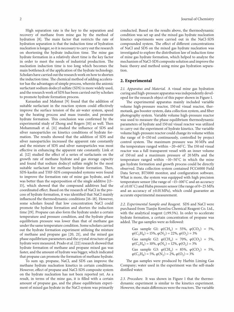
2.1. Apparatus and Material. A visual mine gas hydrationcuring andhigh-pressure apparatuswas independently devel-oped for the research object of this paper shown in Figure 1.
The experimental apparatus mainly included variablevolume high-pressure reactor, 150ml visual reactor, ther-motank, gas booster system, data collection system, and fiberphotography system. Variable volume high-pressure reactorwas used to measure the phase equilibrium thermodynamicparameters of hydrate and 150ml visual reactor was utilizedto carry out the experiment of hydrate kinetics. The variablevolume high-pressure reactor could change its volumewithinthe range of 0∼150ml continuously, controlled by projectcontrol system. The maximum pressure was 30MPa andthe temperature ranged within −20∼60∘C. The 150ml visualreactor was a full transparent vessel with an inner volumeof 150ml and a maximum pressure of 20MPa and thetemperature ranged within −10∼50∘C in which the minegas hydrate formation and growth process could be directlyobserved. Data collection system contained FCC6000 FieldData Server, BT5000 monitor, and configuration software.What is more, the system was equipped with high precisiontemperature sensor (the range of −15∼100∘C and an accuracyof±0.01∘C) andHuba pressure sensor (the range of 0∼25MPaand an accuracy of ±0.01MPa), which could guarantee anaccurate experimental measurement.
2.2. Experimental Sample and Reagent. SDS and NaCl werepurchased from Tianjin Kemi’ou Chemical Reagent Co. Ltd.,with the analytical reagent (≥99.5%). In order to acceleratehydrate formation, a certain concentration of propane wasadded. The gas samples were as followed:
Gas sample G1: 𝜑(CH4) = 55%, 𝜑(CO
2) = 5%,
𝜑(C3H8) = 15%, 𝜑(N
2) = 22%, 𝜑(O
2) = 3%
Gas sample G2: 𝜑(CH4) = 70%, 𝜑(CO
2) = 5%,
𝜑(C3H8) = 10%, 𝜑(N
2) = 12%, 𝜑(O
2) = 3%
Gas sample G3: 𝜑(CH4) = 85%, 𝜑(CO
2) = 5%,
𝜑(C3H8) = 5%, 𝜑(N
2) = 2%, 𝜑(O
2) = 3%
The gas samples were produced by Harbin Liming GasCompany; water used in the experiment was the self-madedistilled water.
2.3. Procedure. It was shown in Figure 1 that the thermo-dynamic experiment is similar to the kinetics experiment.However, themain differences were the reactors.The variable
Journal of Chemistry 3
Stop valve
Gas source
Temperature sensor
Pressure sensor Vacuum pump
Pressure pump
Air compressor Computer
Data acquisition module
Variable volume high-pressure reactor
150ml visual reactor
Figure 1: The systematic diagram of mine gas hydrate’s high-pressure experimental equipment.
volume high-pressure reactor was used in the thermody-namic experiment and the 150ml visual reactor was used inkinetics experiment.
2.3.1. Experiment Method and Procedure of Thermodynamics.(1) The compound solution was prepared containing NaClwith the mass fractions of 0%, 0.5%, 2%, and 3.5% respec-tively.
(2) Firstly, debug the data acquisition software to ensurethe accuracy of the data collected during the experiment.
(3) Put the prepared solution into the experimentalreactor and connect the experimental equipment. Nitrogenwas filled into experimental system until the pressure reached1MPa. Detect the air tightness of system after standing30mins and then the experiment system pressure came to−0.01MPa using the vacuum pump.
(4) The temperature of thermotank was set up as theinitial specified temperature.When the experimental temper-ature reached the initial temperature; the mix gas was filledinto experimental reactor until reaching the initial pressureusing pressurization system.
(5) The space of variable volume reactor was narroweddown by industrial computer to make the pressure increaseuntil hydrate formation. Stop compressing the variable vol-ume reactor and when the pressure within stayed constant,enlarge its space to decrease the pressure. The pressure wasdecreased by 0.2MPa every 5 hours to make the hydratedecomposition. When the hydrate completely decomposed,
the pressure of reactor was increased again and the hydrateformed as well. At the moment, the pressure within was thephase equilibrium pressure under a certain temperature.
(6) According to the above method, three kinds of dif-ferent gas phase equilibrium temperature and pressure weremeasured, and the phase equilibrium curves were recorded.
2.3.2. Experiment Method and Procedure of Kinetics. Quan-tification of hydrate nucleation process was very difficult.First, hydrate nucleationmust be detected. Secondly, in orderto obtain the meaningful average value of the nucleation rate,a large number of nuclear tests were needed. Furthermore,the thermodynamic conditions of the experiment must alsobe controlled.
(1) The compound solution was prepared containingNaCl with the mass fractions of 0%, 0.5%, 2%, and 3.5%respectively, and SDS with the concentration of 0.15, 0.30,0.45, and 0.60mol/L;
(2)–(4) The procedure was the same as the thermody-namics method.
(5) In the condition of constant temperature, the changeof pressure with time was recorded. At the beginning, thepressure decreased constantly due to the dissolution of gasin the liquid phase. When the gas dissolved to become theequilibrium state, the pressure tended to be stable, whichwas recorded as the starting point of induction time andthe ending time was denoted with the formation of hydratecrystal nucleus.
4 Journal of Chemistry
Gas-liquid interface
Hydrate
(a) (b) (c) (d) (e)
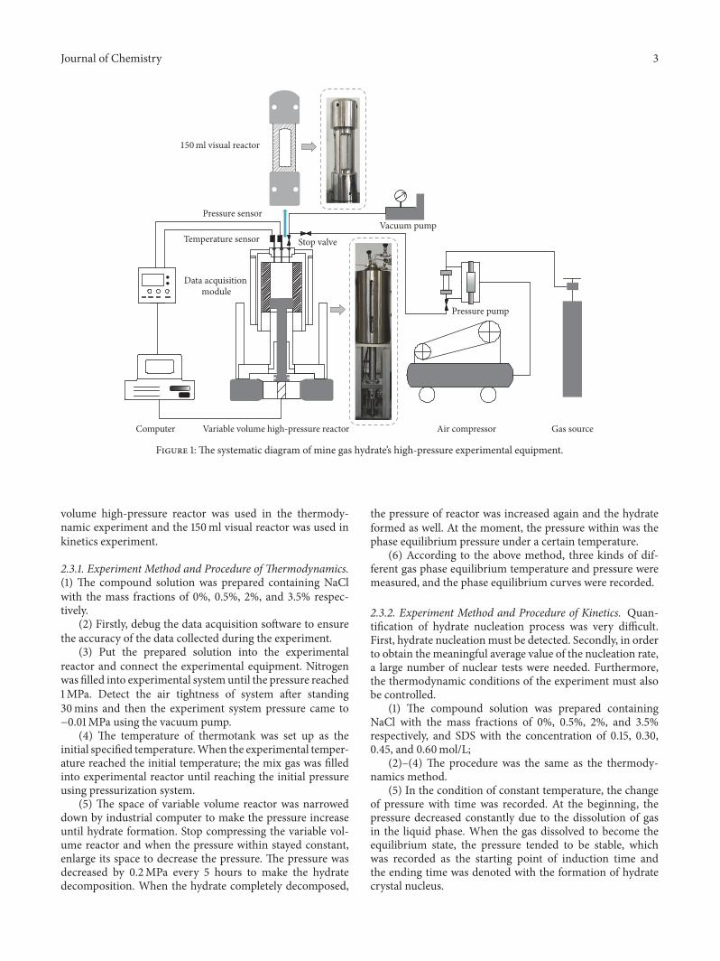
Figure 2: The formation and dissociation process of hydrate. (a) Initial hydrate formation, (b) hydrate growth rapidly, (c) formation endingstage, (d) hydrate decomposition gradually, and (e) hydrate formation for the second time.
(6) The changes of temperature and pressure of hydrateformation and the growth phenomenon were monitored bythe acquisition system and the image recording system.
3. Equilibrium Conditions of Mine GasHydrate Formation in NaCl System
At present, the method of determining the phase equilibriumconditions mainly includes direct observation method, tem-perature searchmethod, quality analysismethod, and graphicmethod [23]. Considering themine gas is a kind ofmixed gas,Tohidi et al. [24] and Schroeter et al. [25] hold that graphicmethod takes a larger error and pressure searchmethod is notsuitable formultisystem and the quality analysismethod has ahigh requirement for the equipment.Therefore, the indepen-dent developed reactor for the multicomponent mixed gashydrate phase equilibrium testing was used to determine theequilibrium parameters incorporating with direct observa-tion method.
Pressure search method is reducing the constant temper-ature gradually until the hydrate formation, and then heatingthe same constant temperature by degrees, the hydratedecomposes gradually with the heating process. Whenthe hydrate is completely decomposed, the temperature isreduced by the certain constant temperature and the hydrateforms. At the moment, the temperature and pressure are thephase equilibrium conditions of hydrate. That is to say, thepressure search method is obtaining the pressure conditionsof hydrate formation by changing temperature. Nevertheless,the author aimed to get the phase equilibrium pressure underthe certain temperature by changing the gas phase volumebased on the pressure search method. The hydrate phaseequilibrium experiment included 72 groups and the hydratechanging process in each group was similar. As a result, takeG1 sample in NaCl system at the temperature of 278.15 Kas an example to explain the hydrate formation and decom-position process in hydrate phase equilibrium experiment.
The initial pressure and temperature are 1MPa and278.15 K. Decreasing the volume of the reactor gradually, thepressure in the reactor was constantly increased. When thepressure was up to 2.1MPa, the hydrate began to generate, asshown in Figure 2(a), and the volume was unchanged. After a
certainmoment, a large number of hydrates formed, as shownin Figure 2(b).Thepressure gradually decreased to 0.8MPa toreach the equilibrium state, as seen in Figure 2(c). Increase thereactor volume gradually to make sure that the pressure wasreduced by 0.1MPa. After every 0.1MPa reduction, six hourswas needed to observe the hydrate.With the pressure decreas-ing gradually, hydrate decomposed, as shown in Figure 2(d).When the hydrate completely decomposed, the volume wascompressed again to ensure the pressure increase by 0.1MPaand the hydrate formed again, as seen in Figure 2(e). Atthe moment, the pressure was 1.17MPa. It is shown thatthe pressure of G1 phase equilibrium under the temperatureof 278.15 K was 1.17MPa. Repeat the above operation andobtain the hydrate phase equilibriumdata of different systemsand different conditions.
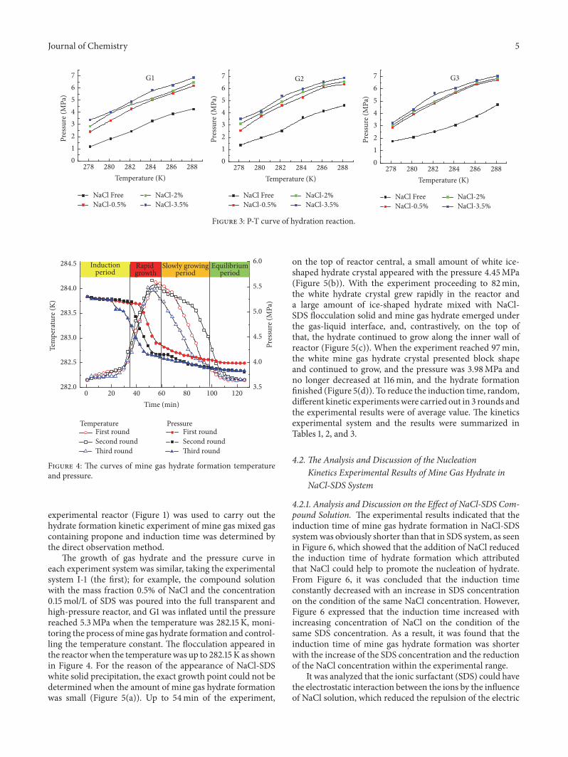
The phase equilibrium results of multicomponent mixedgas hydrate were shown in Figure 3. According to hydratephase equilibrium curve of three kinds of gas, it was foundthat the pressure of hydrate formation becamehigherwith theincrease of NaCl concentration under the same temperature,indicating that NaCl took the inhibitory effect on the forma-tion of gas hydrate. The effect strengthened with the increaseof NaCl concentration. Moreover, in the three kinds of gas inthe same NaCl concentration system, the hydrate phase equi-librium pressure was lower in the gas with higher propaneat the same temperature.
4. Induction Time Distribution of Mine GasHydrate Formation in NaCl-SDS System
4.1. The Mine Gas Hydrate Formation in NaCl-SDS System.NaCl was reported to change the phase equilibrium con-ditions of mine gas hydrate formation by many literatures.However, the purpose of this paper was to investigate theeffect of propane and SDS-NaCl compound system on thenucleation kinetics of mine gas hydrate formation.Therefore,to eliminate the influence of NaCl on the thermodynamiccondition of mine gas mixture hydrates formation, the exper-iment was carried out in the condition of same temperatureand the driving force was 1MPa. The phase equilibriumpressure corresponding to the initial temperature has beenmeasured in Figure 2. In this paper, a fully transparent
Journal of Chemistry 5
G1 G2 G3
01234567
Pres
sure
(MPa
)
01234567
Pres
sure
(MPa
)
01234567
Pres
sure
(MPa
)
280 282 284 286 288278Temperature (K)
280 282 284 286 288278Temperature (K)
280 282 284 286 288278Temperature (K)
NaCl FreeNaCl-0.5%
NaCl-2%NaCl-3.5%
NaCl FreeNaCl-0.5%
NaCl-2%NaCl-3.5%
NaCl FreeNaCl-0.5%
NaCl-2%NaCl-3.5%
Figure 3: P-T curve of hydration reaction.
Inductionperiod
Rapid growth
Slowly growingperiod
Equilibriumperiod
3.5
4.0
4.5
5.0
5.5
6.0Pr
essu
re (M
Pa)
20 40 60 80 100 1200Time (min)
282.0
282.5
283.0
283.5
284.0
284.5
Tem
pera
ture
(K)
TemperatureFirst roundSecond roundThird round
PressureFirst roundSecond roundThird round
Figure 4: The curves of mine gas hydrate formation temperatureand pressure.
experimental reactor (Figure 1) was used to carry out thehydrate formation kinetic experiment of mine gas mixed gascontaining propone and induction time was determined bythe direct observation method.
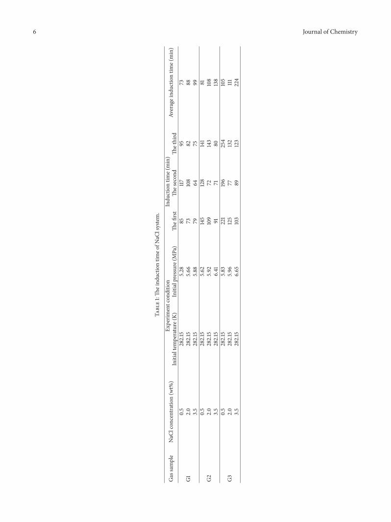
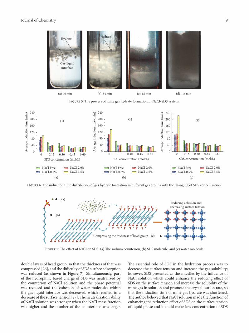
The growth of gas hydrate and the pressure curve ineach experiment system was similar, taking the experimentalsystem I-1 (the first); for example, the compound solutionwith the mass fraction 0.5% of NaCl and the concentration0.15mol/L of SDS was poured into the full transparent andhigh-pressure reactor, and G1 was inflated until the pressurereached 5.3MPa when the temperature was 282.15 K, moni-toring the process ofmine gas hydrate formation and control-ling the temperature constant. The flocculation appeared inthe reactor when the temperaturewas up to 282.15 K as shownin Figure 4. For the reason of the appearance of NaCl-SDSwhite solid precipitation, the exact growth point could not bedetermined when the amount of mine gas hydrate formationwas small (Figure 5(a)). Up to 54min of the experiment,
on the top of reactor central, a small amount of white ice-shaped hydrate crystal appeared with the pressure 4.45MPa(Figure 5(b)). With the experiment proceeding to 82min,the white hydrate crystal grew rapidly in the reactor anda large amount of ice-shaped hydrate mixed with NaCl-SDS flocculation solid and mine gas hydrate emerged underthe gas-liquid interface, and, contrastively, on the top ofthat, the hydrate continued to grow along the inner wall ofreactor (Figure 5(c)). When the experiment reached 97min,the white mine gas hydrate crystal presented block shapeand continued to grow, and the pressure was 3.98MPa andno longer decreased at 116min, and the hydrate formationfinished (Figure 5(d)). To reduce the induction time, random,different kinetic experimentswere carried out in 3 rounds andthe experimental results were of average value. The kineticsexperimental system and the results were summarized inTables 1, 2, and 3.
4.2. The Analysis and Discussion of the NucleationKinetics Experimental Results of Mine Gas Hydrate inNaCl-SDS System
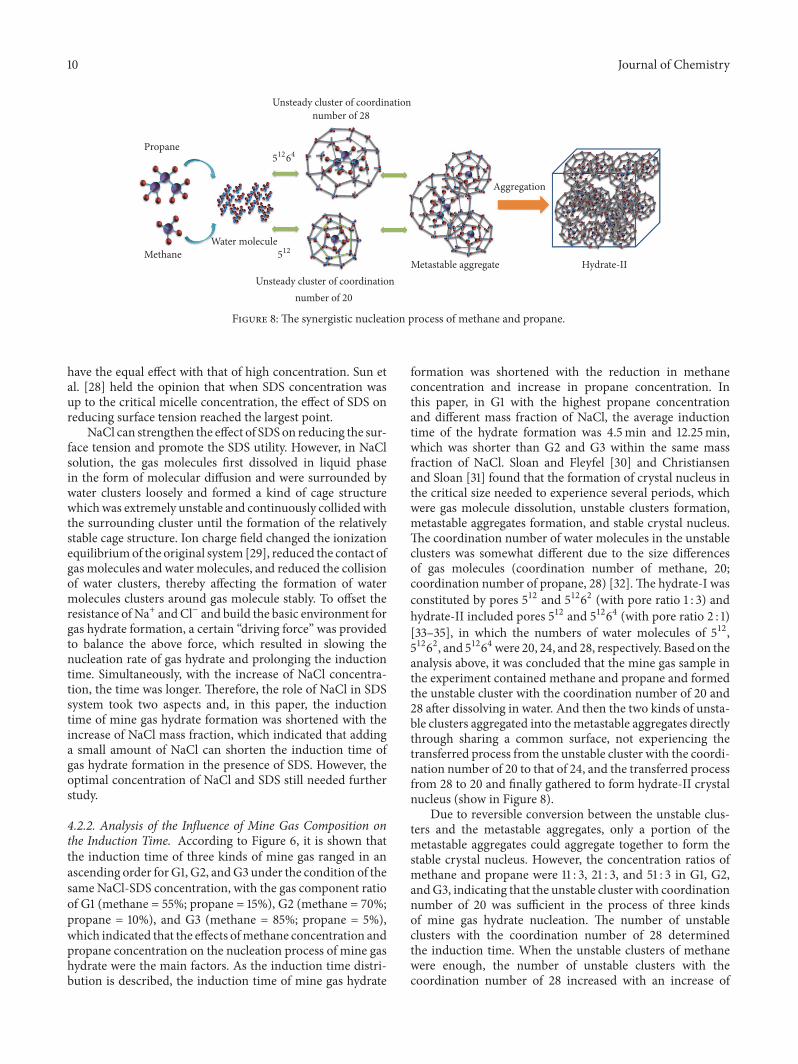
4.2.1. Analysis and Discussion on the Effect of NaCl-SDS Com-pound Solution. The experimental results indicated that theinduction time of mine gas hydrate formation in NaCl-SDSsystemwas obviously shorter than that in SDS system, as seenin Figure 6, which showed that the addition of NaCl reducedthe induction time of hydrate formation which attributedthat NaCl could help to promote the nucleation of hydrate.From Figure 6, it was concluded that the induction timeconstantly decreased with an increase in SDS concentrationon the condition of the same NaCl concentration. However,Figure 6 expressed that the induction time increased withincreasing concentration of NaCl on the condition of thesame SDS concentration. As a result, it was found that theinduction time of mine gas hydrate formation was shorterwith the increase of the SDS concentration and the reductionof the NaCl concentration within the experimental range.
It was analyzed that the ionic surfactant (SDS) could havethe electrostatic interaction between the ions by the influenceof NaCl solution, which reduced the repulsion of the electric
6 Journal of Chemistry
Table1:Th
eind
uctio
ntim
eofN
aClsystem.
Gas
sample
NaC
lcon
centratio
n(w
t%)
Experim
entcon
ditio
nIndu
ctiontim
e(min)
Averageind
uctio
ntim
e(min)
Initialtemperature
(K)
Initialpressure
(MPa)
Thefi
rst
Thes
econ
dTh
ethird
G1
0.5
282.15
5.28
85117
9573
2.0
282.15
5.66
73108
8288
3.5
282.15
5.88
7964
7599
G2
0.5
282.15
5.62
145
128
141
812.0
282.15
5.92
109
72143
108
3.5
282.15
6.41
9171
80138
G3
0.5
282.15
5.83
221
196
254
105
2.0
282.15
5.96
125
77132
111
3.5
282.15
6.65
103
89123
224
Journal of Chemistry 7
Table2:Th
enucleationkinetic
sexp
erim
entalresultsof
mineg
ashydrateinSD
Ssyste
m.
Gas
sample
SDS(m
ol/L)
Experim
entcon
ditio
nIndu
ctiontim
e(min)
Averageind
uctio
ntim
e(min)
Initialpressure
(MPa)
Initialtemperature
(K)
Thefi
rst
Thes
econ
dTh
ethird
G1
0.15
3.43
282.15
4864
7061
0.30
6842
5053
0.45
4134
3436
0.60
2629
3731
G2
0.15
3.51
282.15
5955
7964
0.30
3563
5852
0.45
4244
2537
0.60
2437
4134
G3
0.15
3.52
282.15
7882
4869
0.30
3961
6455
0.45
4442
6550
0.60
3847
5547
8 Journal of Chemistry
Table3:Th
eind
uctio
ntim
eofm
ineg
ashydrateformationin
NaC
l-SDSsyste
m.
Experim
ent
number
Gas
sample
NaC
lcon
cen-
tration
(wt%
)
SDS(m
ol/L)
Experim
entcon
ditio
nIndu
ctiontim
e(min)
Averageind
uctio
ntim
e(m
in)
Initialpressure
(MPa)
Initialtemperature
(K)
Thefi
rst
Thes
econ
dTh
ethird
I-1
G1
0.5%
0.15
5.28
282.15
4338
2335
I-2
0.30
2723
3428
I-3
0.45
2525
1923
I-4
0.60
1711
2618
I-5
2%
0.15
5.66
282.15
3139
4237
I-6
0.30
2434
4033
I-7
0.45
1944
1325
I-8
0.60
2610
4126
I-9
3.5%
0.15
5.88
282.15
5145
2841
I-10
0.30
3541
3838
I-11
0.45
2610
5029
I-12
0.60
1937
2828
II-1
G2
0.5%
0.15
5.62
282.15
3545
3137
II-2
0.30
3441
3035
II-3
0.45
3731
2531
II-4
0.60
2219
3826
II-5
2%
0.15
5.92
282.15
3746
3439
II-6
0.30
4238
3037
II-7
0.45
2933
3733
II-8
0.60
1931
3528
II-9
3.5%
0.15
6.41
282.15
3941
4441
II-10
0.30
3134
5239
II-11
0.45
4139
3438
II-12
0.60
2831
3331
III-1
G3
0.5%
0.15
5.83
282.15
4860
3849
III-2
0.30
5348
3244
III-3
0.45
3539
2934
III-4
0.60
4523
2832
III-5
2%
0.15
5.96
282.15
5555
4652
III-6
0.30
5134
4945
III-7
0.45
3322
5838
III-8
0.60
3920
4234
III-9
3.5%
0.15
6.65
282.15
4847
6252
III-10
0.30
4855
4750
III-11
0.45
4737
3439
III-12
0.60
4822
4839
Journal of Chemistry 9
Hydrate
Gas-liquid interface
(a) 10min
Hydrate
(b) 54min (c) 82min (d) 116min
Figure 5: The process of mine gas hydrate formation in NaCl-SDS system.
G1
SDS concentration (mol/L)
NaCl FreeNaCl-0.5%
NaCl-2.0%NaCl-3.5%
0
40
80
120
160
200
240
Aver
age i
nduc
tion
time (
min
)
0 0.15 0.30 0.45 0.60
(a)
SDS concentration (mol/L)
G2
0
40
80
120
160
200
240
Aver
age i
nduc
tion
time (
min
)
NaCl FreeNaCl-0.5%
NaCl-2.0%NaCl-3.5%
0 0.15 0.30 0.45 0.60
(b)
SDS concentration (mol/L)
G3
0
40
80
120
160
200
240
Aver
age i
nduc
tion
time (
min
)NaCl FreeNaCl-0.5%
NaCl-2.0%NaCl-3.5%
0 0.15 0.30 0.45 0.60
(c)
Figure 6: The induction time distribution of gas hydrate formation in different gas groups with the changing of SDS concentration.
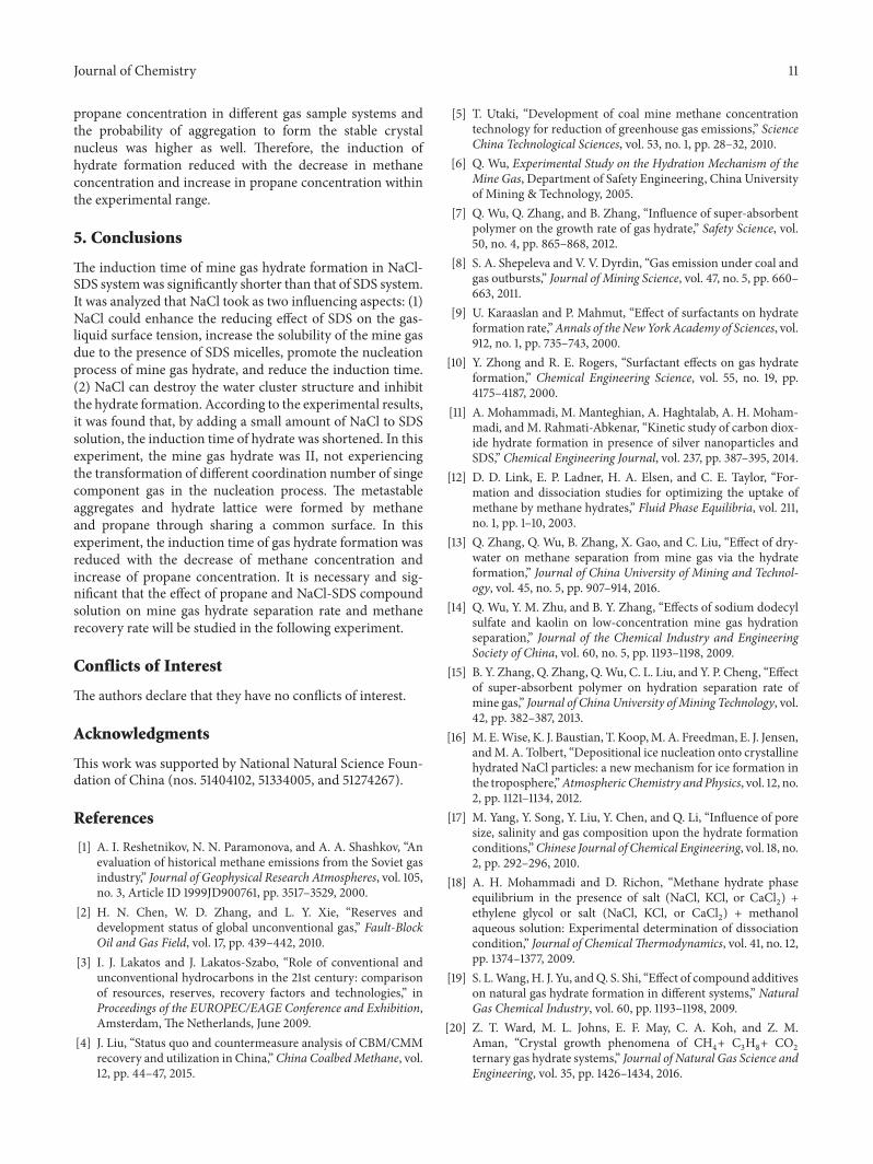
(a)
(b)
(c)Compressing the thickness of head group
Reducing cohesion anddecreasing surface tension
Figure 7: The effect of NaCl on SDS. (a) The sodium counterion, (b) SDS molecule, and (c) water molecule.
double layers of head group, so that the thickness of that wascompressed [26], and the difficulty of SDS surface adsorptionwas reduced (as shown in Figure 7). Simultaneously, partof the hydrophilic based charge of SDS was neutralized bythe counterion of NaCl solution and the phase potentialwas reduced and the cohesion of water molecules withinthe gas-liquid interface was decreased, which resulted in adecrease of the surface tension [27].The neutralization abilityof NaCl solution was stronger when the NaCl mass fractionwas higher and the number of the counterions was larger.
The essential role of SDS in the hydration process was todecrease the surface tension and increase the gas solubility;however, SDS presented as the micelles by the influence ofNaCl solution which could enhance the reducing effect ofSDS on the surface tension and increase the solubility of themine gas in solution and promote the crystallization rate, sothat the induction time of mine gas hydrate was shortened.The author believed that NaCl solution made the function ofenhancing the reduction effect of SDS on the surface tensionof liquid phase and it could make low concentration of SDS
10 Journal of Chemistry
Propane
MethaneWater molecule
51264
512
Unsteady cluster of coordination
Unsteady cluster of coordinationnumber of 28
number of 20
Metastable aggregate
Aggregation
Hydrate-II
Figure 8: The synergistic nucleation process of methane and propane.
have the equal effect with that of high concentration. Sun etal. [28] held the opinion that when SDS concentration wasup to the critical micelle concentration, the effect of SDS onreducing surface tension reached the largest point.
NaCl can strengthen the effect of SDSon reducing the sur-face tension and promote the SDS utility. However, in NaClsolution, the gas molecules first dissolved in liquid phasein the form of molecular diffusion and were surrounded bywater clusters loosely and formed a kind of cage structurewhich was extremely unstable and continuously collided withthe surrounding cluster until the formation of the relativelystable cage structure. Ion charge field changed the ionizationequilibriumof the original system [29], reduced the contact ofgas molecules and water molecules, and reduced the collisionof water clusters, thereby affecting the formation of watermolecules clusters around gas molecule stably. To offset theresistance ofNa+ andCl− and build the basic environment forgas hydrate formation, a certain “driving force” was providedto balance the above force, which resulted in slowing thenucleation rate of gas hydrate and prolonging the inductiontime. Simultaneously, with the increase of NaCl concentra-tion, the time was longer. Therefore, the role of NaCl in SDSsystem took two aspects and, in this paper, the inductiontime of mine gas hydrate formation was shortened with theincrease of NaCl mass fraction, which indicated that addinga small amount of NaCl can shorten the induction time ofgas hydrate formation in the presence of SDS. However, theoptimal concentration of NaCl and SDS still needed furtherstudy.
4.2.2. Analysis of the Influence of Mine Gas Composition onthe Induction Time. According to Figure 6, it is shown thatthe induction time of three kinds of mine gas ranged in anascending order forG1, G2, andG3 under the condition of thesame NaCl-SDS concentration, with the gas component ratioof G1 (methane = 55%; propane = 15%), G2 (methane = 70%;propane = 10%), and G3 (methane = 85%; propane = 5%),which indicated that the effects ofmethane concentration andpropane concentration on the nucleation process of mine gashydrate were the main factors. As the induction time distri-bution is described, the induction time of mine gas hydrate
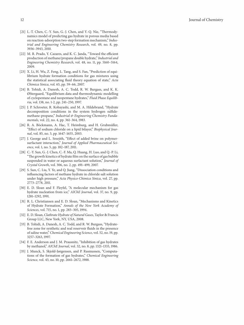
formation was shortened with the reduction in methaneconcentration and increase in propane concentration. Inthis paper, in G1 with the highest propane concentrationand different mass fraction of NaCl, the average inductiontime of the hydrate formation was 4.5min and 12.25min,which was shorter than G2 and G3 within the same massfraction of NaCl. Sloan and Fleyfel [30] and Christiansenand Sloan [31] found that the formation of crystal nucleus inthe critical size needed to experience several periods, whichwere gas molecule dissolution, unstable clusters formation,metastable aggregates formation, and stable crystal nucleus.The coordination number of water molecules in the unstableclusters was somewhat different due to the size differencesof gas molecules (coordination number of methane, 20;coordination number of propane, 28) [32].The hydrate-I wasconstituted by pores 512 and 51262 (with pore ratio 1 : 3) andhydrate-II included pores 512 and 51264 (with pore ratio 2 : 1)[33–35], in which the numbers of water molecules of 512,51262, and 51264 were 20, 24, and 28, respectively. Based on theanalysis above, it was concluded that the mine gas sample inthe experiment contained methane and propane and formedthe unstable cluster with the coordination number of 20 and28 after dissolving in water. And then the two kinds of unsta-ble clusters aggregated into themetastable aggregates directlythrough sharing a common surface, not experiencing thetransferred process from the unstable cluster with the coordi-nation number of 20 to that of 24, and the transferred processfrom 28 to 20 and finally gathered to form hydrate-II crystalnucleus (show in Figure 8).
Due to reversible conversion between the unstable clus-ters and the metastable aggregates, only a portion of themetastable aggregates could aggregate together to form thestable crystal nucleus. However, the concentration ratios ofmethane and propane were 11 : 3, 21 : 3, and 51 : 3 in G1, G2,andG3, indicating that the unstable cluster with coordinationnumber of 20 was sufficient in the process of three kindsof mine gas hydrate nucleation. The number of unstableclusters with the coordination number of 28 determinedthe induction time. When the unstable clusters of methanewere enough, the number of unstable clusters with thecoordination number of 28 increased with an increase of
Journal of Chemistry 11
propane concentration in different gas sample systems andthe probability of aggregation to form the stable crystalnucleus was higher as well. Therefore, the induction ofhydrate formation reduced with the decrease in methaneconcentration and increase in propane concentration withinthe experimental range.
5. Conclusions
The induction time of mine gas hydrate formation in NaCl-SDS systemwas significantly shorter than that of SDS system.It was analyzed that NaCl took as two influencing aspects: (1)NaCl could enhance the reducing effect of SDS on the gas-liquid surface tension, increase the solubility of the mine gasdue to the presence of SDS micelles, promote the nucleationprocess of mine gas hydrate, and reduce the induction time.(2) NaCl can destroy the water cluster structure and inhibitthe hydrate formation. According to the experimental results,it was found that, by adding a small amount of NaCl to SDSsolution, the induction time of hydrate was shortened. In thisexperiment, the mine gas hydrate was II, not experiencingthe transformation of different coordination number of singecomponent gas in the nucleation process. The metastableaggregates and hydrate lattice were formed by methaneand propane through sharing a common surface. In thisexperiment, the induction time of gas hydrate formation wasreduced with the decrease of methane concentration andincrease of propane concentration. It is necessary and sig-nificant that the effect of propane and NaCl-SDS compoundsolution on mine gas hydrate separation rate and methanerecovery rate will be studied in the following experiment.
Conflicts of Interest
The authors declare that they have no conflicts of interest.
Acknowledgments
This work was supported by National Natural Science Foun-dation of China (nos. 51404102, 51334005, and 51274267).
References
[1] A. I. Reshetnikov, N. N. Paramonova, and A. A. Shashkov, “Anevaluation of historical methane emissions from the Soviet gasindustry,” Journal of Geophysical Research Atmospheres, vol. 105,no. 3, Article ID 1999JD900761, pp. 3517–3529, 2000.
[2] H. N. Chen, W. D. Zhang, and L. Y. Xie, “Reserves anddevelopment status of global unconventional gas,” Fault-BlockOil and Gas Field, vol. 17, pp. 439–442, 2010.
[3] I. J. Lakatos and J. Lakatos-Szabo, “Role of conventional andunconventional hydrocarbons in the 21st century: comparisonof resources, reserves, recovery factors and technologies,” inProceedings of the EUROPEC/EAGE Conference and Exhibition,Amsterdam, The Netherlands, June 2009.
[4] J. Liu, “Status quo and countermeasure analysis of CBM/CMMrecovery and utilization in China,”China CoalbedMethane, vol.12, pp. 44–47, 2015.
[5] T. Utaki, “Development of coal mine methane concentrationtechnology for reduction of greenhouse gas emissions,” ScienceChina Technological Sciences, vol. 53, no. 1, pp. 28–32, 2010.
[6] Q. Wu, Experimental Study on the Hydration Mechanism of theMine Gas, Department of Safety Engineering, China Universityof Mining & Technology, 2005.
[7] Q. Wu, Q. Zhang, and B. Zhang, “Influence of super-absorbentpolymer on the growth rate of gas hydrate,” Safety Science, vol.50, no. 4, pp. 865–868, 2012.
[8] S. A. Shepeleva and V. V. Dyrdin, “Gas emission under coal andgas outbursts,” Journal of Mining Science, vol. 47, no. 5, pp. 660–663, 2011.
[9] U. Karaaslan and P. Mahmut, “Effect of surfactants on hydrateformation rate,”Annals of theNewYorkAcademy of Sciences, vol.912, no. 1, pp. 735–743, 2000.
[10] Y. Zhong and R. E. Rogers, “Surfactant effects on gas hydrateformation,” Chemical Engineering Science, vol. 55, no. 19, pp.4175–4187, 2000.
[11] A. Mohammadi, M. Manteghian, A. Haghtalab, A. H. Moham-madi, andM. Rahmati-Abkenar, “Kinetic study of carbon diox-ide hydrate formation in presence of silver nanoparticles andSDS,” Chemical Engineering Journal, vol. 237, pp. 387–395, 2014.
[12] D. D. Link, E. P. Ladner, H. A. Elsen, and C. E. Taylor, “For-mation and dissociation studies for optimizing the uptake ofmethane by methane hydrates,” Fluid Phase Equilibria, vol. 211,no. 1, pp. 1–10, 2003.
[13] Q. Zhang, Q. Wu, B. Zhang, X. Gao, and C. Liu, “Effect of dry-water on methane separation from mine gas via the hydrateformation,” Journal of China University of Mining and Technol-ogy, vol. 45, no. 5, pp. 907–914, 2016.
[14] Q. Wu, Y. M. Zhu, and B. Y. Zhang, “Effects of sodium dodecylsulfate and kaolin on low-concentration mine gas hydrationseparation,” Journal of the Chemical Industry and EngineeringSociety of China, vol. 60, no. 5, pp. 1193–1198, 2009.
[15] B. Y. Zhang, Q. Zhang, Q.Wu, C. L. Liu, and Y. P. Cheng, “Effectof super-absorbent polymer on hydration separation rate ofmine gas,” Journal of China University ofMining Technology, vol.42, pp. 382–387, 2013.
[16] M. E.Wise, K. J. Baustian, T. Koop,M.A. Freedman, E. J. Jensen,andM. A. Tolbert, “Depositional ice nucleation onto crystallinehydrated NaCl particles: a new mechanism for ice formation inthe troposphere,”Atmospheric Chemistry andPhysics, vol. 12, no.2, pp. 1121–1134, 2012.
[17] M. Yang, Y. Song, Y. Liu, Y. Chen, and Q. Li, “Influence of poresize, salinity and gas composition upon the hydrate formationconditions,”Chinese Journal of Chemical Engineering, vol. 18, no.2, pp. 292–296, 2010.
[18] A. H. Mohammadi and D. Richon, “Methane hydrate phaseequilibrium in the presence of salt (NaCl, KCl, or CaCl
2) +
ethylene glycol or salt (NaCl, KCl, or CaCl2) + methanol
aqueous solution: Experimental determination of dissociationcondition,” Journal of ChemicalThermodynamics, vol. 41, no. 12,pp. 1374–1377, 2009.
[19] S. L.Wang,H. J. Yu, andQ. S. Shi, “Effect of compound additiveson natural gas hydrate formation in different systems,” NaturalGas Chemical Industry, vol. 60, pp. 1193–1198, 2009.
[20] Z. T. Ward, M. L. Johns, E. F. May, C. A. Koh, and Z. M.Aman, “Crystal growth phenomena of CH
4+ C3H8+ CO
2
ternary gas hydrate systems,” Journal of Natural Gas Science andEngineering, vol. 35, pp. 1426–1434, 2016.
12 Journal of Chemistry
[21] L.-T. Chen, C.-Y. Sun, G.-J. Chen, and Y.-Q. Nie, “Thermody-namics model of predicting gas hydrate in porous media basedon reaction-adsorption two-step formationmechanism,” Indus-trial and Engineering Chemistry Research, vol. 49, no. 8, pp.3936–3943, 2010.
[22] M. R. Prado, Y. Cazares, and K. C. Janda, “Toward the efficientproduction ofmethane/propane double hydrate,” Industrial andEngineering Chemistry Research, vol. 48, no. 11, pp. 5160–5164,2009.
[23] X. Li, H. Wu, Z. Feng, L. Tang, and S. Fan, “Prediction of equi-librium hydrate formation conditions for gas mixtures usingthe statistical associating fluid theory equation of state,” ActaChimica Sinica, vol. 65, pp. 59–66, 2007.
[24] B. Tohidi, A. Danesh, A. C. Todd, R. W. Burgass, and K. K.ØStergaard, “Equilibrium data and thermodynamic modellingof cyclopentane and neopentane hydrates,” Fluid Phase Equilib-ria, vol. 138, no. 1-2, pp. 241–250, 1997.
[25] J. P. Schroeter, R. Kobayashi, and M. A. Hildebrand, “Hydratedecomposition conditions in the system hydrogen sulfide-methane-propane,” Industrial & Engineering Chemistry Funda-mentals, vol. 22, no. 4, pp. 361–364, 1983.
[26] R. A. Bockmann, A. Hac, T. Heimburg, and H. Grubmuller,“Effect of sodium chloride on a lipid bilayer,” Biophysical Jour-nal, vol. 85, no. 3, pp. 1647–1655, 2003.
[27] J. George and L. Sreejith, “Effect of added brine on polymer-surfactant interaction,” Journal of Applied Pharmaceutical Sci-ence, vol. 1, no. 5, pp. 182–187, 2011.
[28] C.-Y. Sun, G.-J. Chen, C.-F. Ma, Q. Huang, H. Luo, and Q.-P. Li,“The growth kinetics of hydrate filmon the surface of gas bubblesuspended in water or aqueous surfactant solution,” Journal ofCrystal Growth, vol. 306, no. 2, pp. 491–499, 2007.
[29] S. Sun, C. Liu, Y. Ye, and Q. Jiang, “Dissociation conditions andinfluencing factors of methane hydrate in chloride salt solutionunder high pressure,” Acta Physico-Chimica Sinica, vol. 27, pp.2773–2778, 2011.
[30] E. D. Sloan and F. Fleyfel, “A molecular mechanism for gashydrate nucleation from ice,” AIChE Journal, vol. 37, no. 9, pp.1281–1292, 1991.
[31] R. L. Christiansen and E. D. Sloan, “Mechanisms and Kineticsof Hydrate Formation,” Annals of the New York Academy ofSciences, vol. 715, no. 1, pp. 283–305, 1994.
[32] E. D. Sloan,ClathrateHydrate of Natural Gases, Taylor& FrancisGroup LLC, New York, NY, USA, 2008.
[33] B. Tohidi, A. Danesh, A. C. Todd, and R. W. Burgass, “Hydrate-free zone for synthetic and real reservoir fluids in the presenceof saline water,”Chemical Engineering Science, vol. 52, no. 19, pp.3257–3263, 1997.
[34] F. E. Anderson and J. M. Prausnitz, “Inhibition of gas hydratesby methanol,” AIChE Journal, vol. 32, no. 8, pp. 1321–1333, 1986.
[35] J. Munck, S. Skjold-Jørgensen, and P. Rasmussen, “Computa-tions of the formation of gas hydrates,” Chemical EngineeringScience, vol. 43, no. 10, pp. 2661–2672, 1988.
Submit your manuscripts athttps://www.hindawi.com
Hindawi Publishing Corporationhttp://www.hindawi.com Volume 2014
Inorganic ChemistryInternational Journal of
Hindawi Publishing Corporation http://www.hindawi.com Volume 201
International Journal ofInternational Journal ofPhotoenergy
Hindawi Publishing Corporationhttp://www.hindawi.com Volume 2014
Carbohydrate Chemistry
International Journal ofInternational Journal of
Hindawi Publishing Corporationhttp://www.hindawi.com Volume 2014
Journal of
Chemistry
Hindawi Publishing Corporationhttp://www.hindawi.com Volume 2014
Advances in
Physical Chemistry
Hindawi Publishing Corporationhttp://www.hindawi.com
Analytical Methods in Chemistry
Journal of
Volume 2014
Bioinorganic Chemistry and ApplicationsHindawi Publishing Corporationhttp://www.hindawi.com Volume 2014
SpectroscopyInternational Journal of
Hindawi Publishing Corporationhttp://www.hindawi.com Volume 2014
The Scientific World JournalHindawi Publishing Corporation http://www.hindawi.com Volume 2014
Medicinal ChemistryInternational Journal of
Hindawi Publishing Corporationhttp://www.hindawi.com Volume 2014
Chromatography Research International
Hindawi Publishing Corporationhttp://www.hindawi.com Volume 2014
Applied ChemistryJournal of
Hindawi Publishing Corporationhttp://www.hindawi.com Volume 2014
Hindawi Publishing Corporationhttp://www.hindawi.com Volume 2014
Theoretical ChemistryJournal of
Hindawi Publishing Corporationhttp://www.hindawi.com Volume 2014
Journal of
Spectroscopy
Analytical ChemistryInternational Journal of
Hindawi Publishing Corporationhttp://www.hindawi.com Volume 2014
Journal of
Hindawi Publishing Corporationhttp://www.hindawi.com Volume 2014
Quantum Chemistry
Hindawi Publishing Corporationhttp://www.hindawi.com Volume 2014
Organic Chemistry International
ElectrochemistryInternational Journal of
Hindawi Publishing Corporation http://www.hindawi.com Volume 2014
Hindawi Publishing Corporationhttp://www.hindawi.com Volume 2014
CatalystsJournal of
![Temperature‐dependent Nucleation and Growth of Dendrite‐Free … · nucleation, chronoamperometry has been used to model heterogeneous nucleation behavior.[10] Therefore, we further](https://img.pdfslide.net/doc/110x75/5ecedb8e0e2bd5210370ca09/temperatureadependent-nucleation-and-growth-of-dendriteafree-nucleation-chronoamperometry.jpg)