Embed Size (px)
Citation preview
Available online at www.pelagiaresearchlibrary.com
Pelagia Research Library
Advances in Applied Science Research, 2015, 6(8):134-147
ISSN: 0976-8610 CODEN (USA): AASRFC
134 Pelagia Research Library
Effect of soil stabilizers on the structural design of flexible pavements
Vivek Singh Pundir* and Ved Prakash
Department of Civil Engineering, Geeta Institute of Management & Technology, Haryana, India _____________________________________________________________________________________________
ABSTRACT Poor sub grade soil conditions can result in inadequate pavement support and reduce pavement life. Soils may be improved through the addition of chemical or cementations additives. These chemical additives range from waste products to manufactured materials and include lime, Class C fly ash, Portland cement, cement kiln dust, RBI Grade 81. These additives can be used with a variety of soils to help improve their native engineering properties. The effectiveness of these additives depends on the soil treated and the amount of additive used. Design of the various pavement layers is very much dependent on the strength of the sub grade soil over which they are going to be laid. The sub grade strength is mostly expressed in terms of Indian Bearing Ratio (IBR). Weaker sub grade essentially requires thicker layers whereas stronger sub grade goes well with thinner pavement layers. The pavement and the sub grade mutually must sustain the traffic volume. The Indian Road Congress (IRC) encodes the exact design strategies of the pavement layers based upon the sub grade strength which is primarily dependant on IBR value for a laboratory or field sample soaked for four days. For an engineer, it’s important to understand the change of sub grade strength. This project is an attempt to understand the strength of sub grade in terms of IBR values subjected to different types of stabilizers. Treatment with cement and lime was found to be an effective option for improvement of soil properties, based on the testing conducted as a part of this work. It was found that with the addition of stabilizers i.e. cement and lime, the I.B.R. increased upto a certain limit but after that the I.B.R. decreased even on the further addition of stabilizers. Key words: Soil Stabilization, Lime, Port land cement, RBI Grade-81, IBR and MDD. _____________________________________________________________________________________________
INTRODUCTION Soil Stabilization has proved to be very economical as it provides cheap materials for the construction of low cost roads. Local materials can be used effectively. There are many techniques of soil stabilization. Cement stabilization is an important method of stabilization. it has proved very much effective in case of sandy soil due to the ease of pulverization and mixing and the smaller quantity of cement required. Cement stabilization refers to stabilizing soils with Portland cement. The primary reaction is with the water in the soil that leads to the formation of a cementitiuos material (1-3). Subgrade: Subgrade layer is the lowest layer in the pavement structure underlying the base course or surface course, depending upon the type of pavement. Generally, subgrade consists of various locally available soil materials that sometimes might be soft and/or wet that cannot have enough strength/stiffness to support pavement loading (4). A sound knowledge of performance of the subgrade soil under prevailing in-situ condition is necessary prior to the construction of the pavement (5). The better the strength/stiffness quality of the materials the better would be the long-term performance of the pavement. Hence, the design of pavement should be focused on the efficient, most economical and effective use of existing subgrade materials to optimize their performance. In case of

Vivek Singh Pundir and Ved Prakash Adv. Appl. Sci. Res., 2015, 6(8):134-147 _____________________________________________________________________________
135 Pelagia Research Library
soft and wet subgrades, proper treatment might be needed in order to make the subgrade workable for overlying layers (e.g., creating working platform) for pavement construction (6). In the past, the strength quality of the subgrade soil used in pavement construction had been determined by various laboratory tests such as the Indian bearing ratio (IBR). However, neither of these methods considers the effect of cyclic loading of the vehicular load on the pavement due to static nature of their loading conditions. The recent development in pavement design includes the introduction of stiffness based modulus, called the resilient modulus, which deals with the repeated loading condition on the materials to be tested, thus simulating the actual vehicular loading in the field (7-10). The repeated loading triaxial test is performed within the elastic range of the soil in order to determine the resilient modulus. On the other hand, the permanent deformation deals with the cyclic loading of materials beyond the elastic limit or sometimes up to failure of the specimens in order to evaluate the rutting performance (single-stage tests) and different shakedown stages (or limits) of the materials (multi-stage tests). Despite the more precise results from resilient modulus and permanent deformation tests, some designers and contractors still prefer using IBR value or any other conventional method in the design of pavement rather than the use of resilient modulus due to associated low cost and lesser time compared to the repeated loading triaxial tests (11-13). Desirable Properties of Subgrade Soil: The advantageous properties of sub grade soil as a highway material are Stability • Incompressibility • Permanency of strength • Minimum changes in volume due to climate • Superior drainage, and • Ease of compaction (14,15) Soil Subgrade Stabilization: Soil Subgrade Stabilization has proved to be very economical as it provides cheap materials for the construction of low cost roads. Local materials can be used effectively. There are many techniques of soil stabilization. Cement stabilization is an important method of stabilization. It has proved very much effective in case of sandy soil due to the ease of pulverization and mixing and the smaller quantity of cement required. Cement stabilization refers to stabilizing soils with Portland cement. The primary reaction is with the water in the soil that leads to the formation of a cementitious material. These reactions occur almost independently of the nature of the soil and for this reason Portland cement can be used to stabilize a wide range of materials. Although there are several types of cement stabilized soils, there are two types associated with highway construction (16,17). Soil stabilization occurs when lime, fly ash, cement or bentonite clay is added to a reactive soil. The resulting pozzolanic reaction between these materials and the soil develops a durable and stable bond between molecules in the soil. This reaction can provide for long lasting stabilization of clay based soils. Soil Stabilization is a simple process involving in-place mixing where an appropriate amount of lime, fly ash, cement or bentonite clay is spread over the ground surface, mixed to an appropriate depth. Pulverization by our mixers thoroughly combines the lime and soil to depths of 12 to 18 inches. For heavy clays, it is typical to complete a preliminary mixing, spreading lime and passing over the entire area, followed by 24 to 48 hours (or more) of moist curing. This is followed by a second spreading of fly ash or lime, followed by final mixing. During the final mixing faze the soil is compacted to develop the proper and intended soil strength and durability (18). Mechanisms of Stabilization: The stabilization mechanism may vary widely from the formation of new compounds binding the finer soil particles to coating particle surfaces by the additive to limit the moisture sensitivity. Therefore, a basic understanding of the stabilization mechanisms involved with each additive is required before selecting an effective stabilizer suited for a specific application. Chemical stabilization involves mixing or injecting the soil with chemically active compounds such as Portland cement, lime, fly ash, calcium or sodium chloride or with viscoelastic materials such as bitumen. Chemical stabilizers can be broadly divided in to three groups: Traditional stabilizers such as hydrated lime, Portland cement and Fly ash; Non-traditional stabilizers comprised of sulfonated oils, ammonium chloride, enzymes, polymers, and potassium compounds; and By-product stabilizers which include cement kiln dust, lime kiln dust etc. Among these, the most widely used chemical additives are lime, Portland cement and fly ash. Although stabilization with fly ash may be more economical when compared to the other two, the composition of fly ash can be highly variable (19-22).

Vivek Singh Pundir and Ved Prakash Adv. Appl. Sci. Res., 2015, 6(8):134-147 _____________________________________________________________________________
136 Pelagia Research Library
MATERIALS AND METHODS
Materials used to stabilize soils including lime, fly ash and cement, are strong alkali and a caustic material. They can burn the skin and are considered dangerous to the eye. Lime: It is prepared by decomposing limestone at elevated temperatures. Limesoil reactions are complex and primarily involve a two step process. The primary reaction involves cation exchange and flocculation/agglomeration that bring about rapid textural and plasticity changes (23,24). The altered clay structure, as a result of flocculation of clay particles due to cation exchange and short-term pozzolanic reactions, results in larger particle agglomerates and more friable and workable soils. Although pozzolanic reaction processes are slow, some amount of pozzolanic strength gain may occur during the primary reactions, cation exchange and flocculation/agglomeration. Extent of this strength gain may vary with soils depending on differences in their mineralogical composition. Therefore, mellowing periods, normally about one-day in length but ranging up to about 4-days, can be prescribed to maximize the effect of short term reactions in reducing plasticity, increasing workability, and providing some initial strength improvement prior to compaction. The second step, a longer-term pozzolanic based cementing process among flocculates and agglomerates of particles, results in strength increase which can be considerable depending on the amount of pozzolanic product that develops, and this, in turn depends on the reactivity of the soil minerals with the lime or other additives used in stabilization. The pozzolanic reaction process, which can either be modest or quite substantial depending on the mineralogy of the soil, is a long term process. This is because the process can continue as long as a sufficiently high pH is maintained to solubilize silicates and aluminates from the clay matrix, and in some cases from the fine silt soil. These solubilized silicates and aluminates then react with calcium from the free lime and water to form calcium-silicate-hydrates and calciumaluminate-hydrates, which are the same type of compounds that produce strength development in the hydration of Portland cement. However, the pozzolanic reaction process is not limited to long term effects. The pozzolanic reaction progresses relatively quickly in some soils depending on the rate of dissolution from the soil matrix. In fact, physio-chemical changes at the surface of soil particles due to pozzolanic reactions result in changes in plasticity, which 4 are reflected in textural changes that may be observed relatively rapidly just as cation exchange reactions are. Lime stabilization refers to the process of adding burned limestone products either calcium oxide (i.e. quicklime) or calcium hydroxide (Ca (OH)2) to soil in order to improve its properties. This process is similar to cement stabilization except that according to Bell (1993); lime stabilization is suitable for soils with high clay contents. Lime was used throughout the world by the ancient civilization as a binding agent for brick and stone (25-27). Portland cement: It is comprised of calcium-silicates and calcium-aluminates that hydrate to form cementitious products. Cement hydration is relatively fast and causes immediate strength gain in stabilized layers. Therefore, a mellowing period is not typically allowed between mixing of the components (soil, cement, and water) and compaction. In fact it is general practice to compact soil cement before or shortly after initial set, usually within about 2 hours. Unless compaction is achieved within this period traditional compaction energy may not be capable of developing target density. However, Portland cement has been successfully used in certain situations with extended mellowing periods, well beyond 2 to 4 hours. Generally, the soil is remixed after the mellowing periods to achieve a homogeneous mixture before compaction. Although the ultimate strength of a soil cement product with an extended mellowing period may be lower than one in which compaction is achieved before initial set, the strength achieved over time in the soil with the extended mellowing period may be acceptable and the extended mellowing may enhance the ultimate product by producing improved uniformity. Nevertheless, the conventional practice is to compact soil cement within 2 hours of initial mixing. During the hydration process, free lime, Ca(OH)2 is produced. In fact up to about 25 percent of the cement paste (cement and water mix) on a weight basis is lime. Cement stabilization involves the addition of small amount of cement to modify the soil properties. The amount of cement needed to stabilize soil may range from 3 to 5 16% by dry weight of soil, depending on the soil type and properties required (28,29). RBI Grade-81: RBI Grade-81 is a unique, cost-effective, environment friendly technological breakthrough in soil stabilization, waste binding and pavement layer design for the road and highway building world. RBI Grade-81 is a unique and highly effective natural inorganic soil stabilizer for infrastructure development and repair. RBI Grade-81 meets the requirement for a well-proven, reliable and very cost-effective method by creating a strong and irreversible impermeable layer which is resistant to adverse climatic conditions, from very high temperatures to permafrost conditions, and accommodating all types of roads and load requirements. RBI Grade-81 is environment friendly and emphasizes the use of recycled material, recognizing the lack of readily available resources. It reduces

Vivek Singh Pundir and Ved Prakash Adv. Appl. Sci. Res., 2015, 6(8):134-147 _____________________________________________________________________________
137 Pelagia Research Library
the Carbon Footprint of any project by reducing transportation requirements and carbon emissions. This makes it eligible for Carbon Credits in the environment friendly sensitive global marketplace. RBI Grade-81 was originally developed by RBI for South African Army Road Building International for the in the beginning of 1990's for pavement engineering applications. RBI Grade-81 is a natural inorganic soil-stabilizer which re-engineers & modifies the properties of soil to strengthen it for roads, paving and roads and pavement. Alchemist Technology is the exclusive manufacturer and distributor of RBI Grade-81 in India.RBI Grade-81 is patented worldwide including India (30,31). The Benefits of RBI Grade-81 are that it: • Reduces time of construction by up to 40% • Drastically increases the strength of roads • Makes soil water-resistant and prevents damage to road foundations. • Reduces the requirement of Aggregates • Reduces transport & earth-moving costs by up to 60% has longer durability • Reduces maintenance costs has a small Carbon Footprint and is environment friendly. Fly ash: It is also generally considered as a traditional stabilizer. While lime and Portland cement are manufactured materials, fly ash is a by-product from burning coal during power generation. As with other by-products, the properties of fly ash can vary significantly depending on the source of the coal and the steps followed in the coal burning process. These by-products can broadly be classified into class C (self-cementing) and class F (non-self cementing) fly ash. Class C fly ash contains a substantial amount of lime, CaO, but almost all of it is combined with glassy silicates and aluminates. Therefore upon mixing with water, a hydration reaction similar to that which occurs in the hydration of Portland cement occurs. As with Portland cement, this hydration reaction produces free lime. This free lime can react with other unreacted pozzolans, silicates and aluminates, available within the fly ash to produce a pozzolanic reaction, or the free lime may react pozzolanically with soil silica and/or alumina. Class F ash, on the other hand, contains very little lime and 7 the glassy silica and/or alumina exists almost exclusively as pozzolans. Therefore, activation of these pozzolans requires additives such as Portland cement or lime, which provide a ready source of free lime. The hydration or “cementitious” reactions and the pozzolanic reactions that occur when fly ash is blended with water forms the products that bond soil grains or agglomerates together to develop strength within the soil matrix. As discussed previously, maintenance of a high system pH is required for long term strength gain in fly ash-soil mixtures (32,33). Subgrade Stability: Subgrade stability is a function of a soil's strength and its behaviour under repeated loading. Both properties significantly influence pavement construction operations and the long-term performance of the pavement. The subgrade should be sufficiently stable to: 1. Prevent excessive rutting and shoving during construction; 2. Provide good support for placement and compaction of pavement layers; 3. Limit pavement rebound deflections to acceptable limits; and 4. Restrict the development of excessive permanent deformation (rutting) in the sub grade during the service life of the pavement. When the subgrade does not possess these attributes, corrective action in the form of a subgrade treatment is needed (34-37). Modern Methods: The life of road depends on strength of the subgrade soil and traffic density. The subgrade soil is not uniform throughout the alignment of the road. Generally the poor subgrade soil having soaked Indian Bearing Ratio (IBR) value less than 2% is replaced by good quality subgrade material. The additive like RBI Grade 81is used to improve the properties of subgrade soil. The cost of construction of road increases, if only RBI Grade 81 is used as a stabilizer. The IBR value of subgrade soil can be improved by using moorum with RBI Grade 81and cost of construction can be reduced to certain extent. From IBR test, it is found that the soaked CBR value of soil is improved by 476.56% i.e. 2.56% to 14.76% by stabilizing soil with 20% moorum and 4% RBI Grade 81. The various mixes of soil: moorum: RBI Grade 81 for the different 8 proportions were tested for maximum dry density (MDD), optimum moisture content (OMC) and soaked IBR value.RBI Grade‐81 has been invented to provide comprehensive and irreversible soil stabilization specifically for road construction. Treated soil is water resistant &

Vivek Singh Pundir and Ved Prakash Adv. Appl. Sci. Res., 2015, 6(8):134-147 _____________________________________________________________________________
138 Pelagia Research Library
prevents damage to the road foundation and provides better ride-ability & longer durability leading to reduced pavement maintenance cost (38,39). Weak subgrade and treatment: The subgrade in flexible pavement is more vulnerable to failure under the vehicular traffic loading due to non- uniform distribution of the load from overlying layers and the presence of high moisture contents. This layer gets less emphasis compared to other layers in pavement, despite the fact that most of the pavement failure is being caused due to the bearing capacity failure of the subgrade layer. Some subgrade soils, especially clayey soils, have great strength at low moisture content; however they become very weak and less workable with the increase in water content beyond the optimum value. Such soil should be either replaced with superior quality fill material or treated with suitable treatment process (Prusinski and Bhattacharja, 1999). The replacement of the subgrade soil might not always be the best option due to associated hauling cost of the excavated materials as well as the imported quality materials. In some developing regions or even urban areas, the unviability of the aggregate or the shortage of the suitable fill materials makes replacement of weak subgrade soil uneconomical. In such conditions, the strength/stiffness properties of the existing weak subgrade soil can be improved by the use of proper compaction technique as well as by using some chemical stabilizers. Portland cement, lime and fly ash are the most common types of chemical stabilizers used by most of states to stabilize the weak subgrades; thus creating a proper working platform and/or subbase layer for pavement construction (40-42). Flexible Pavement: Flexible pavements are so named because the total pavement structure deflects, or flexes, under loading. A flexible pavement structure is typically composed of several layers of material. Each layer receives the loads from the above layer, spreads them out and then passes these loads to the next layer below. Typical flexible pavement structure shown in plate 1.1 consisting of: a) Surface course: This is the top layer and the layer that comes in contact with traffic. It may be composed of one or several different HMA sub-layers. HMA is a mixture of coarse and fine aggregates and asphalt binders with or without additives. b) Base course: This is the layer directly below the HMA layer and generally consists of aggregate (either stabilized or un-stabilized). c) Sub-base course: This is the layer (or layers) under the base layer. A sub-base is not always needed. d) Subgrade course: The subgrade is the material upon which the pavement structure is placed. Although there is a tendency to look at pavement performance in terms of pavement crust structure material, mix design and thickness but the sub-grade can often be the overriding factor in the overall pavement performance. The IBR value of the subgrade material is generally used to design the total pavement crust thickness as per IRC: 37-2013-2015 guidelines (40,43).
Figure 1: Different layers of the Flexible Pavement (Source: IRC: 37-2013-2015)

Vivek Singh Pundir and Ved Prakash Adv. Appl. Sci. Res., 2015, 6(8):134-147 _____________________________________________________________________________
139 Pelagia Research Library
A flexible pavement structure is typically composed of several layers of material with better quality materials on top where the intensity of stress from traffic loads is high and lower quality materials at the bottom where the stress intensity is low. Flexible pavements can be analyzed as a multilayer system under 10 loading and are constructed by using different layers such as Bituminous concrete (BC), Dense Bituminous Macadam (DBM), Bituminous Macadam (BM), Wet Mix Macadam (WMM) and Granular Subbase (GSB) as per the MORTH specifications with the designed thickness as per the IRC: 37-2013-2015 have shown in Figure 2.
Figure 2: Section of Flexible Pavement designed as per IRC: 37-2013-2015 Planning and Organization: Equipments and tool required. 1. Cylindrical mould with inside dia 150 mm and height 175 mm, provided with a detachable extension collar 50 mm height and a detachable perforated base plate 10 mm thick. 2. Spacer disc 148 mm in dia and 47.7 mm in height along with handle. 3. Metal rammers. Weight 2.6 kg with a drop of 310 mm (or) weight 4.89 kg a drop 450 mm. 4. Weights. One annular metal weight and several slotted weights weighing 2.5 kg each, 147 mm in dia, with a central hole 53 mm in diameter. 5. Loading machine. With a capacity of at least 5000 kg and equipped with a movable head or base that travels at an uniform rate of 1.25 mm/min. Complete with load indicating device. 6. Metal penetration piston 50 mm dia and minimum of 100 mm in length. 7. Two dial gauges reading to 0.01 mm. 8. Sieves. 4.75 mm and 20 mm I.S. Sieves. 9. Miscellaneous apparatus, such as a mixing bowl, straight edge, scales soaking tank or pan, drying oven, filter paper and containers. Preparation of Test Specimen: • Undisturbed specimen: Attach the cutting edge to the mould and push it gently into the ground. Remove the soil from the outside of the mould which is pushed in. When the mould is full of soil, remove it from weighing the soil with the mould or by any field method near the spot. Determine the density • Remoulded specimen: Prepare the remoulded specimen at Proctors maximum dry density or any other density at which I.B.R> is required. Maintain the specimen at optimum moisture content or the field moisture as required. The material used should pass 20 mm I.S. sieve but it should be retained on 4.75 mm. Penetration of plunger (mm) Standard load (kg) 2.5 5.0 7.5 10.0 12.5 1370 2055 2630 3180 3600 I.S. sieve. Prepare the specimen either by dynamic compaction or by static compaction. Dynamic Compaction: • Take about 4.5 to 5.5 kg of soil and mix thoroughly with the required water. Fix the extension collar and the base plate to the mould. Insert the spacer disc over the base. Place the filter paper on the top of the spacer disc. • Compact the mix soil in the mould using either light compaction or heavy compaction. For light compaction, compact the soil in 3 equal layers, each layer being given 55 blows by the 2.6 kg rammer. For heavy compaction compact the soil in 5 layers, 56 blows to each layer by the 4.89 kg rammer.

Vivek Singh Pundir and Ved Prakash Adv. Appl. Sci. Res., 2015, 6(8):134-147 _____________________________________________________________________________
140 Pelagia Research Library
• Remove the collar and trim off soil. • Turn the mould upside down and remove the base plate and the displacer disc. • Weigh the mould with compacted soil and determine the bulk density and dry density. • Put filter paper on the top of the compacted soil (collar side) and clamp the perforated base plate on to it. Static Compaction: • Calculate the weight of the wet soil at the required water content to give the desired density when occupying the standard specimen volume in the mould from the expression. W =desired dry density * (1+w) V Where W = Weight of the wet soil w = desired water content V = volume of the specimen in the mould = (as per the mould available in Lab) • Take the weight W (calculated as above) of the mix soil and place it in the mould. • Place a filter paper and the displacer disc on the top of soil. • Keep the mould assembly in static loading frame and compact by pressing the displacer disc till the level of disc reaches the top of the mould. • Keep the load for some time and then release the load. Remove the displacer disc. • The test may be conducted for both soaked as well as unsoaked conditions. • If the sample is to be soaked, in cases of compaction, put a filter paper on the top of the soil and place the adjustable stem and perforated plate on the top of filter paper. • Put annular weights to produce a surcharge equal to weight of base material and pavement expected in actual construction. Each 2.5 kg weight is equivalent to 7 cm construction. A minimum of two weights should be put. • Immerse the mould assembly and weights in a tank of water and soak it for 96 hours. Remove the mould from tank. • Note the consolidation of the specimen. Procedure for Penetration: • Test Place the mould assembly with the surcharge weights on the penetration test machine. • Seat the penetration piston at the center of the specimen with the smallest possible load, but in no case in excess of 4 kg so that full contact of the piston on the sample is established. • Set the stress and strain dial gauge to read zero. Apply the load on the piston so that the penetration rate is about 1.25 mm/min. • Record the load readings at penetrations of 0.5, 1.0, 1.5, 2.0, 2.5, 3.0, 4.0, 5.0, 7.5, 10 and 12.5 mm. Note the maximum load and corresponding penetration if it occurs for a penetration less than 12.5 mm. • Detach the mould from the loading equipment. Take about 20 to 50 g of soil from the top 3 cm layer and determine the moisture content. Observation and Recording: For Dynamic Compaction • Optimum water content (%) • Weight of mould + compacted specimen g • Weight of empty mould g • Weight of compacted specimen g • Volume of specimen cm3 • Bulk density g/cc • Dry density g/cc • For static compaction • Dry density g/cc • Moulding water content % • Wet weight of the compacted soil, (W)gm • Period of soaking 96 hrs. (4days).

Vivek Singh Pundir and Ved Prakash Adv. Appl. Sci. Res., 2015, 6(8):134-147 _____________________________________________________________________________
141 Pelagia Research Library
If the initial portion of the curve is concave upwards, apply correction by drawing a tangent to the curve at the point of greatest slope and shift the origin. Find and record the correct load reading corresponding to each penetration. I.B.R. = PT/PS X 100 Where PT = Corrected test load corresponding to the chosen penetration from the load penetration curve (44,45).
RESULTS AND DISCUSSION
Pavement Layers with Chemical Stabilized Materials (IRC: 37-2013-2015) Chemically stabilized soils and aggregates may include all kinds of stabilization such as cement, lime, lime-fly ash, or their combination, proprietary chemical stabilisers, enzymes, polymers and any other stabilizer provided these meet the strength and durability requirements. While cement, lime, lime- flyash stabilized materials are well known for their strength, performance and durability, the commercially produced stabilizers should meet the additional requirements of leachability and concentration of heavy metals. Where stabilized materials are used in the pavement, only mechanized method of construction for laying and compaction should be used. The equipment should be capable of administering the design doses of stabilizer and quantity of water and producing a uniform and homogeneous mix. Such materials are also termed as cemented or cementitious materials. Specimens having strength of 5 MPa and above are generally stable under durability tests. Cement stabilised aggregate specimens should be stored in a moist curing room/ curing chamber undisturbed for seven days before tests. Modulus of rupture of cementitious bases may be taken as 20 per cent of the 28 day UCS (MEPDG) for flexure strength evaluation. Lime-Soil and Lime-flyash-aggregate mixes develop strength at a slow rate and strength for their acceptability should be determined at 28 days. These slow setting stabilizers develop fine cracks unlike cement treated materials in which the rate of strength gain is high. These binders need less water for 20 compaction which indirectly reduces shrinkage also. Accelerated curing may be use to provide a correlation between normal and accelerated curing strengths for the material-binder combination. Three day curing of lime of lime-flyash soil at 500C is found to be equivalent to about 33 to 38 days of moist curing at ambient temperature of about 300C. Some typical values of unconfined compressive strength and modulus of rupture of lime-flyash concrete suitable for cemented bases extracted from IRC: SP:20-2013-2015’ Rural road Manual’ are given below:
Table1: Typical values for UCS and MR Laboratory tests: A number of laboratory tests such as flexure tests, direct tension test, longitudinal resonant frequency test, indirect tensile strength test, direct compression test etc can be used to measure elastic modulus of cementations material. Unconfined compression tests give high values of modulus. AUSTROADS recommend flexure load test since this is considered to closer to stress/strain in the cemented base layer caused by traffic loading. Relation between UCS and elastic modulus was recommended as E (cemented base) = k x UCS UCS = Unconfined strength at 28 days, MPa; k = 1000 to 1250. E value of the cemented bases containing 4 to 6 per cent Ordinary Portaland and, slag or Pozzolonic cements is recommended as 5000 MPa.

Vivek Singh Pundir and Ved Prakash Adv. Appl. Sci. Res., 2015, 6(8):134-147 _____________________________________________________________________________
142 Pelagia Research Library
If field evaluation by FWD indicates higher modulus, fresh estimate of pavement life can be made. Poisson’s ratio of the cemented layer may vary from 0.2 to 0.25. A value of 0.25 may be adopted. Stresses are not very sensitive to Poisson’s ratio. Cemented granular sub-base may have cement from 2 to 4 per cent to get a 7-day strength of 1.5 to 3.0 MPa. Its modulus as determined in laboratory may range fom 2000 MPa to 3000 MPa.
Figure3: Crust thickness with different percentages of Lime addition
Figure4: Saving in Layer Composition in comparison to Base sample (Cement Stabilization)

Vivek Singh Pundir and Ved Prakash Adv. Appl. Sci. Res., 2015, 6(8):134-147 _____________________________________________________________________________
143 Pelagia Research Library
Figure5: Saving in Total Crust in comparison to Base sample (Cement Stabilization)
Figure6: Saving in Layer Composition in comparison to Base sample (Lime Stabilization)

Vivek Singh Pundir and Ved Prakash Adv. Appl. Sci. Res., 2015, 6(8):134-147 _____________________________________________________________________________
144 Pelagia Research Library
Figure 7: Saving in Total Crust in comparison to Base sample (Lime Stabilization)
Since it forms the platform for the construction traffic, it cracks and cannot retain the initial modulus. A value of 600 MPa is recommended and its fatigue behaviour is not considered because of cracks. If the stabilized soil sub-bases have 7-day UCS values in the range 0.75 to 1.5 MPa, the recommended E value for design is 400 MPa. Field tests by FWD should be routinely done to collect data for obtaining pavement design parameters. Cement requirement for a given strength is much higher for soils than for granular materials. For the commercially available propriety cementing materials, the binder contents have to be determined from laboratory tests to meet the strength requirement. Cemented bases should be compacted in a single layer to a maximum compacted thickness of 200 mm. Layers laid at different times may not have the strength because of lack of interface bond unless special care is taken. After the construction, curing as recommended in IRC:SP:89-2015 must be done immediately to aid in development of strength and prevent drying shrinkage. Spraying of bitumen emulsion is a very effective method of curing. Exposing the compacted layer to sun damages the stabilised layer and it does not develop strengths as intended. Cemented layers normally develop transverse and longitudinal cracks due to shrinkage and thermal stresses during hydration and during the service life. Hence a layer of Stress Absorbing Membrane Interlayer (SAMI) of elastomeric modified binder is to be provided over the cemented base to resist reflection cracking. The rate of spread of the binder is about 2 litres/m2 followed by light coating of aggregates of size 10mm to prevent pick up of the binder by the wheels of construction machinery. Geotextile seal and many other commercially available synthetic products available commercially have the promise to retard crack propagation in the bituminous layer. SAMI is not very effective if the crack opening is more than 3 mm. Another method of arresting the cracks from propagating to the upper bituminous layer is to provide an interlayer of good quality aggregates between the bituminous layer and the cemented base. The aggregate layer should extend beyond the cemented base by about 0.5 m so that moisture, if any, travels down to the porous sub-base. Being sandwiched between two stiff layers, the aggregate behaves as layer of high modulus under heavy load while its modulus is lower when lighter loads act. Priming and tack coating are required before lying of the bituminous layer. It does not improve the crack resistance of the aggregate layer. Thickness of 75 mm to 150 mm has been used for the inter layer by different organizations. The Guidelines proposes a thickness of 100 mm. Behaviors of cemented base after traffic associated cracking: The cemented layers may get numerous carcks due to fatigue cracking and its modulus may be reduced drastically from 5000 MPa to 500 MPa. Falling Weight Deflectometer can be a good tool
Vivek Singh Pundir and Ved Prakash Adv. Appl. Sci. Res., 2015, 6(8):134-147 _____________________________________________________________________________
145 Pelagia Research Library
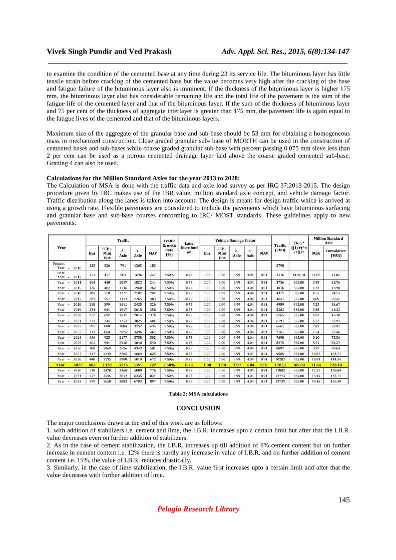
to examine the condition of the cemented base at any time during 23 its service life. The bituminous layer has little tensile strain before cracking of the cemented base but the value becomes very high after the cracking of the base and fatigue failure of the bituminous layer also is imminent. If the thickness of the bituminous layer is higher 175 mm, the bituminous layer also has considerable remaining life and the total life of the pavement is the sum of the fatigue life of the cemented layer and that of the bituminous layer. If the sum of the thickness of bituminous layer and 75 per cent of the thickness of aggregate interlayer is greater than 175 mm, the pavement life is again equal to the fatigue lives of the cemented and that of the bituminous layers. Maximum size of the aggregate of the granular base and sub-base should be 53 mm for obtaining a homogeneous mass in mechanized construction. Close graded granular sub- base of MORTH can be used in the construction of cemented bases and sub-bases while coarse graded granular sub-base with percent passing 0.075 mm sieve less than 2 per cent can be used as a porous cemented drainage layer laid above the coarse graded cemented sub-base. Grading 4 can also be used. Calculations for the Million Standard Axles for the year 2013 to 2028: The Calculation of MSA is done with the traffic data and axle load survey as per IRC 37:2013-2015. The design procedure given by IRC makes use of the IBR value, million standard axle concept, and vehicle damage factor. Traffic distribution along the lanes is taken into account. The design is meant for design traffic which is arrived at using a growth rate. Flexible pavements are considered to include the pavements which have bituminous surfacing and granular base and sub-base courses conforming to IRC/ MOST standards. These guidelines apply to new pavements.
Table 2: MSA calculations
CONCLUSION
The major conclusions drawn at the end of this work are as follows: 1. with addition of stabilizers i.e. cement and lime, the I.B.R. increases upto a certain limit but after that the I.B.R. value decreases even on further addition of stabilizers. 2. As in the case of cement stabilization, the I.B.R. increases up till addition of 8% cement content but on further increase in cement content i.e. 12% there is hardly any increase in value of I.B.R. and on further addition of cement content i.e. 15%, the value of I.B.R. reduces drastically. 3. Similarly, in the case of lime stabilization, the I.B.R. value first increases upto a certain limit and after that the value decreases with further addition of lime.
Vivek Singh Pundir and Ved Prakash Adv. Appl. Sci. Res., 2015, 6(8):134-147 _____________________________________________________________________________
146 Pelagia Research Library
In the field of stabilization of sub grades, there is a lot of scope for further work. Similar stabilizations can be done using various other different materials available, most important being RBI Grade 81. It is a very new patented material and has a large scope in research work. Stabilizations can be performed on different type of soils. The stabilization can also be done with different combinations of stabilizers like cement and lime mixed together. Acknowledgement Author would like to thank to Mr Ved Prakash (Department of Civil Engineering, Geeta Institute of Management & Technology, Panipat, Haryana) for supporting this work by providing a good research environment and related facilities.
REFERENCES
[1] IRC: 37- 2013-2015: Guidelines for the design of flexible pavements (Second Revision) Pradhan Mantri Gram Sadak Yojana (PMGSY) Soil Survey, National Rural Roads Development Agency. [2] Prasad D, G V R Prasada Raju, M Anjan Kumar, EJGE Vol. 13, Bund. D 2009 [3] Kolay, P.K. Sii, H.Y. and Taib, S.N.L. International Journal of Civil and Environmental Engineering 3:2 2011. [4] Joel H. Beeghly “Recent Experiences with Lime–Fly Ash Stabilization of Pavement Subgrade Soils, Base and Recycled Asphalt“2003 International Ash Utilization Symposium. Centre for Applied Energy Research University of Kentucky’ paper #46 [5] Aykut Senola,, Tuncer B.Edilb, Md.Sazzad Bin- Shafiquec, Hector A. Acostad ,Resources, Conservation and Recycling 46 ( 2006) 365-376. [6] Raju Sarkar, S.M. Abbas, J.T. Shahu, International Journal of Earth Sciences of Engineering ISSN 0974-5904, Volume 04. No.06 SPL, October 2011, pp 138-142. [7] IRC: SP: 72-2007 “Guidelines for the design of flexible pavements for low volume rural road”. [8] Basak, S., Bhattacharya, A. K and Paira, L. K., (2004),“Utilisation of Fly Ash in Rural Road Construction in India and its Cost Effectiveness”, Electronic Journal of GoetechEngineering. [9] Gaulkar, M. P., (1999), “Construction of Roads in BlackCotton Soil”, Indian Highways, New Delhi. Semmilink. C.J. and Visser, A. T., (1994), Journal of Transportation Engineering. Vol.120, Issue 4, pp 570- 589. [10] Mithra Dewars; Satender Kumar & Mohit Verma; (2009) “A Case Study On Rapid Pavement Construction by In-Situ Soil Stabilization” Legend Surface Developers Pvt. Ltd., New Delhi [11] IRC: SP: 20-2002 RecommendedDesign Criteria for rural road design. [12] Highway Material Testing, lab manual by S.K. Khanna and C.E.G. Justo [13] Tom V. Mathew, (2009), Entitled “Pavement materials: Soil Lecture notes in Transportation Systems Engineering” [14] Sahoo Biswajeet & Nayak Devadatta, (2009) “A Study of Subgrade Strength Related to moisture” [15] IRC-SP 72-2007, “Guidelines for the Design of Flexible Pavements for Low Volume Rural Roads” IRC, New Delhi. [16] S.P. Bindra “A Text Book of Highway Engineering” Dhanpat Rai Publications, New Delhi [17] Arman, A., and Munfakh, G.A. Stabilization of Organic Soils with Lime. Engineering Research Bulletin No. 103, Division of Engineering Research, Louisiana State University, Baton Rouge, 1970. [18] Alexander, M.L., Smith, R.E., and Sherman, G.B. Relative Stabilizing Effect of Various Limes on Clayey Soils. Bulletin 381, Highway Research Board, 1972. [19] Brown, J.J., Brandon, T.L., Daniels, W.L., DeFazio, T.L., Filz, G.M., and Mitchell, J.K. Rapid Stabilization/Polymerization of Wet Clay Soils: Phase I Literature Review. Air Force Research Laboratory, Tyndall AFB FL, 2004. [20] Carlsten, P., and Ekstrom, J. Lime and Lime/Cement Columns. Swedish Geotechnical Society Report 4:95E, Linköping, 1995. [21] Chou, L. Lime Stabilization: Reactions, Properties, Design, and Construction. State of the Art Report 5, Transportation Research Board, Washington, DC, 1987. [22] Eades, J.L, and Grim, R.E. Reaction of Hydrated Lime with Pure Clay Minerals in Soil Stabilization. Bulletin 262, Highway Research Board, Washington, DC, 1960. [23] Eades, J.L., and Grim, R.E. A Quick Test to Determine Lime Requirements for Soil Stabilization. Highway Research Record 139, Highway Research Board, Washington, DC, 1966. [24] Gow, A.J., Davidson, D.T., and Sheeler, J.B. Relative Effects of Chlorides, Lignosulfonates and Molasses on Properties of a Soil-Aggregate Mix. Bulletin 282, Highway Research Board, Washington, DC, 1960. [25] Ingles, O.G., and Metcalf, J.B. Soil Stabilization: Principles and Practice. Butterworths, Sydney, 1972.

Vivek Singh Pundir and Ved Prakash Adv. Appl. Sci. Res., 2015, 6(8):134-147 _____________________________________________________________________________
147 Pelagia Research Library
[26] Jacobson, J.R., Filz, G.M., and Mitchell, J.K., Factors Affecting Strength Gain in Lime-Cement Columns and Development of a Laboratory Testing Procedure, Report VTRC 03-CR16, Virginia Transportation Research Council, Charlottesville, VA, 2003. [27] Kunze, G.W. Pretreatment for Mineralogical Analysis. C.A. Black et al. ed., Methods of Soil Analysis, Part 1, Agronomy Monograph 9. American Society of Agronomy, Madison, WI, 1965. [28] Lees, G., Abdelkader, M.O., and Hamdani, S.K. (1982). Highway Engineer, Vol. 29, No. 12, 1982, pp. 2-8. [29] Little, D.N. Handbook for Stabilization of Pavement Subgrades and Base Courses with Lime. Kendall/Hunt, Iowa, 1995. [30] Miura, N., Horpibulsuk, S., and Nagaraj, T.S. Soils and Foundations, Japanese Geotechnical Society, Vol. 41, No. 5, 2002, pp. 33-45. [31] Rauch, A.F., Harmon, J.S., Katz, L.E., and Liljestrand, H.M. Liquid Soil Stabilizers: Measured Effects on Engineering Properties of Clay. In Transportation Research Record No. 1787. Transportation Research Board, Washington, DC, 2002. [32] Sinha, S.P., Davidson, D.T., and Hoover, J.M. Lignins as Stabilizing Agents for Northeastern Iowa Loess. Proceedings of the Iowa Academy of Science, 69th Session, Iowa, 1957. [33] Thompson, M.R., and Eades, J.L. Journal of the Soil Mechanics and Foundation Division, ASCE, Vol. 96, No. SM2, 1970. [34] Tingle, J.S, and Santoni, R.L. Stabilization of Clay Soils with Non traditional Additives. In Transportation Research Record 1819. Transportation Research Board, Washington, DC, 2003. [35] Yotam Engineering Ltd. RBI Grade 81: A Soil Stabilizer for Paving Technology. Yotam Engineering Ltd., Israel, 2004. [36] “Soil Stabilization and Pavement Recycling with Self- Cementing Coal Fly Ash.” American Coal Ash Association Education Foundation, Colorado (2008). [37] “State-of-the-Art Report on Soil Cement.” ACI 230.1R-90, ACI Materials Journal, Vol. 87, No. 4, (1990), pp. 23. [38] Little, D. and S. Nair, “Background for Development of Standard Practice for Modification and Stabilization of Subgrade Soils and base Courses.” NCHRP 20-07, (2008). [39] National Lime Association, “Technical Brief: Mixture Design and Testing Procedure for Lime Stabilized Soils.” Portland Cement Association, “Soil-Cement Laboratory Handbook.” Portland Cement Association, Illinois (1992). [40] Terrel, R. L., J. A. Epps, E. J. Barenberg, J.K. Mitchell, and M. R. Thompson, “ Soil Stabilization in pavement Structures - A User Manual.” FHWA Research Report No. FHWA-IP-80-2, WA (1979). [41] “Guidelines for Modification and Stabilization of Soils and Base for Use in Pavement Structures.” (March 2008). [42] United Facilities Criteria (3-250-11). “Soil Stabilization for Pavements, TM 5-822- 14/AFJMAN 32/1019.” (2004). [43] Barbu,B., Mcmanis, K. and Nataraj, M. (2004). “Study of silts moisture susceptibility using the tube suction test”, Transportation research board, annual meeting, CD-ROM publication, National research council, Washington D.C. [44] Bhattacharja, S., Bhatty, J.I. (2003) “Comparative performance of the Portland cement and lime stabilization of moderate to high plasticity soils”, Portland cement association. [45] Brooks, R., Udoeyo F.F., Keerthi V. Takkalapelli. (2011) American Society of Civil Engineers, Vol. 23, No. 5, pp. 711-716