Embed Size (px)
Citation preview

Seediscussions,stats,andauthorprofilesforthispublicationat:https://www.researchgate.net/publication/303524095
EffectofthermomechanicalprocessingscheduleonthetextureandmicrostructureofpipelinegradeAPIX80microalloyedsteel
ConferencePaper·February2016
CITATIONS
0
READS
132
5authors,including:
Someoftheauthorsofthispublicationarealsoworkingontheserelatedprojects:
StudyonEvolutionoflowtemperaturenanobainiticsteelViewproject
DevelopmentofQuenchandPartioningSteelthroughHotstripmillrouteViewproject
RajinikanthV
CouncilofScientificandIndustrialResearch(C…
24PUBLICATIONS277CITATIONS
SEEPROFILE
ParikshitMunda
IndianInstituteofTechnologyKanpur
8PUBLICATIONS28CITATIONS
SEEPROFILE
TipuKumar
NationalMetallurgicalLaboratory
3PUBLICATIONS2CITATIONS
SEEPROFILE
SandipGhoshChowdhury
NationalMetallurgicalLaboratory
90PUBLICATIONS958CITATIONS
SEEPROFILE
AllcontentfollowingthispagewasuploadedbyRajinikanthVon26May2016.
Theuserhasrequestedenhancementofthedownloadedfile.

Effect of thermomechanical processing schedule on the texture and
microstructure of pipeline grade API X80 microalloyed steel
V. Rajinikanth
1,*, P.Munda
1, Tipu Kumar
1, Sandip Ghosh Chowdhury
1, Sandeep Sangal
2
1CSIR-National Metallurgical Laboratory, Jamshedpur,834007,India
2Department of Materials Science Engineering, IIT Kanpur,208016,India
Email: [email protected]
ABSTRACT
The presence of micro alloying constituents like Ti, Nb in microalloyed steel enhances its mechanical
properties through grain size control and precipitation strengthening. The strengthening capability of
microalloying additions can be fully utilized by choosing proper thermomechanical processing (TMP)
schedule. The TMP schedule needs to be designed based on determination of critical temperatures of
transformation in steel including no recrystallisation temperature ( i.e ., Tnr ) of microalloyed steels. The
TMP was carried out on API X80 grade pipeline steel using Gleeble® 3800 Thermal mechanical
simulator. The samples were deformed in plain strain condition at three different temperatures (860, 950
and 1050°C) by keeping other deformation parameters constant. The deformation temperature was
chosen based on CCT and Tnr determination studies. The deformed samples were examined in EBSD and
TEM to obtain the texture and microstructural information. It is also observed that formation of acicular
ferrite and bainite microstructures in these steel is very much dependent on the deformation strain levels
in the austenite matrix prior to transformation. The grain boundary misorientation angle distribution
obtained from EBSD analysis can be a very important parameter to distinguish the different
microstructural constituents apart from grain shape and image quality.
KEYWORDS: pipeline steel, Gleeble, Tnr, EBSD, microtexture, acicular ferrite
INTRODUCTION
The presence of micro alloying constituents
like Ti, Nb in microalloyed steel enhances
its mechanical properties through grain size
control and precipitation strengthening1-4
.
The development of pipeline steel grades
with higher YS (X60 to X80 to X100)
depends on achieving the grain size
refinement by pancaking the austenite prior
to transformation to ferrite5,6
. The desired
transformation is partly diffusion less
leading to steel microstructure of acicular
ferrite and bainite. The role of niobium in
raising the no recrystallisation temperature
(i.e., Tnr) significantly is well known7,8
. The
strengthening capability of microalloying
additions can be fully utilized by choosing
proper thermomechanical processing (TMP)
schedule. The TMP schedule needs to be
designed based on determination of critical
temperatures of transformation in steel
including Tnr of microalloyed steels9,10
. The
determination of Tnr is mostly determined
by Mutihit deformation method. This paper
studies the effect of deformation at different
temperatures (i.e., below and above Tnr) on
evolution of texture and microstructure of
pipeline grade API X80 microalloyed steel.
MATERIAL & METHODS
The APIX80 grade microalloyed steel was
available in the form of rolled plates
supplied by M/s Arcelor Mittal, USA. The
chemical composition of the steel is 0.04C-
0.26Si-1.75Mn-0.009P-0.034Al-0.085Nb-
0.015Ti-0.0046N-0.8(Ni+Cu+Mo) in mass

%. The hot deformation by plain strain
compression was carried out in a Gleeble ®
3800 thermomechanical processing
simulator with Hydrawedge. The sample
sizes of 20 mm x15mm x10 mm rectangular
blocks were cut off from the alloy plates and
their surface were smooth finished to ensure
proper electrical contact for gleeble testing.
The tantalum foils were used between the
WC anvils and the sample to reduce friction
and protect the anvils. Tnr of the steel was
determined by carrying out multihit
deformation method. The CCT diagram was
generated using JMATPRO and performing
dilatometry in Gleeble to determine the
transformation temperatures. Based on the
above studies, the TMP was carried out at
860°C, 950°C and 1050°C after soaking at
1200°C for 500s up to strain of 0.8 at a
strain rate of 5s-1
. The samples were
immediately allowed to free cooling after
deformation. EBSD experiments on the
TMP samples was carried out on the
transverse section using a TSL OIM data
collection system attached to FEI-Nova
nanoSEM microscope. The microtexture
analysis was carried out using TSL-OIM
analysis software. For texture analysis care
has been taken to rotate the pole figure along
RD by 90° , as only TD section was
accessible in a gleeble plain strain
compression tested sample.
Fig.1: Schematic of plain strain compression
testing in Gleeble
RESULTS AND DISCUSSION
The Tnr of the experimental steel was
determined by multihit hot deformation in a
plain strain compression facility. The
samples were soaked at 1200°C for 10 min
followed by cooling to first deformation
temperature of 1150°C at a rate of 10°C/s
followed by soaking time of 5 sec prior to
deformation. The deformation was carried
out for 0.1 strain at a strain rate of 2s-1
followed by interpass time of 5s between
successive deformation passes.
The deformation was carried out at
temperature intervals of 25°C up to 900°C
followed by free cooling. The true stress-
strain curves of the multihit deformation is
shown in Fig.2. The analysis of the multihit
deformation data was carried out by several
researchers by examining the changes in
mean flow stress over the deformation
temperature range11-13
. The mean flow
stress was calculated by integrating the
stress strain curve over the strain range
using Origin. The Tnr of 1000°C was
determined for the steel based on the
deviation in the slope of mean flow stress
vs. temperature plot.
Fig.2: True stress-strain curves of multihit
deformation for Tnr determination

Fig.3: MFS Vs 1/T plot
The simulated transformation temperatures
of the experimental steel was found to be
828°C for austenite to ferrite transformation,
Ac3 ;598°C for Bainite transformation; and
427°C for martensite start Ms. The CCT
dilatometry in gleeble was carried out at
cooling rate of 20°C/s is shown in Fig.4.
The free cooling in the hot deformation tests
correspond to a cooling rate of 20°C/s. The
bainite transformation temperatures obtained
via gleeble CCT dilatometry correlate well
with the predicted transformation
temperatures obtained via JMATPRO. The
Bainite start temperature was ~613°C and
the transformation complete at 523°C .
From the studies, it is clear that bainite
forms from austenite on continuous cooling
at 20°C/s.(Fig.5)
Fig.4: CCT Diagram of experimental steel
Fig.5: CCT dilatometry of experimental steel at
20°C/s
Based on the above results, After soaking at
1200° C for 500s , three deformation
schedules up to 0.8 strain at a strain rate of
5s-1
was carried out at: (i) 50°C above Tnr-
1050°C ;(ii) 50°C below Tnr - 950°C and
(iii) well below Tnr and ~just above Ac3
temperature- 860°C. The deformations was
carried out to understand the effectiveness of
Tnr on the development of texture and
microstructure of the steel under
investigation.
0.0 -0.2 -0.4 -0.6 -0.8 -1.0
0
-50
-100
-150
-200
-250
-300
-350
Tru
e S
tre
ss
,MP
a
True Strain
860
950
1050
Fig.6: Flow curves at different deformation
temperatures.
The samples after deformation were
sectioned along TD plane and samples were
prepared for optical metallography and
EBSD. PAG etching was performed on the
samples to estimate the austenite grain size
and shape prior to transformation to
bainite/acicular ferrite microstructures14
.
The etchant composition was 1.35 gms of
picric acid in 100ml distilled water and
mixed with 0.5ml of sodium alkylsulfonate
(Extran) and 1ml HCl. The pancaking of
austenite grains will be clearly evident from
the PAG micrographs. The average grain
size was measured using ImageJ, public
domain image processing software.
Fig.7a shows that austenite grain sizes after
deformation at 1050°C shows large
equiaxed recrystallized grains ~24µm taken
from the centre of deformed region. There is

no sign of pancaking due to dynamic
recrystallization. Fig.7b shows pancaking of
austenite with decreasing grain size ~7µm,
with the deformation band widths ~25 µm
containing mixed microstructure at 950°C.
Fig.7c shows complete pancaking with very
fine austenite sizes~2µm and smaller width
of deformation bands~10 µm for 860°C
sample.
(a)
(b)
(c)
Fig.7: PAG micrographs for samples deformed
at (a) 1050°C; (b)950°C; (c) 860°C
(a)
(b)
(c)
Fig.8: IPF maps for samples deformed at (a)
1050°C; (b)950°C; (c) 860°C
EBSD Maps were acquired at 500X with
average confidence index > 0.6 with a step
size of <0.15µm. Fig.8 shows the inverse
pole figure maps along with high angle grain
boundaries clearly shows the grain size
variation obtained after reduction up to 0.8
true strain at three different temperatures.
The presence of pancaked elongated grains
is very clear from the 860°C TMP sample
with most grains oriented with <111> plane
normal to the rolling section.
(a)
(b)
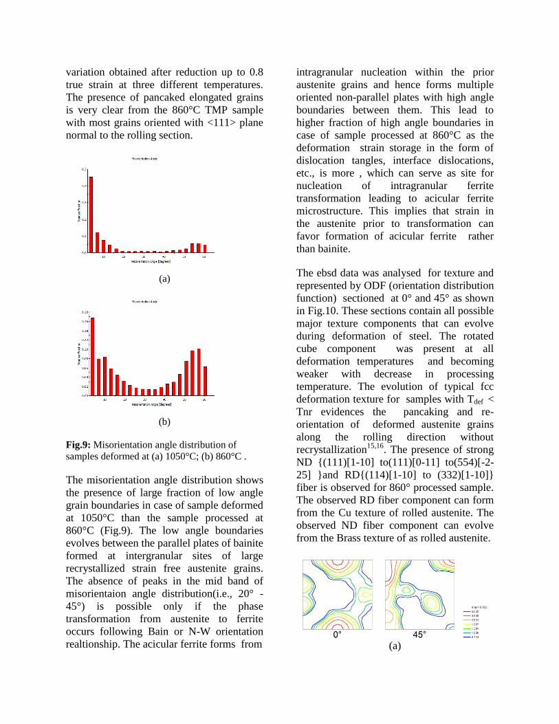
Fig.9: Misorientation angle distribution of
samples deformed at (a) 1050°C; (b) 860°C .
The misorientation angle distribution shows
the presence of large fraction of low angle
grain boundaries in case of sample deformed
at 1050°C than the sample processed at
860°C (Fig.9). The low angle boundaries
evolves between the parallel plates of bainite
formed at intergranular sites of large
recrystallized strain free austenite grains.
The absence of peaks in the mid band of
misorientaion angle distribution(i.e., 20° -
45°) is possible only if the phase
transformation from austenite to ferrite
occurs following Bain or N-W orientation
realtionship. The acicular ferrite forms from
intragranular nucleation within the prior
austenite grains and hence forms multiple
oriented non-parallel plates with high angle
boundaries between them. This lead to
higher fraction of high angle boundaries in
case of sample processed at 860°C as the
deformation strain storage in the form of
dislocation tangles, interface dislocations,
etc., is more , which can serve as site for
nucleation of intragranular ferrite
transformation leading to acicular ferrite
microstructure. This implies that strain in
the austenite prior to transformation can
favor formation of acicular ferrite rather
than bainite.
The ebsd data was analysed for texture and
represented by ODF (orientation distribution
function) sectioned at 0° and 45° as shown
in Fig.10. These sections contain all possible
major texture components that can evolve
during deformation of steel. The rotated
cube component was present at all
deformation temperatures and becoming
weaker with decrease in processing
temperature. The evolution of typical fcc
deformation texture for samples with Tdef <
Tnr evidences the pancaking and re-
orientation of deformed austenite grains
along the rolling direction without
recrystallization15,16
. The presence of strong
ND {(111)[1-10] to(111)[0-11] to(554)[-2-
25] }and RD{(114)[1-10] to (332)[1-10]}
fiber is observed for 860° processed sample.
The observed RD fiber component can form
from the Cu texture of rolled austenite. The
observed ND fiber component can evolve
from the Brass texture of as rolled austenite.
(a)

(b)
(c)
(d)
Fig.10: ODF sections at ᵠ2 =0°;45° for samples
deformed at (a) 1050°C; (b)950°C; (c) 860°C;
(d) at ᵠ2 =45° section with important texture
components in Bunge notation17
.
The TEM examination of the sample
deformed at 860°C shows bainite plates with
heavy dislocation structure (Fig.11a). The
dark field imaging at a higher magnification
shows the presence of very fine niobium
carbide precipitates(Fig.11b) at the
dislocation sites. The niobium carbide
precipitation was responsible for the solute
drag effect and hence raise the Tnr of the
given steel providing a large deformation
window that can pancake the austenite at
lower rolling loads and thus favors
formation of high strength acicular ferrite
and bainite microstructures.
(a)
(b)
Fig.11: TEM micrographs of sample deformed
at 860°C showing bainitic ferrite plates and
Niobium carbide precipitates under dark field.
Conclusion
The given microalloyed steel of APIX80
grade was deformed in plain strain
condition at three different temperatures
(860, 950 and 1050°C) by keeping other
deformation parameters constant. The Tnr of
the steel was determined by mean flow
stress method and found to be ~1000°C. The
CCT dilatometry at 20°C also shows that it
favors bainite transformation at ~600°C as
predicted by JMATPRO. The EBSD
examination of samples deformed below Tnr
showed pancaking of austenite leading to
fine grain sizes and large equiaxed grains
with bainitic ferrite plates for sample
deformed above Tnr. It is also observed that

formation of acicular ferrite and bainite
microstructures in these steel is very much
dependent on the deformation strain levels
in the austenite matrix prior to
transformation.
Acknowledgement
Thanks to Director, CSIR-NML for his
permission to publish this work. We thank
Amar K De, Arcelor Mittal USA,Global
R&D, Chicago, USA for providing the
microalloyed steel plates. The authors also
thank IPSG, CSIR-NML for funding the
research work under grant OLP-0214.
References
[1] Bing Feng, PhD Thesis, Department of
Materials Engineering, University of
Wollongong, 1991.
[2] P. Rodrigues et al., 6th Brazilian
Conference on Manufacturing Engineering,
Caxias Dus SUL, Brazil,2011.
[3] Linda Backe, PhD Thesis, Division of
Mechanical Metallurgy, Royal Institute of
Technology, Sweden, 2009.
[4] R.D.K. Misra, G.C. Weatherly, J.E.
Hartmann and A.J. Boucek, Mater.
Sci.Tech,Vo. 17, 2001,p.1119
[5] H.G. Hillenbrand etal., Niobium 2001,
Orlanda,Florida,USA,2001.
www.europipe.com/files/ep_tp_43_01en.pdf
[6] D. B. Rosado etal., Sustainable
construction and design 2013,
ojs.ugent.be/SCAD/article/download/742/73
0.
[7] G.J.Baczynski, J.J.Jonas and L.E.Collins,
Metall. and Mater.Trans. A, Vol. 30A,1999,
p. 3045.
[8] Y. He, S. Godet, P. J. Jacques and J. J.
Jonas, Metall. and Mater.Trans. A, Vol.
37A, 2006, p. 2641.
[9] M.I. Vega, ISIJ Inter., Vol. 39, No.12,
1999,p.1304.
[10] L.P. Karjalainen, T. M. Maccagno and
J. J. Jonas, ISIJ Inter., Vol. 35, No.12,
1995,p.1523.
[11] J. J.Jonas, C. Ghosh, X. Quelennec, V.
V.Vasabe, Int. conference on
Thermomechanical Simulation and
Processing of Steel, SIMPRO, RDCIS,
SAIL, Ranchi, 2012, p.1-10
[12] J. J. Jonas, ISIJ Inter., Vol. 40, No.8,
2000,p.731.
[13] L.N. Pussegoda and J.J. Jonas, ISIJ
Inter., Vol. 31, No.3, 1991,p.278.
[14] C. Garcia de Andres et al.,
Mater.Charact. Vol.46, No.5,2001,p.389.
[15] R.K. Ray and J. J. Jonas,
Inter.Mater.Rev., Vol.35, No.1, 1990,p.1.
[16] L. Kestens and J. J. Jonas, ASM
Handbook, Vol.14A, Metal working: Bulk
Forming, ASM, 2005, p. 685-698
[17] K.A. Annan, M.Sc Thesis, MSME
Dept, Univ. of Pretoria, SA, 2012
View publication statsView publication stats