Embed Size (px)
Citation preview
Effect of tungsten carbides properties of overlay welded WC/NiSiB composite coatings
Rickard Seger
MG 202X Examensarbete inom Maskinteknik
Handledare: Lorenzo Daghini
Höganäs, Sverige 2013

Abstract
To get a long life of a product which is subjected to heavy mechanical wear, materials with particularly good properties such as high hardness and the ability to resist high temperature is required. Tungsten carbide is a material which has these properties, but to manufacture large products for mining industry or agriculture entirely of this material is neither practical nor quite beneficial when the disadvantages of the materials such as brittleness, high weight and high price will have a major affect. To exploit material properties in a beneficial way it is more convenient to coat the surface on ordinary steel with a composite coating consisting of tungsten carbides in a nickel base matrix. By this way it is possible to utilize the steels ductility, lower weight and lower price along with the tungsten carbides superior abrasion resistance. The method for coating the steel surfaces of this composite material is usually some welding process. Laser or plasma welding with filler material in powder form is often used as a beneficial method for this.
Höganäs AB is a manufacturer of metal powder and conducts development of metal powder mixtures for surface coating purposes. This report is a study of various types of tungsten carbide powder used for the surface coating process “Laser Cladding”. As tungsten carbide powders are available in various shapes and compositions, the goal is to find out what the different tungsten carbide types characteristics, advantages and disadvantages are when used in surface coatings, and also how they behave in the welding process. For this, the different types of powders were analyzed with respect to their properties in the unwelded condition. Thereafter samples of surface coatings were welded with the different types of tungsten carbides and their coating properties were analyzed. This has been done by measuring the dilution with X-ray diffraction, metallographic studies in both the light optical and scanning electron microscopy and hardness measurements. Finally, the coatings are subjected to abrasion test according to ASTM G65-4 for abrasive wear.
The different types of tungsten carbides covered in this report are:
1. Spherical Cast Carbide 2. Fused and crushed tungsten carbide, FTC 3. Mono Cristalline tungsten carbide 4. PA2, WC-Co carbide 5. Agglomerated WC-Co carbide
It appeared early in welding attempts that the carbide type PA2 (WC-Co) could not be weld with appropriate results, so further experiments of this type were canceled.
After analysis of the welded coatings it can be concluded that Spherical Cast Carbide has the best wear resistance closely followed by Fused and crushed tungsten carbide and Mono Cristalline tungsten carbide. Agglomerated WC-Co carbide showed poor abrasion resistance in overlap areas, but in between these the result has appropriate properties were also a low surface roughness is achieved compared to the other materials. This could provide opportunities for new applications for this type of carbide where good surface finish is required, if it is possible to eliminate the problems in overlap areas.

Sammanfattning
För att få ut lång livslängd på en produkt som utsätts för tungt mekaniskt slitage krävs material med särskilt bra egenskaper som till exempel hög hårdhet och klara av höga temperaturer. Volframkarbid är ett material som har dessa egenskaper, men att tillverka en stor produkt för gruvindustri eller jordbruk helt i detta material är varken praktiskt möjligt eller helt fördelaktigt då man även får med sig vissa nackdelar med materialet som sprödhet, hög vikt och att det är mycket dyrt. För att utnyttja materialens egenskaper på ett fördelaktigt sätt belägger man istället ytan på vanligt stål med en kompositbeläggning bestående av volframkarbider i en nickelbasmatris. Detta gör att man utnyttjar stålets seghet, lägre vikt och lägre pris tillsammans med volframkarbidernas överlägsna nötningsmotstånd. Metoden för att belägga stålytor med detta kompositmaterial är oftast någon svetsprocess. Laser eller plasmasvetsning med tillsatsmaterial i form av pulver är ofta en fördelaktig metod för detta.
Höganäs Ab är en tillverkare av metallpulver och bedriver utveckling av metallpulverblandningar för ytpåsvetsning. Denna rapport är en studie av olika typer av volframkarbidpulver som används för laserytpåsvetsning. Då volframkarbidpulver finns i olika former och sammansättningar är målet att ta reda på vilka de olika typernas egenskaper, för och nackdelar är när de används i ytbeläggningar, och även hur de beter sig i svetsprocessen. För detta har de olika typerna av pulver analyserats med avseende på deras egenskaper i osvetsat tillstånd. Därefter har svetsprover utförts med olika de olika volframkarbidtyperna och ytbeläggningarnas egenskaper har analyserats. Detta har skett med uppsmältningsmätningar med röntgendiffraktion, metallografiska undersökningar i både ljusoptiskt- och svepelektronmikroskop och hårdhetsmätningar. Avslutningsvis har beläggningarna utsatts för nötningsprov enligt standarden ASTM G65-4 för abrasiv nötning.
De olika volframkarbidtyperna som behandlas i denna rapport är:
1. Spherical Cast Carbide 2. Fused and crushed tungsten carbide, FTC 3. Monocristalline tungsten carbide 4. PA2, WC-Co carbide 5. Agglomerated WC-Co carbide
Det visade sig tidigt vid svetsförsöken att typen PA2 (WC-Co) inte gick att svetsa med fullgott resultat, så vidare försök på denna typ avbröts. Efter analyser av de svetsade ytbeläggningarna kan det konstateras att Spherical Cast Carbide har bäst nötningsmotstånd tätt följd av Fused and crushed tungsten carbide och Monocristalline tungsten carbide. Agglomerated WC-Co carbide visade på dåligt nötningsmotstånd i de områden där svetssträngarna överlappar varandra men mitt i strängarna finner man ett gott resultat där man dessutom får en god ytfinhet jämfört med de andra materialen. Detta kan ge möjlighet till nya användningsområden där god ytfinhet krävs för denna typ, om man kan eliminera problemen i överlappsområdena.

Contents 1. Introduction ........................................................................................................................................................ 1
1.1 Background ................................................................................................................................................... 1
1.2 Purpose ......................................................................................................................................................... 1
1.3 Problem description ...................................................................................................................................... 2
1.4 Limitations ..................................................................................................................................................... 2
2. Literature survey ................................................................................................................................................. 3
2.1 Tungsten Carbide .......................................................................................................................................... 3
2.2 Laser cladding process .................................................................................................................................. 3
2.3 Other overlay welding methods ................................................................................................................... 5
2.4 Laser cladding of WC/Ni coatings ................................................................................................................. 6
2.5 Coating Defects ............................................................................................................................................. 6
2.6 Abrasive wear ............................................................................................................................................... 6
3. Method................................................................................................................................................................ 7
3.1 Materials ....................................................................................................................................................... 7
3.1.1 Carbides ................................................................................................................................................. 7
3.1.2 Matrix ..................................................................................................................................................... 8
3.1.3 Substrate ................................................................................................................................................ 8
3.2 Process .......................................................................................................................................................... 9
3.3 Analysis methods ........................................................................................................................................ 11
3.3.1 Powder properties ............................................................................................................................... 11
3.3.2 Coating properties ............................................................................................................................... 11
4. Results ............................................................................................................................................................... 14
4.1 Carbides ...................................................................................................................................................... 14
4.1.1 Size distribution ................................................................................................................................... 14
4.1.2 Hardness .............................................................................................................................................. 14
4.1.3 Carbon content and density ................................................................................................................ 15
4.1.5 Metallography ...................................................................................................................................... 16
4.2 Matrix powder ............................................................................................................................................ 19
4.2.1 Carbon content and density ................................................................................................................ 19
4.2.2 Melt interval ......................................................................................................................................... 19
4.2.3 Metallography ...................................................................................................................................... 20
4.4 Process ........................................................................................................................................................ 21
4.3 Coatings ....................................................................................................................................................... 22
4.3.1 Dilution ................................................................................................................................................. 22

4.3.2 Cracks ................................................................................................................................................... 22
4.3.3Hardness measurements ...................................................................................................................... 23
4.3.4 Metallography ...................................................................................................................................... 25
4.3.5 Area fractions ....................................................................................................................................... 37
4.3.6 Changing process parameters ............................................................................................................. 39
4. 5 Wear ........................................................................................................................................................... 41
4.5.1 Wear test results .................................................................................................................................. 41
4.5.2 Metallography wear tests .................................................................................................................... 42
5. Discussion .......................................................................................................................................................... 46
6. Conclusions ....................................................................................................................................................... 49
7. Future work ....................................................................................................................................................... 50
References ............................................................................................................................................................ 51
Appendix 1: W-C phase diagram........................................................................................................................... 52
Appendix 2 - Size distribution of carbide powders ............................................................................................... 53
Appendix 3 –PA2 Metallographic evaluation ....................................................................................................... 55
Appendix 4 - Preheating ....................................................................................................................................... 57
Appendix 5 – Wear ................................................................................................................................................ 58
Appendix 6 - Additional pictures of wear test samples ........................................................................................ 59

1
1. Introduction
1.1 Background High wear resistance is required in many industrial applications to extend the life of parts during production. A cost effective solution is to coat the surface of an exposed region with a material having superior wear resistance. The choice of the surfacing method and coating material depends on the application demands. Coating by overlay welding provides good bond strength between the coating and the substrate, relatively thick and pore free deposits.
Welding methods such as Plasma Transferred Arc and laser cladding with additive metal powder mixes consisting of a nickel based matrix, NiSiB and tungsten carbides are commercially used in applications requiring high resistance to abrasive wear. The metal matrix works as a binder providing toughness while the tungsten carbides provide wear resistance. The wear resistance of a coating is affected by the amount, size, chemistry/ microstructure, morphology and degradation degree of the tungsten carbides as well as by the metal matrix selected.
Applications of tungsten carbide metal matrix composites are found in the mining industry to coat different drilling and digging parts, in agriculture for coating on plough shares, tillage equipment and cutters. In steel industry is tungsten carbide coatings used on for example guide rollers. Oil industry also uses this type of coatings in high wear applications. [1] Examples of applications are seen in figure 1.
Höganäs AB manufactures nickel based matrix powder. This powder is mixed with tungsten carbide powder sourced from external suppliers to form a powder mix ready to use for surface coating applications, this ready powder mix is the product Höganäs AB sell. Currently a number of different types of tungsten carbide powder are in use at Höganäs, but it is not so well known how the different types of tungsten carbides affect the behavior of the laser welding process and coating they are used for.
Figure 1: Coated plough share, digging equipment and a scraper.
1.2 Purpose Purpose with this project is to map the influence of tungsten carbide chemistry, amount, morphology and degree of degradation during welding on microstructure and wear resistance of overlay welded NiSiB/WC coatings for different types of tungsten carbides.
2
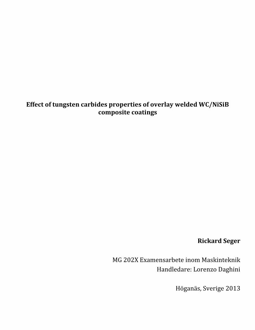
1.3 Problem description The problems in this project are to map:
Influence of carbide amount on wear properties is studied for: 40- 50- 60% Spherical cast carbides + NiSiB matrix
Influence of morphology and chemistry/microstructure on dissolution and wear properties: 50% Carbides + NiSiB matrix
Influence of Cr in matrix: 50% Carbides + NiCrSiB matrix
1.4 Limitations This project will only study laser cladding as process to limit the amount of work.
Five types of tungsten carbides are used, as these five are the most commonly used at Höganäs AB:
Spherical cast carbide
Fused and crushed tungsten carbide, FTC
Monocristalline tungsten carbide
PA2, WC-Co carbide
Agglomerated WC-Co carbide
Only one particle size of carbides is used; 53-150µm. For PA2 and agglomerated WC-Co carbide closest possible size is used as they are not provided in 53-150µm.
Matrix powder selected are NiSiB (1559-40) and NiCrSiB (1540-00) in same size (53-150µm) as the carbides.
Abrasive wear tests are done according to the ASTM G65-4 standard. Only 1559-40 + carbides is wear tested due to time limits of the project.

3
2. Literature survey
2.1 Tungsten Carbide Tungsten is a metal element with exceptional mechanical and thermal properties; it has the highest melt temperature of all metallic elements. In combination with carbon it forms tungsten carbide which counts as an refractory carbide, defined by a melting point over 1800°C, very high hardness and a good chemical resistance. Tungsten carbide can exist in two phases; WC and W2C, and have a hardness of 2000 – 2700 HV. Tungsten carbide powders come as monocristalline WC with a carbon content ≈ 6, 1% or eutectic WC/W2C with a carbon content ≈4% as seen in a carbon – tungsten phase diagram [Appendix 1]. Nominal properties of tungsten and tungsten carbides are presented in table 1. [2]
Table 1: Tungsten and tungsten carbide properties
Type: Melting Point Density
W 3410°C 19,3 [g/cm3]
WC 2870°C 17,2 [g/cm3]
W2C 2730°C 15,8 [g/cm3]
Common use for tungsten carbide besides surface coating applications are as cemented carbide in hard metal tools. The tungsten carbides is in this case sintered with a metallic binder, often cobalt and less often nickel, as good wettability is provided with these elements. To cut and grind tungsten carbide a tool of a harder material is needed, for example CBN (Cubic Boron Nitride) or diamond cutting- and grinding discs. [3]
2.2 Laser cladding process Laser processes have an industrial use for cutting and welding of a wide range of materials, nearly all weld able materials can be laser welded. LASER is an acronym for” Light Amplification by Stimulated Emission of Radiation” and is a light source producing a parallel beam of a specified wave length of light depending on which type of laser source are used. The beam is concentrated by a lens or mirrors to a focal point with a high energy density; material is immediately melted by the energy here. When welding with laser a shielding gas, often argon, is supplied to protect the molten material from contact with the surrounding air and to protect the lens from splashes and vapor from the melt. The high and concentrated energy makes it possible to deposit exact amounts of energy in well-defined spaces. Laser welding is mainly used for high precision welding in complicated details and materials to avoid high heat inputs or keep the thermal expansion as low as possible. [4]
There are several different types of Laser sources, the most common used for welding applications are [4]:
CO2 laser: The CO2 laser beam has a wave length of 10, 6 µm and have a very high power, mirrors are used for deflection and focusing of the beam. The CO2 laser wave length is more easily reflected than other laser types, this can cause problems on reflecting materials such as aluminum.
Nd: YAG-laser: The Nd: YAG-laser beam have a wave length of 1, 06µm and cannot come up to the high power output the CO2 laser produces. This laser beam can be led through optical fibers.
Fiber-laser: Fiber-laser have a wave length of 1, 07µm, a good beam quality is significant for this type and results in a high efficiency.
Diode-laser: Diode lasers have a short wave length of around 800-900 nm, beam quality has been a problem, but in recent years it has become better. This type are well suited for overlay welding where a wider beam is useful as it’s hard to get it concentrated enough for keyhole welding.
When laser is used for overlay welding the process is referred as Laser Cladding.
4
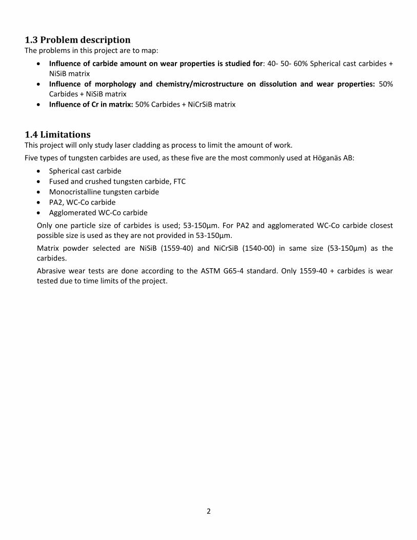
Advantages of laser cladding technology are a low degree of dilution of the substrate, a fine grain structure with high hardness due to the intense heat input and quick cooling. Overlay welding requires additive material to form a coating on the surface; the additives can be in the form of wire feed into the melt, preplaced powder on the surface or powder feed into the laser beam from a powder feeding device by a carrier gas. Laser cladding deposition rates can come up to 8 kg/hour and surface thickness from 0, 5 to 4 mm. [1]
Figure 2: Laser Cladding principle [1]
The principle of laser cladding with metal powder as consumable is a laser beam with powder supplied by a carrier gas coaxially or laterally into the beam and melt pool. A shielding gas is protecting the melt from contact with the surrounding air. [1]
Major process parameters for laser cladding with powder as additive material are: [5]
Laser power
Laser beam focus point
Laser beam spot size
Scanning speed
Powder characteristics (particle size, thermal properties etc.)
Powder feeding rate
Track overlap ratio
Gas flow rate
Preheating of substrate
Changing the parameters will affect the results in certain ways, this are studied in a number of articles. The article “Analysis of coaxial laser cladding process” describes the process parameter influences for certain results. About dilution of the substrate it is shown that the depth of the substrate melting zone increases linearly with laser power and that it is inversely proportional to the square root of scanning speed. The thickness of the clad layer depends mainly on the powder feeding rate and on the scanning speed. The laser power does not play an important role. [5] These theories are also confirmed in [6].

5
2.3 Other overlay welding methods Other welding methods used for hard coating applications are:
Plasma transferred arc – PTA.
A high density plasma arc is formed between a non-consumable electrode and the work piece, coating powder is injected into the arc to melt and form the coating. PTA has a higher productivity than laser with a deposition rate of up to 12 kg/hour and a deposition thickness of 1-6mm but not as controllable heat input as the laser process. [1]
Figure 3: Principle of PTA welding
MIG (Metal Inert Gas)
Metal Inert Gas welding can be used for overlay welding; additives for hard coatings such as carbides can be supplied in a tubular wire or be injected to the melt pool from the side. MIG has a relative high deposition rate of up to 10 kg/hour but gives a high dilution of between 15% and 25%; therefore several layers can be required to achieve acceptable surface properties. [1]
TIG (Tungsten Inert Gas)
Tungsten Inert Gas uses additive material in form of a rod or wire and can produce coatings with a thickness of up to 2 mm and a dilution from 10% and higher. Deposition rate is low, with a maximum around 2-3 kg/hour. Advantages of TIG are that it can weld a wide range of materials in high precision whithout slags, splatter or fumes. [1]
SAW (Submerged arc weld)
Submerged arc welding is a welding method with a very high deposition rate, up to 20 kg/hour and above can be possible to reach. Additive material used is wire or strip electrodes. The arc is formed between the electrode and base material under a powder bed which forms a protective slag in the process. Addition of metal powder or wire into the weld is possible. SAW is limited to be used on big flat surfaces. High heat input and high dilution is connected to this method. [1]
Powder welding
Powder welding is a manual welding method using an oxy-acetylene torch with powder fed into the flame. Thin layers, from 1, 5 to 5 mm can be deposited with a low deposition rate of 1-2 kg/hour and a high heat input, but low dilution. [1]
MMA (Manual Metal Arc)
Manual Metal Arc welding is mainly used for surface repairs of heavy equipment, advantage are it’s possible to weld outdoors. [4]

6
2.4 Laser cladding of WC/Ni coatings Dissolution of WC particles in Laser cladding are considered strongly dependent on the level of heat input, and an increased heat input leads to reduction of WC volume fractions in coatings. [7] Particle size also affects the WC particle dissolution, the dissolution is more pronounced for the smaller particles [8].
The shape of particles will also affect the carbide dissolution, when spherical and non-spherical particles are compared the use of non-spherical particles leads to higher particle temperature after their contact with laser radiation in the beam. [10]
In “Abrasive wear performance and microstructure of laser clad WC/Ni layers” are laser cladded coatings of monocristalline WC and eutectic WC/W2C carbides in Ni matrix studied and compared on wear and microstructure. It’s shown here that monocristalline WC carbides are less prone to dissolve in the matrix and due to this forms coatings with a higher volume fraction of WC carbides, this results in a better resistance to abrasive wear for the monocristalline coatings. [9] Regarding abrasive wear it is considered the wear resistance increases with a higher carbide concentration [8].
The effect of carbide degradation under abrasive conditions is studied in “Effect of carbide degradation in a Ni-
based hardfacing under abrasive and combined impact/abrasive conditions” where are high wear resistance is observed at low level carbide degradation, and it’s concluded the specific wear energy strongly depends on the content of primary hard phases. [12]
The difference in powder density between WC and Ni-based alloy can result in WC carbides sinking to the bottom of the melt pool, as the lower melting points and slower solidification rates of the Ni powder give time for the WC particles to sink. [11] Preheating plays an important role for avoiding cracks, cracks is described as mainly propagate perpendicular to the substrate surface, and does not affect the metallurgical bonding between substrate and coating. [7]
2.5 Coating Defects Defects occurring in metal matrix composite coatings are: cracks, porosity, bad bonding to substrate and uneven carbide distribution. Cracks are generally caused by overheating, to rapid cooling rate or differences in thermal expansions between the substrate and coating material. To minimize the risk of cracking preheated substrates and a low cooling rate are recommended. A low cooling rate is reached by bedding the laser cladded sample in the insulation material vermiculite or after heating. Porosity can depend on bad gas protection from the surrounding air, impurities on the substrate or in the additive material. Low dilution and bad bonding to the substrate can depend on problems with the powder feeding, low laser power or to high scanning speed. [1]
2.6 Abrasive wear Abrasive wear is loss of material on a surface as result of cutting, ploughing, grinding, and scratching in the contact area between two surfaces sliding along each other under load. Abrasive wear can be divided into two modes; two-body and three-body abrasive wear. Two body abrasion wear refers to hard rough surface which plows in a softer counter surface, three body abrasion refers to hard particles between the two sliding surfaces which are ploughing in at least one of the surfaces. [13]
Standardization of wear testing is done by ASTM International, and ASTM G65-4 is a test standard for abrasive wear. Wear is measured as volume loss in cubic millimeters for the particular test procedure specified. [14]

7
3. Method Here follows a description of the materials used in this project, process descriptions and the analysis methods used to evaluate the results.
3.1 Materials
3.1.1 Carbides Five different types of carbide powders are used; they are presented with their nominal properties in table 1. [15] Powders PA2 and agglomerated WC-Co are not supplied in size 53-150µm, closest possible size are therefore used.
Table 2: Nominal properties of carbide powders
Carbide powder C % Co % W% Particle size: type:
FTC (4570) 4 - Bal. 53-150µm WC/W2C
Monocristalline (4580)
6,1 - Bal. 53-150µm WC
Spherical cast (4590)
4 - Bal. 53-150µm WC/W2C
PA2 5,7 7,5 Bal. 45-106µm WC-Co
Agglomerated WC-Co (44712-10)
5,5 12 Bal. 53-106µm Agglomerated WC-Co
Spherical cast carbide (4590) Cast carbides which are spheriodized by a plasma torch to get the spherical shape. It has eutectic composition of WC/W2C. The meaning of “cast” in the product name of this carbide is the same as fused. [2]
FTC (4570) Fused Tungsten Carbides are irregular shaped carbides also consisting of a eutectic composition of WC/W2C, The FTC carbides are made by melting in arc furnace followed by cooling and crushing. Hardness is specified to
1900 – 2200 HV0.1. [16]
Monocristalline (4580) Monocristalline tungsten carbides consist only of WC and have a carbon content of 6, 1%, which is higher than the eutectic carbides. The monocristalline structure is more stable thermodynamically which results in a higher melting point. This carbide has lower density than WC/W2C carbides due to the existence of molecules consisting of only one W atom and one C atom. Hardness is specified to 2000 – 2200 HV0.1. [16]
PA2 PA2 is a cemented WC-Co powder made from recycled hard metal tools etc. The powder is crushed sintered products which consist of a cobalt matrix with WC carbides in size 1 µm roughly [15]. Cobalt starts melting at 1495°C, which is much lower than the tungsten carbides which have a melt temperature of 2870°C for the monocristalline WC. Further due the smaller size of the carbides they are more prone to dissolution in melt. PA2 has probably as a recycled material more impurities that will form gas during laser cladding and result in porosity. Previous experiences have shown bad results when welded.

8
Agglomerated WC-Co powder (44712-10) This powder also consists of roughly 1 µm WC carbides in a matrix of cobalt; the powder is made by spray drying of a suspension consisting of the metal powders WC carbides and a binder followed by a sintering process where the binder is burned out. Agglomerated WC-Co powder is not normally used for laser cladding or PTA application at the moment, the high heat input leads to dissolution of the carbides, gas formation and porosity in coatings, but with the lasers more controllable heat input and faster cooling rate it´s maybe possible to obtain a coating with acceptable properties. [15]
3.1.2 Matrix Two different matrix powders are used: 1559-40 a NiSiB powder, and 1540-00 a NiCrSiB Powder. These are the matrix powders Höganäs AB use for laser cladding of WC/Ni metal matrix coatings. Nominal chemistry of the powder, sieve cut and hardness Rockwell, HRC, are shown in table 3. Hardness reported gives an indication of the matrix hardness as it measured on coatings deposited by PTA; the hardness is generally higher for laser cladded coatings. [15]
Table 3: Nominal properties of matrix powders
Matrix powder
C % Ni % Si % B % Fe % Cr % Particle size: Coating hardness HRC
type:
1559-40 ≤0,06 Bal. 3 2,9 0,2 - 53-150µm 49* NiSiB
1540-00 0,25 Bal. 3,5 1,6 2,5 7,5 53-150 µm 40* NiCrSiB
3.1.3 Substrate Substrate used for the laser cladding tests are low alloy carbon steel SS-EN S 235 JR, specifications in table 4 [17]. For dilution calculations the iron content in the substrate is estimated to 99%. Two sizes of substrate are used: one small 100 x 70 x 10 mm for test welds and metallography samples; one big 210 x 60 x 20 mm for wear test samples. The big type for wear tests is after cladding cut into three small samples in size according to the ASTM G65-04 abrasive wear test specifications.
Table 4: SS-EN S235 JR
SS-EN S 235 JR C % Si % Mn % (max) S % (max) P % (max) Rel [MPa] Rm [MPa]
Contents: 0,12 0,25 0,7 0,035 0,035 210 360

9
3.2 Process
For the process will following problems be surveyed:
Map the influences on the main process parameters: laser power, speed and powder feeding on resulting coating properties.
Is it possible to obtain coatings with similar properties at different process settings (higher speed)?
For laser cladding a direct diode laser with maximum output power of 4 kW is used. The process is automatized with the laser mounted on a 5-axis industrial robot. Laser spot size is 12 x 1mm. Powder feeding nozzles are placed lateral in front of and behind the beam, but only powder feeding from the nozzle in front of the beam is used during this experiments. In figure 4 Höganäs Laser and powder feeding equipment are shown.
Figure 4: Höganäs direct diode laser
To determine the laser cladding parameters, these requirements on the resulting coating properties need to be fulfilled:
Coating properties
Dilution: < 10%
No porosity
No cracks
Thickness: > 0, 5 mm
Even carbide distribution The main parameters to adjust are:
Laser power [kW]
Speed [mm/s]
Powder feeding [g/min]
Overlap [mm]
Powder feeding flow is measured as [g/minute]. As different powders have different densities powder feeding is just set as a number on the machine; for this setting the feeding rate is measured by weighing the amount of powder that is feed during one minute.
Powder feeding machine
Laser

10
Overspray is calculated as the difference between total amount of powder feed during the cladding process for the specific sample and the added weight to the substrate, therefore the substrate is weighted before and after welding.
Preheating of the substrate to 400°C is used to prevent cracking. As the table where the substrate is placed during the laser cladding is a steel table with a big cooling mass, the substrate is placed on a refractory brick to insulate it from the cooling table and lower the cooling rate. Heating is done in a preheating furnace. A survey of the temperature of the substrate is done for preheating temperatures of 400°C and 450°C both directly on the steel table and on a refractory brick. First temperature measurement is done directly after the substrate is placed on the table or brick, and measured once every minute during 10 minutes. A contact thermometer is used for the measurements. Measurements are made to see what the actual temperature is before the process starts. When process is running the heat input of the laser will affect the temperature of the sample, but this is not studied in this case.
Directly after the laser cladding the samples are placed in vermiculite to keep the cooling rate low. Vermiculite is an insulating material capable of handling high temperatures.
As the process parameters influence on the coating result is investigated [5], [6], is it interesting to see if it is possible to produce coatings with similar properties at higher scanning speed and as a result get a higher productivity. For this the speed, laser power and powder feeding was increased proportional to each other.

11
3.3 Analysis methods The powder is analyzed before the powder mixing and welding starts to confirm it has the specified properties, and to get data about the materials initial properties to be able to see how the process affect the material. After the laser cladding the coatings are analyzed to evaluate the coating properties for the different material combinations. Due to the hardness of the coatings it is difficult and very time consuming to cut and prepare test samples from the laser cladded coatings. For cutting a CBN (Cubic Boron Nitride) cutting disk at Höganäs where used for all the metallography analysis samples, after cutting they were grinded at diamond grinding wheels. The larger samples for wear tests were sent to an external company for water jet cutting and plane grinding, unfortunately this took very long time, so only the 1559-40 coatings where ready in time for the wear tests.
3.3.1 Powder properties Chemistry Carbon content in the carbide powders is measured. For this test powder samples are sent to external analysis.
Size Particles size distribution is determined by laser diffraction. Size distribution is only measured for the carbide powders.
Hardness Hardness Vickers was measured on the grinded and polished cross section of the carbide powder particles. A load of 100 g was used and 10 indents were carried out for each material. Average was then calculated. Hardness is only measured on the carbide powders, and not for the matrix powders as the matrix powder hardness is known, and it is the difference in carbide hardness that can affect the coating hardness for coatings with the different carbides. Density Density is measured in a pycnometer for all carbide and matrix powders. This data is collected for future use at Höganäs, and can be used to explain how powders behave when mixed and in the behavior of the melt in the process.
Melt intervals Melt interval is analyzed for the matrix powders, due to the tungsten carbides high melting point it is not possible to measure for the carbide powders.
Metallography The different carbide powders were investigated in a Scanning Electron Microscope (FEG-SEM) and under a light optical microscope (LOM). For examination by LOM the samples were mounted in bakelite and then grinded on a 200 mesh diamond disk followed by fine grinding on a 9µm cloth. Finally the samples were polished on 3 and 1 µm diamond cloth.
3.3.2 Coating properties Hardness Two types of Vickers hardness measurements were performed on the coatings: Microhardness HV 0, 5 and coating hardness HV 30. For Vickers hardness test indents by a square based diamond tip are performed on the test piece.
Microhardness is measured in the matrix between the carbides in the cross section of the coatings; this is done on the prepared metallography samples of the coatings. A load of 500 g was used and 10 indents were carried out for each material. This is done to evaluate the impact of diluted carbides in the matrix.

12
For Vickers 30 a load of 30 kg are used. HV 30 was measured on all the 1559-40 + carbide wear test samples, as they were grinded to a plane surface. Five indents were carried out for each wear test sample, in all six samples of each coating material. For the 1540-00 samples a 20 x 30 mm piece was cut out from a laser cladded sample, mounted in bakelite and surface grinded on a 200 mesh diamond disk followed by fine grinding on a 9µm cloth. Finally the samples were polished on 3 and 1 µm diamond cloth. After polishing the bakelite was removed and hardness vas measured. Only one sample of each carbide + 1540-00 coating are measured due to difficulties in cutting and grinding these, 10 indents on each 1540-00 material combination are measured.
Dilution Dilution of the substrate is measured with a handheld X-ray diffraction device (XRD); the amount of Fe is analyzed in the surface of the coating. As the initial amount of Fe in both substrate and coating powder is known it’s possible to calculate the dilution of the substrate by using following formula and using Fe as element X:
Dilution= (Xc + s – Xc)/ (Xs-Xc+ s) + (Xc + s – Xc)
Xc+ s= weight % of element X in the deposit
Xc= weight % of element X in the powder alloy
Xs= weight % of element X in the substrate
Cracks Cracks in the coating are indicated by testing with dye penetrant. A colored penetrant liquid is applied on the coating to let soak in, by capillary forces the liquid is penetrating possible cracks. After 10 minutes excess penetrant liquid is removed and a developer is sprayed on to see if any cracks exist.
Metallography The laser cladded samples were investigated in a scanning electron microscope (FEG-SEM) and under a light optical microscope (LOM). For examination by LOM a cross section in the middle of the sample was cut out with a CBN cutting disk before the samples were mounted in bakelite and then grinded on a 200 mesh diamond disk followed by fine grinding on a 9µm cloth. Finally the samples were polished on 3 and 1 µm diamond cloth. Only matrix coatings and coatings with carbide + matrix 1559-40 made by the same process parameters as the wear test samples were investigated by SEM. Analysis of chemical composition in coatings are done by SEM-EDS analysis. SEM-EDS analysis involves a volume of material therefore it gives only an indication of the chemical composition of a given phase, further Carbon and Boron cannot be quantified by this method. Area fraction of carbides in coating Area fraction of carbides is measured by image analysis and is based on detection of dark fields in the coating. The coatings are etched in Murakami to make the carbides colored dark for easier detection, but only the W2C carbides take effect of the etching and not the WC carbides so this is an error source to take into account. Even other types of carbides are colored by Murakami etchant, for example chromium carbides. Area fraction of carbides is measured on ten fields measured along the cross section of the coating starting from first row of the coating at field 1 and ending at end of coating at field 10. Wear tests ASTM G65-4 procedure A, abrasive wear test is done for 40%, 50% and 60% spherical cast carbide in matrix 1559-40 and for all 50% carbide types in 1559-40 matrix. The test is dry sand – rubber wheel test where the

13
tested sample is set up against the rubber wheel under at test load and sand is flowing down in the contact area between the sample and the wheel. Five samples of each coating material are tested. Samples are cut to specified size by water jet cutting and the surface flat grinded. Principles for ASTM G65-4 abrasive wear test are shown in figure 5. Abrasion test results are reported as volume loss in cubic millimeters. [14]
Figure 5: ASTM G65-4 procedure [1]

14
4. Results
4.1 Carbides
4.1.1 Size distribution The analyzed size distribution in table 5 shows carbide powders with more irregular shaped carbides (FTC and monocristalline) consists of bigger particles and has a larger span of sizes than the spherical powder. X10, X50 and X90 means 10%, 50% and 90% of the analyzed quantity is smaller than the reported value for respective X10, X50 and X90. Curves on the size distribution are attached as appendix 2.
Table 5 Size distribution
Carbide X10 (µm) X50 (µm) X90 (µm)
FTC 54 95 133
Monocristalline 56 104 137
Spherical cast 55 71 87
PA2 55 82 115
Agglomerated WC-Co 52 69 89
4.1.2 Hardness Spherical carbides have highest hardness among those investigated; the other eutectic carbide FTC shows lower value by approximately 80 HV. Monocristalline carbide cracks in the indent area when hardness is measured; due to this it’s not possible to achieve reliable hardness values for this type with available equipment. PA2 which consists of 7, 5% Co is not as hard as the solid WC carbides. Due to high porosity hardness measurements is not possible on agglomerated powder, but as this also is a powder containing Co its hardness is lower than for the pure carbides.
Figure 6; Microhardness of WC carbide powder
1000
1200
1400
1600
1800
2000
2200
2400
2600
2800
3000
Spherical cast FTC PA2
HV 0,1

15
4.1.3 Carbon content and density Densities of the carbides are presented in table 6. The eutectic carbides FTC and spherical have the highest density as they consist of both the heavier W2C and WC, monocristalline consists of only WC meaning it has a lower density. PA2 and Agglomerated WC-Co carbides have due to the amount of Co in the particles even lower density.
Table 6: Carbon content and density of carbide powders
Carbide powder lot nr: C % Density [g/cm3]
FTC (4570) 1592490 4,03 16,5
Monocristalline (4580) 1592497 6,08 15,5
Spherical cast (4590) HM007214 4,04 16,4
PA2 1496048 5,62 14,5
Agglomerated WC-Co (44712-10)
81100 5,35 14,3

16
4.1.5 Metallography
Spherical cast carbide
Spherical cast carbides are spheriodized by a plasma torch to get the spherical shape. Fig 7 shows the carbide as observed in the scanning electron microscope. The dark areas on the surface are graphite; shown by the red arrow in figure 2a. These carbides show a fine eutectic feather like structure consisting of WC- and W2C carbides shown in figure 8 and 9.
Figure 7: Morphology of spherical cast carbides as seen in SEM
Figure 8: Microstructure of spherical cast as seen in SEM, x2k Figure 9: Microstructure of spherical cast as seen in SEM, x5k

17
FTC
SEM picture (figure 10) of the carbides also shows the presence of graphite on the powder particles. Fused Tungsten Carbides consists of a eutectic consisting of WC/W2C also with a feather like structure as in the spherical cast tungsten carbides but coarser and resolvable in a light optical microscope. This is in agreement with the lower hardness measured. The FTC carbides are made by melting in arc furnace followed by cooling and crushing get the irregular and pointy shape.
Figure 10: SEM morphology of FTC carbides Figure 11: LOM Microstructure of FTC carbides
Monocristalline
Monocristalline carbides are pointy with very sharp edges as seen in figure 12. As seen in Figure 13 the carbide looks a bit cracked and chipped and seems brittle.
Figure 12: Morphology of Monocristalline carbides Figure 13: Microstructure of monocristalline carbides
18
PA2
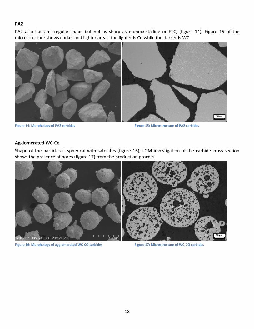
PA2 also has an irregular shape but not as sharp as monocristalline or FTC, (figure 14). Figure 15 of the microstructure shows darker and lighter areas; the lighter is Co while the darker is WC.
Figure 14: Morphology of PA2 carbides Figure 15: Microstructure of PA2 carbides
Agglomerated WC-Co
Shape of the particles is spherical with satellites (figure 16); LOM investigation of the carbide cross section shows the presence of pores (figure 17) from the production process.
Figure 16: Morphology of agglomerated WC-CO carbides Figure 17: Microstructure of WC-CO carbides

19
4.2 Matrix powder
4.2.1 Carbon content and density Measured carbon content and density for the matrix powders presented in table 7.
Table 7: Carbon content and density on matrix powder
Matrix powder lot nr: C % Densitet [g/cm3]
1559-40 1591371 0,029 8,2
1540-00 C57686 0,25 8,1
4.2.2 Melt interval The melt interval for the two matrix powders are analyzed and shown in figure 18. 1559-40 (NiSiB) has a higher melting point than 1540-00 (NiSiCrB).
Melt intervals:
1559-00: 1041°C – 1095°C
1540-00: 1006°C - 1050°C.
Figure 18: Melt interval, matrix powders
Created with NETZSCH Proteus software
[#] Instrument
[1.1] STA 449F3
[2.1] STA 449F3
File
1559-40.ngb-ds3
1540-00.ngb-ds3
Date
2013-06-24
2013-06-20
Identity
1559-40
RT-1400
Sample
1559-40
RT-1400
Mass/mg
26.0
29.4
Segment
1/2
1/2
Range
30/10.0(K/min)/1400
30/10.0(K/min)/1400
Atmosphere
Ar, 50.0ml/min / Ar, 20.0ml/min
Ar, 50.0ml/min / Ar, 20.0ml/min
Corr.
020
020
400 600 800 1000 1200 1400Temperature /°C
-8
-6
-4
-2
0
2
DSC /(mW/mg)
Main 2013-06-24 15:29 User: SEEVDI
Peak: 1034
.5 °C
Onset: 1006
.1 °C
Peak: 1077
.3 °C
Onset: 1041
.6 °C
[1.1]
[2.1]
exo

20
4.2.3 Metallography Figure 16 show the cross section of 1559-40 powder as observed in LOM prior to etching. The particles are spherical in shape and no porosity is observed inside them. 1540-00 powder has similar appearance.
Figure 19:1559-40, NiSiB powder

21
4.4 Process Process parameters The process parameters which results in coating with the desirable properties are presented in table 8.
Table 8: Process parameters
Preheating: 400 °C
Power: 2 kW
Speed: 3mm/s
Overlap 3 mm Powder feeding setting: 5 Carrier gas:
3 – 3,5 l/min
Shield gas: 11 l/min
Powder feeding The powder feeding rates were measured for settings 5 and 7, 7 on the feeding machine. At the low setting are the feeding is between 27 to 33 grams per minute for all powder combinations. Monocristalline powder have highest feeding rate on the low setting even if it have lower density than both spherical and FTC.
Table 9: List of powder feeding rates
Matrix1559-40 Matrix 1540-00 Powder feeding setting: Powder feeding setting: 5 7,7 5 7,7
40% Spherical 29g/min 47 g/min 28 g/min 50% Spherical 30 g/min 48 g/min 28 g/min 50 g/min 60% Spherical 31 g/min 60 g/min 30 g/min
50% FTC 28 g/min 44 g/min 25 g/min 47 g/min 50%Monocristalline 33 g/min 44 g/min 30 g/min 42 g/min 50% Agglomerated 30 g/min 42 g/min 27 g/min 35 g/min
No carb. 24 g/min 27 g/min

22
4.3 Coatings Initial laser cladding experiments showed that PA2 formed a coating with high porosity; the decision was taken to not continue with testing on this carbide type. Metallographic evaluation on PA2 + 1559-40 coatings are presented in Appendix 3.
4.3.1 Dilution Dilution of substrate was measured on 4 samples / material. Higher dilution of substrate is noted on the 1559-40 coatings compared to 1540-00. 60% spherical cast show the highest dilution of substrate.
Figure 20: Dilution on 1559-40 coatings Figure 21: Dilution on 1540-00 coatings
4.3.2 Cracks The amount of cracks is summarized for samples of each coating type welded by identical parameters. Number of cracks per coating type is summarized in table 10; an example of a coating with indicated cracks is presented in figure 23. No cracks are observed in the 1540-00 matrix coatings.
Table 10: Summary of cracks in 1559-40 coatings
Figure 22: A sample with 2 indicated cracks.
0
2
4
6
8
10
12
14
16
0,0
2,0
4,0
6,0
8,0
10,0
12,0
14,0
16,0
%
Cracks in coating 1559-40 + carbides, 4 samples of each material tested.
Effect: 2kW Speed: 3mm/s
Powder feeding: 5
Carbide: Nr. of cracks: 40% Spherical 2 50% Spherical 8 60% Spherical 2
FTC 15 Monocristalline 20 Agglomerated 5
%

23
4.3.3Hardness measurements Coating hardness
Vickers hardness, HV30 on coatings with 1559-40 matrix are presented in figure 23. Agglomerated carbide coating has the highest hardness. Vickers hardness, HV30 on coatings with 1540-00 matrix are presented in figure 24.
Figure 23: Hardness on 1559-40 coatings
Figure 24: hardness on 1540-00 coatings
300
400
500
600
700
800
900HV 30
300
400
500
600
700
800
900

24
Microhardness
Microhardness measurements for all coatings using 1559-40 as a matrix are presented in figure 26. Microhardness is not consistently affected by the addition of carbides indicating a limited dissolution of the carbides them-selves. Microhardness measurements of the matrix show FTC coatings have highest hardness value. This could be due to the different degree of dissolution of the different carbides in the matrix which is higher for FTC and spherical carbides than for the monocristalline WC.
Figure 25: Microhardness in 1559-40 coatings
Microhardness measurements for 1540-00 coatings are presented in figure 27. Microhardness measurements of the matrix in 1540-00 coatings are lower than coatings with 1559-40 matrix in agreement with chemistry and microstructure. Monocrystalline carbide coating shows lowest difference in hardness between the matrixes.
Figure 26: Microhardness on 1540-00 coatings
400
450
500
550
600
650
700
750
800
HV 0,5
0
100
200
300
400
500
600
700
800
Only 1540-00 50% Sphericalcast
50% FTC 50%Monocristalline
50 %Agglomerated

25
4.3.4 Metallography
4.3.4.1 Matrix coatings Coatings only consisting of matrix powder are mapped in light optical microscope (LOM) and scanning electron microscope (SEM).
1559-40 NiSiB Microstructure of the NiSiB matrix coating consists of austenitic primary dendrites, γ-nickel boride eutectic, and nickel-boride nickel-silicide eutectic, figure 27, 28. The chemical composition of elements in the different phases is presented in table 11.
Figure 27: Microstructure of etched NiSiB (1559-40) coating at 100 x. Figure 28: SEM image showing matrix microstructure.
Table 11: Chemical composition in the areas in figure 28.
Field Ni % Si % Fe %
1 95 1 4
2 87 3 10
3 89 7 4
Austenitic primary dendrites austenitic primary dendrites
Austenitic primary dendrites austenitic primary dendrites
γ-nickel boride
Nickel boride – nickel silicide eutectic
1
2
3

26
(a) (b) (c)
(d) (e)
Figure 29: Distribution of elements analyzed by SEM (1559-40)
In figure 29 (a) is the different phases shown in higher magnification, in 29 (b –e) is mappings of the elements presented (green color represents presence of the current element).
Austenite Nickel boride – nickel silicide eutectic
γ-nickel boride

27
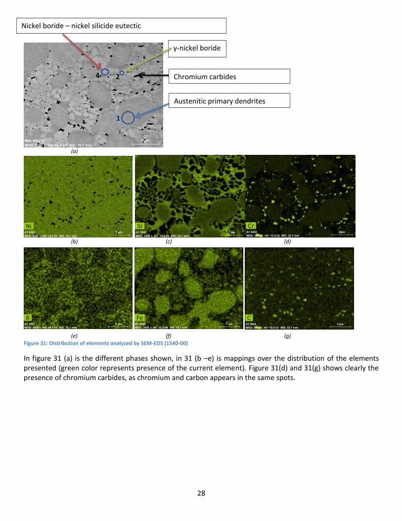
1540-00 NiCrSiB Microstructure of NiCrSiB consists of austenitic primary dendrites, chromium carbides, nickel-nickel boride eutectic and nickel boride-nickel silicide eutectic, figure 30, 31a. More austenite and a coarser microstructure make hardness of this coating lower compared to 1559-40. The chemical composition of elements in the different phases is presented in table 12.
Figure 30: LOM Microstructure of NiCrSiB 1540-00 at 100x.
Table 12: Contents of elements in the SEM analyzed fields in figure 31a.
Field Ni % Cr % Si % Fe %
1 85 8 3 4
2 91 7 - 2
4 88 4 6 2
Austenitic primary dendrites austenitic primary dendrites
28
(a)
(b) (c) (d)
(e) (f) (g)
Figure 31: Distribution of elements analyzed by SEM-EDS (1540-00)
In figure 31 (a) is the different phases shown, in 31 (b –e) is mappings over the distribution of the elements presented (green color represents presence of the current element). Figure 31(d) and 31(g) shows clearly the presence of chromium carbides, as chromium and carbon appears in the same spots.
Chromium carbides
Austenitic primary dendrites austenitic primary dendrites
Nickel boride – nickel silicide eutectic
γ-nickel boride
1
2 4

29
4.3.4.2 Carbide + matrix coatings
40% 50% 60% Spherical cast in 1559-40
Light optical microscope pictures show that the tungsten carbides are more concentrated in the lower part of the coating layer on the 40% carbide samples. Small tendency to sink is also seen in some of the 50% samples, but not as distinctive. The tungsten carbides show a border with a coarser structure than the structure in the inner of the carbides, and there is a difference of the thickness of the border between the 40% 50% and 60% coatings; 40% carbide coating have a larger border and the 60% coating a smaller.
Figure 32: 40% spherical cast. Figure 33: 50% spherical cast . Figure 34: 60% spherical cast.
Figure 35: 40% spherical cast . Figure 36:50% spherical cast . Figure 37: 60% spherical cast.
Figure 38 shows the SEM-EDS analyzed fields, and the content of the fields is presented in table 13. The border of the carbide consists mostly of W rich carbides (field 4) with matrix material in between. C is not presented in this analysis as it cannot be quantified by EDS. Matrix outside the carbide (field 1) holds near 9 % W; this confirms some melting of the carbides in the laser process.
Interface between matrix and carbide

30
Figure 38: SEM analyzed fields.
Table 13: SEM analysis of fields in 50% Spherical Cast + 1559-40
Field W % Ni % Si % Fe %
1 8 84 3 5
2 100 - - -
3 89 8 - 3
4 98 1 - 2
MAG: 3000x HV: 5kV WD: 10,2 mm
Carbide precipitated from W and C enriched matrix
Example of area affected by heat from cladding process Dissolution of WC/W2C and re-precipitation of W rich carbides
31
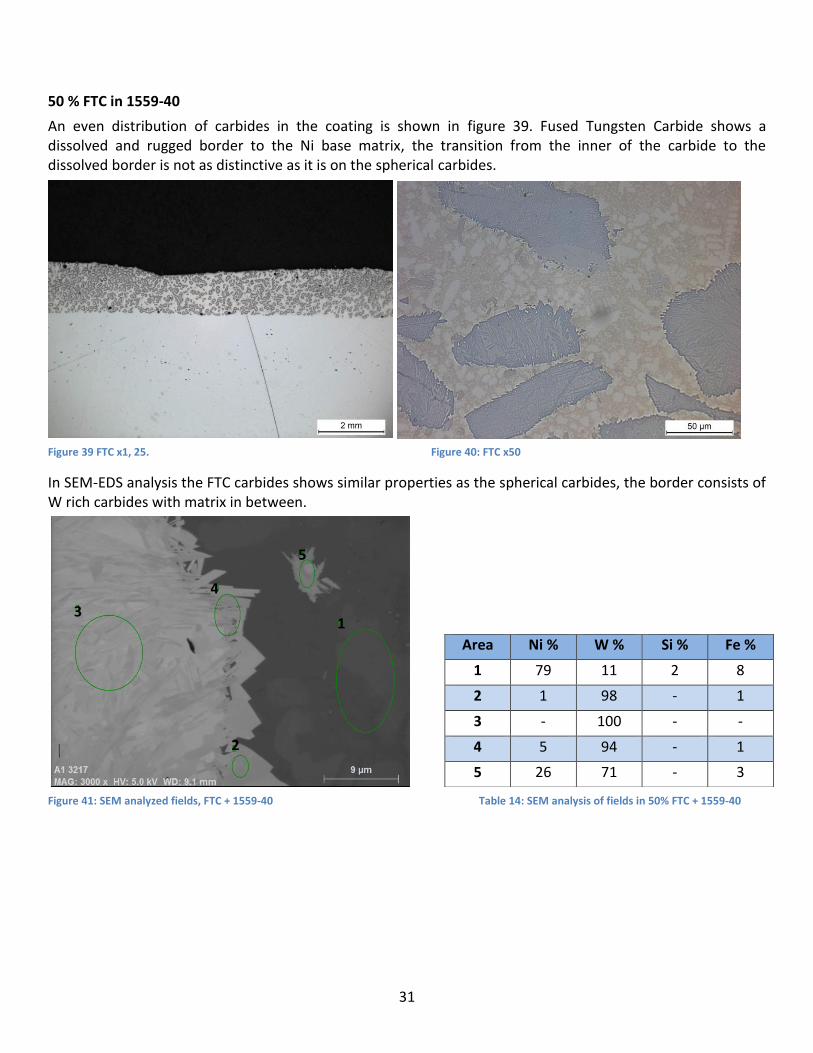
50 % FTC in 1559-40
An even distribution of carbides in the coating is shown in figure 39. Fused Tungsten Carbide shows a dissolved and rugged border to the Ni base matrix, the transition from the inner of the carbide to the dissolved border is not as distinctive as it is on the spherical carbides.
Figure 39 FTC x1, 25. Figure 40: FTC x50
In SEM-EDS analysis the FTC carbides shows similar properties as the spherical carbides, the border consists of W rich carbides with matrix in between.
Figure 41: SEM analyzed fields, FTC + 1559-40 Table 14: SEM analysis of fields in 50% FTC + 1559-40
Area Ni % W % Si % Fe %
1 79 11 2 8
2 1 98 - 1
3 - 100 - -
4 5 94 - 1
5 26 71 - 3
1
2
3
4
5

32
50 % Monocristalline tungsten carbide in 1559-40
Monocristalline WC carbides have a very sharp edge and do not show any dissolved borders. Some porosity and a higher carbide concentration in the lower part of the coating are visible at the low magnification picture 42. Overlap areas shows a bit lower carbide amount than the rest of the cross section. The cracks and brittle structure this carbide have, is looking the same after welding as it did before, figure 43.
Figure 42: Monocristalline x1, 25 Figure 43: Monocristalline x50
In SEM analysis tungsten is identified in the matrix between the carbides as seen in table 15, field 1. The undissolved and sharp borders of the carbides is seen in figure 44.
Figure 44: SEM analyzed fields, Monocrystalline carbide
Table 15: SEM analysis of monocristalline coating
Field Ni % W % Si % Fe %
1 91 3 3,6 2,6
2 1 98 - 1
3 94 2 4 -
3
1 2

33
In the mapping of elements distribution the sharp border between carbide and matrix is very distinct, figure 45. Lower amounts of W exist in the matrix and are shown in figure 45(c) as dark green color in the black matrix.
(a) (b) (c)
Figure 45: Distribution of elements: (a) Picture of carbide + matrix; (b) Ni, (c) W

34
50 % Agglomerated WC-Co in 1559-40
Agglomerated WC-Co shows some porosity in the coating, the carbides are evenly distributed in the full height of the coating except from overlap areas where higher carbide dissolution is visible, figure 46(a-b).
(a) (b) Figure 46: (a) Agglomerated WC-Co, x1, 25; (b) Agglomerated WC-Co, x50
SEM-EDS analysis shows in figure 47 and table 16 that cobalt is dissolved in the matrix and the matrix have filled the gaps between the carbides. For some reason a high iron content is seen in this analysis even though the earlier X-ray diffraction (XRD) measurements resulted in a dilution of the substrate at 4,5% on this specific sample. This may indicate that there are some variations in dilution of substrate over the coating.
Figure 47: SEM analyzed fields Agglomerated WC-Co
Area Ni % W % Co % Si % Fe %
382 60 7 6 3 24
383 60 3 7 3 27
384 10 83 1 - 6
385 68 1 7 2 22
386 3 94 1 - 2
Table16: SEM analysis of fields in Agglomerated WC-Co + 1559-40
386
385
384
383
382

35
50% Carbides in 1540-00
50 % Spherical cast carbide in 1540-00 The carbides are evenly distributed in the coating except from the overlap areas where the carbides seems to be more dissolved, surface of the coating is even in the overlap areas. In figure 49 the dissolved border zone of the carbides looks very thin. However, dissolution of the carbides has taken place as the amount of carbides in the matrix has increased (carbide in matrix marked in fig 49). Most probably it is tungsten chromium rich carbides but this should be verified by EDS. The morphology of the interface between the 1559-40 and 1540 matrixes and the tungsten carbides is different. For 1559-40 the interface area is thicker and W rich carbides are precipitated on it. For 1540 the primary carbides formed due to dissolution of the tungsten carbides are more evenly distributed in the matrix.
Figure 48: Spherical cast + 1540-00, x1, 25 Figure 49: Spherical cast + 1540-00, x50
50 % FTC in 1540-00 Carbides are evenly distributed in the coating, and the coating surface is even in the overlap areas ,figure 50, 51. The lower area amount of carbides reported for 1540-00 coatings are clearly visible. Behavior is similar to spherical carbides in 1540-00.
Figure 50: FTC carbide + 1540-00, x1, 25 Figure 51: FTC carbide + 1540-00, x50

36
50 % Monocristalline tungsten carbide in 1540-00 The monocristalline carbides show a clear tendency to sink more in 1540-00 coating (figure 46). Carbide borders looks ragged and more dissolved on the borders as seen in higher magnification in figure 53.
Figure 52: Monocristalline carbide + 1540-00, x1, 25 Figure 53: Monocristalline carbide + 1540-00, x50
50 % Agglomerated WC-Co in 1540-00 50% Agglomerated carbide in 1540-00 got porosity in the coating (figure 54). In the overlap area the carbides are more dissolved due to the thermal impact in this area.
Figure 54: Agglomerated + 1540-00, x1, 25 Figure 55: Agglomerated + 1540-00, x50

37
4.3.5 Area fractions Area fractions of carbides in the crosscut of the coating are presented in figure 56 (1559-40 coating) and figure 57 (1540-00) coating. Principle for area fraction measurements is presented in figure 58.
Figure 56: Area fraction of carbides in 1559-40 coatings
Figure 57: Area fraction of carbides in 1540-00 coating
05
101520253035404550
0
5
10
15
20
25
30
35
40
45
50
50% Sphericalcast
50% FTC 50%Monocristalline
50%Agglomerated
%
%

38
Volume fraction With the densitys of each powder known, the volume fraction of carbides are calculated for each powder mix (table 16): Table 16: Volume fractions of carbides
Weight % Vol. % carbides
40% Spherical 25%
50% Spherical cast 33%
60% Spherical cast 43%
50% FTC 33%
50% Monocristalline 35%
50% Agglomerated 36%
Figure 58: Principle of area measurements (10 pictures along the cross section are analyzed with image analysis).

39
4.3.6 Changing process parameters Increasing the laser power from 2kW to 3kW and keeping the all other process setting the same results in a higher dilution of substrate, dilution is around 19% for these settings for spherical carbides in 1559-40 powder. Increasing the speed from 3 mm/s to 5-and 7 mm/s with all other parameters left as they were results in a thinner coating and only a small increase in dilution.
Proportional increased process parameters Process parameters are increased proportional to each other, and tests done on following parameters:
Table 17: Increased process parameters
Preheating: 400 °C
Power: 3,3 kW
Speed: 5 mm/s
Overlap 3 mm Powder feeding setting: 7,7 Carrier gas:
3 – 3,5 l/min
Shield gas: 11 l/min
Dilution as result of changes in process parameters
Dilutions shows a little increased values at high process settings.
Figure 59: Dilution at different process settings
Microhardness as result of higher process parameters
Microhardness on coatings produced by higher process settings are presented in figure 60. Coatings with agglomerated carbides show a high porosity for these process settings and are not possible to measure hardness on. Hardness values are similar to the values on the coatings made by the lower process settings.
0
2
4
6
8
10
12
14
2kW, 3mm/s,Powder feed 5
3,3kW,5mm/s,Powder feed7,7
%

40
Figure 60: Microhardness on coatings at: 3,3kW, 5 mm/s, Powder feeding 7, 7
Area fractions as result of process parameters
Coatings with agglomerated carbides show a high porosity and are not possible to measure.
Figure 61: Area fractions of carbides at result of different process settings
400
450
500
550
600
650
700
750
50% Spherical cast 50% FTC 50% Monocrystalline
HV 0,5
0
5
10
15
20
25
30
35
40
45
40% Spherical 50% Spherical 60% Spherical FTC Monocrystalline
2 kW,3mm/s,Powderfeeding 5
3,3kW,5mm/s,Powderfeeding 7,7
%

41
4. 5 Wear
4.5.1 Wear test results Results of ASTM G65 – 4 Procedure are presented in figure 62; columns represent the average volume loss, and the dots represent the scatter of the results. Specification of wear test samples and values of average volume loss are reported in appendix 4. For coatings with 50% carbides the volume loss is 8, 02 mm3 for spherical, 8, 26 mm3 for monocristalline and 8, 73 mm3 for FTC. For the agglomerated the volume loss are at 21, 4 mm3. Monocristalline have the lowest scatter of the coatings with 50 % carbides.
Figure 62: Results of ASTM G65 Procedure A wear test results
1,00
1,10
1,20
1,30
1,40
1,50
1,60
1,70
1,80
1,90
2,00
0
5
10
15
20
25
Scat
ter
AV
L P
10/
P9
0
AV
L P
50 (
mm
3)
EN 235 JR steel blank + Laser cladded 1559-40 + ...
ASTM G65 Procedure A

42
4.5.2 Metallography wear tests Only samples with 50 % carbides are prepared as metallography samples. Cross sections of the worn samples are presented in figure 63 – 66, wear track are between the blue lines. The spherical, FTC and Monocristalline coatings show an even carbide distribution and a quite even worn surface. Monocristalline seems a bit rougher than the other two. Agglomerated coating shows a higher porosity than some of the other metallography samples of agglomerated WC-Co + 1559-40 and also areas with big volume loss.
Figure 63: 50% Spherical cast, x1, 25
Figure 64: 50 %FTC, x1, 25
Figure 65:50 % monocristalline, x1, 25
Figure 66: 50% Agglomerated, x1, 25

43
Figure 67 – 70 show the cross sections of the worn samples at 5x magnification.
Figure 67: Spherical cast Figure 68: FTC
Figure 69: Monocristalline Figure 70: Agglomerated
Agglomerated WC-CO has higher mass loss in overlap areas (figure 71) due to porosity and dissolution of carbides in these areas (figure 72).
Figure 71: Agglomerated, overlap area, x5 Figure 72: Agglomerated, overlap area, x50

44
SEM investigation of worn surfaces are presented in figure 73 -76 (300x) and 77-80 (1100x).
Figure 73: Spherical cast Figure 74: FTC
Figure 75 : Monocristalline Figure 76 : Agglomerated
Even after wear tests shows the monocristalline carbides a sharp border to the matrix, (figure 79). Spherical cast carbides, figure 77 show a more homogeneous structure than the FTC carbide, figure 78. In figure 76 and 80 it is seen how the small 1 µm carbides the agglomerated consists of have been ploughing through the matrix during the wear test and on this coating is the matrix not worn down between the carbides.
Figure 77: Spherical cast Figure 78: FTC

45
Figure 79: Monocrystalline Figure 80: Agglomerated
At high magnification cracks are observed in WC carbides (figure 81); this can even be distinguished on the 1 µm WC carbides in the agglomerated powder at high magnification in figure 82.
Figure 81: Cracks in monocristalline carbide Figure 82: Agglomerated, cracks in the 1 µm WC carbides

46
5. Discussion 40% 50% 60% Spherical cast in 1559-40 A tendency of increased dilution for increased carbide amount in the powder can be observed on the dilution measurements. Both microhardness and coating hardness are highest on 60% coatings due to the higher amount of carbides. In 40% and 50% coatings the deviation of measured values is bigger and average hardness is a little higher on 40% coatings, but due to the deviation it’s not sure if always is like this. Observed on the crosscut carbides are more concentrated in the bottom area of the coating with 40% carbides, and some tendency to this is observed in some of the samples with 50% spherical cast as well. The reason for carbides sinking is that the density of the carbides is higher than that of the nickel based matrix material. Coatings with 60% carbides have a dense carbide distribution as there is no space for them to sink. Few pores are observed in the spherical carbide coatings. The tungsten carbides show a border with a coarser structure than the structure in the inner of the carbides. Due to the heat generated during the laser cladding process partial dissolution of the tungsten carbides take places in the melt pool followed by the precipitation of new tungsten rich primary carbides at the interface between the carbides and the nickel based matrix as well as in the matrix it-self. Comparing the carbides a difference in the dissolved border of the carbides can be seen, carbides in coatings containing 40% carbides have a larger dissolved border zone and the 60% coatings has the smallest dissolved border. According to thermodynamics the driving force for dissolution of tungsten carbides decreases with raised amount of tungsten carbides in the melt. Area fraction measurements show carbide fractions close to the nominal calculated volume fraction for respective coating, this indicates that there is a low dilution of the carbides process.
50% Carbides in 1559-40
PA2 carbide coatings have a high amount of pores and are because of this not useable for laser cladding. Some porosity exists in coatings with agglomerated and monocristalline carbides.
Spherical, FTC and agglomerated carbides are evenly distributed in the coating cross section, monocristalline show a tendency of sinking. Overlap areas, especially in agglomerated and monocristalline carbide coatings have a lower amount of carbides due to dissolution, as this area are affected by the laser beam when the overlapping track is welded. The cracked and brittle structure monocristalline carbides have is looks the same after welding as it did before.
The coating with most cracks is the one with monocristalline carbides, this carbide had a cracked structure even before welding so it could have some connection with the cracks in the coating. Monocrystalline carbides do also has the sharpest and pointiest shape; this gives a lot of points where a crack could be initiated. FTC carbide coatings show second most cracks and this is also a carbide type with a sharp and pointy shape. Spherical carbides have a better geometry when it comes to avoiding crack initiations and also shows a smaller number of cracks. Agglomerated carbide coatings show no cracks. Average dilution is higher on spherical and FTC, close to 10%. Agglomerated shows the lowest dilution at 3, 8 %.
According to the hardness measurements agglomerated carbide coatings have the highest coating hardness and the lowest matrix micro hardness. The high coating hardness is probably due to the high amount of 1 µm WC carbides this powder actually consists of become well distributed in the coating and gives a fine and hard structure. Coating hardness is not measured in the overlap areas where there is a higher dissolution of carbides, here the hardness is probably lower. Micro hardness is probably low due to low dissolution of carbides into the matrix, as agglomerated WC-Co only consists of the thermodynamically more stable WC carbide. The same phenomena with the micro hardness can be observed on monocristalline coatings which also have low carbide dissolution and low micro hardness.
Low carbide dissolution on the monocristalline carbides compared to the eutectic ones can be seen in the metallographic analysis where they show very sharp edges and no dissolved borders as the eutectic W2C/WC

47
carbides does. Even in SEM pictures at 3000 times magnification the edge of the monocristalline carbides looks sharp, but when analyzed some W is found in the matrix between the carbides, which proves some dilution of the carbides, but compared to the other coatings monocrystalline coatings have a lower tungsten content in the matrix.
FTC carbide coatings have a more rugged border compared to the spherical carbides but otherwise their carbide-matrix interface seems similar. SEM analysis show matrix in FTC coating holds 11% W and Spherical coating matrix 8 % W, the carbide border also consists of the same type tungsten rich carbide, which confirm their similarities.
Changed process settings
Increasing only the laser mainly results in an increased dilution of the substrate, increasing only the speed gives thinner coatings as described in literature. When all process parameters are increased proportional to each other to give the same heat input at a higher speed, the resulting coating properties are a few percent increased dilutions thicker. Area fraction measurements indicates the carbides are more dissolved, but micro hardness are about the same. Agglomerated carbide coatings show a high porosity on these process settings, and it can be concluded that this type of carbide needs a low heat input to give desirable results.
Wear testing
For 40%, 50% and 60% the result show that increased amount of carbides gives increased wear resistance as also considered in [8], approximately 20% lower volume loss per 10% step increase in carbide amount is the result in this test.
For 50% carbide coatings spherical carbides show best wear resistance close followed by monocristalline and FTC. Agglomerated have a high volume loss, mainly in the overlap areas where some porosity exists and carbides are more dissolved. In the rest of the agglomerated coating a very even surface with a fine distribution of carbides is presented, due to the small carbides the surface roughness becomes lower.
When comparing worn surfaces in 5x magnification it seems like the spherical carbides are well bonded to the matrix as they remain in the coating even when they have a very small contact area. This can also depend on the higher hardness of the spherical carbides, as the carbides in the other coatings seem more worn down. Monocristalline coating show a rougher worn surface as the matrix seem softer and more worn, this is confirmed by the lower matrix hardness and carbide dissolution on this material.
Investigating the worn carbides in SEM, the spherical carbides show larger border zone and a smoother transition to the matrix. Monocrystalline carbides have a sharp transition to the matrix. FTC is somewhere in between these two. Agglomerated coating behaves a bit different as the size of the carbide is much smaller than for the others and here it seems like carbides are torn out and making grooves in the matrix. At high magnification in SEM the cracks in monocristalline WC carbides can be seen and confirm the brittleness of this type. Interesting to note is cracks also exists in the 1µm WC carbides in the agglomerated coatings.
The scatter of volume loss has a connection to the scatter on the coating hardness values; materials with a large scatter in hardness also have a large scatter in volume loss.
Influence of Chromium in matrix powder
The micro and macro hardness of this coating are lower are lower, and no cracks are observed in coatings with 1540-00, the lower hardness of these coatings makes them less sensitive to cracking. Porosity are present in the agglomerated carbide coatings.

48
Carbides in coatings with 1540-00 matrix have a more distinct edge and no dissolved border as carbides in 1559-40 have, but it seems like carbides are more dissolved compared to 1559-40. When comparing coatings consisting of only 1540-00 base powder and coatings consisting of carbides + 1540-00, new formed carbides can be seen in the matrix. Area fraction measurements confirm a higher dissolution of carbides as the area fractions generally are lower on 1540-00 coatings. Dilutions of substrate are generally 3%-4% lower on 1540-00 coatings. This makes it possible to make this conclusion: chromium in the matrix powder increases the carbide dissolution and decreases dilution of substrate.

49
6. Conclusions Process
• It is possible to obtain similar coating properties with different process parameters
• PA2 carbides are not suitable for laser cladding
• Agglomerate carbides give porosity in the coating more easily and have a smaller process window in which it is possible to obtain coatings with the desirable properties.
Material
• Monocrystalline carbide coatings tend to crack more than the others and have a low carbide dissolution in the matrix.
• Agglomerate carbide coatings are less sensible to crack.
• Chromium increases the carbide dissolution and decreases the substrate dilution
• No cracks with 1540-00 NiCrSiB matrix
• Decreased dilution for increased carbide amount
• Less affected interface carbide matrix with increased carbide amount
Wear
• Spherical carbides have highest carbide hardness and also highest wear resistance with a smal margin to FTC and monocrystalline coatings.
• Increased carbide amount gives increased wear resistance
• Agreement between scatter in hardness and wear
• Monocristalline carbide coatings get a rougher worn surface
• Agglomerated coatings are advantageous in applications with demand on low surface roughness

50
7. Future work For the future wear tests on 1540-00 coatings should complement this report, as it was not possible to do during the time for this project due to the time consuming sample preparation.
It is seen in this project that chromium influences the carbide dissolution and probably the behavior of the melt pool, a study on chromium’s influence could possibly explain how this works. As this project only focuses on mainly one carbide size, a survey on how different carbide sizes affects the wear properties could help finding the optimal composition for high wear resistance.
Agglomerated WC-Co shows some really good wear resistance characteristics in some parts of the coating and not so good in the overlap areas, this is probably due to the thermal impact there. Probably it is possible to optimize the process parameters so these overlap areas come with better properties. This can possibly give some new and interesting areas of use for this powder type, especially in applications where low surface roughness is preferable.
The method with image analysis for measure the area fraction of the carbides in the coating is not very reliable, so this method needs some development to be more reliable.
The method Plasma Transferred Arc is the alternative to laser cladding, and it should be interesting to see if the carbide types behave in different ways in this process.

51
References
Books
[1] Höganäs handbook for thermal spray surfacing – PTA surfacing 3d edition, Höganäs AB, 2012
[2] Hugh O. Pierson, 1996, Handbook of refractory carbides and nitrides, New Jersey, Noyes publications, ISBN -8155-1392-5 (s. 100-104, 113-115)
[3] Jarfors m.fl., 2010 Tillverkningsteknologi, upplaga 4:1, Studentlitteratur, Lund, ISBN 978-91-44–070391
[4] Klas Weman, 2010, Karlebo svetshandbok, Liber, Stockholm, fjärde utgåvan, ISBN 978-91-47–09939-9
[13] Anton van Beek, 2009, Advanced engineering design, ISBN 978-90-810406-1-7]
[17] Karl Björk former och tabeller för mekanisk konstruktion, sjätte upplagan, Karl Björks Förlag, Stockholm
Articles
[5] “Analysis of coaxial laser cladding process” U. de Oliveira, V. Ocelı´k, J.Th.M. De Hosson
[6] Laser cladding R. Vilar, Departamento de Engenharia de Materiais, 1998, Instituto Superior Te´cnico, Lisboa, Portugal [7] HIGH POWER DIRECT DIODE LASER CLADDING OF STELLITE 6WC COATINGS Ph.D. Eng. Janicki D. Silesian University of Technology, Faculty of Mechanical Engineering, welding Department – Gliwice, Poland
[8] Influence of tungsten carbide particle size and distribution on the wear resistance of laser clad WC/Ni coatings, K. Van Acker et al. / Wear 258 (2005) 194–202
[9] Abrasive wear performance and microstructure of laser clad WC/Ni layers; [S.W. Huanga, M. Samandi a, M. Brandt [10] Review on Laser Deposition Welding; Stefan Kaierle, Alexander Barroi, Christian Noelke, Joerg Hermsdorf,
Ludger Overmeyer, Heinz Haferkamp, Laser Zentrum, Hannover, Germany]
[11] Influence of WC particle behavior on the wear resistance properties of Ni–WC composite coatings” P.
Wu∗, H.M. Du, X.L. Chen, Z.Q. Li, H.L. Bai, E.Y. Jiang Institute of Advanced Materials Physics, School of Science, Tianjin University, Tianjin China, 2003”
[12] “Effect of carbide degradation in a Ni-based hardfacing under abrasive and combined impact/abrasive conditions.” C. Katsich, E, Badisch, AC2T research GmbH, Viktor Kaplan-Strasse 2, 2700 Wiener Neustadt, Austria.
Internet [14] http://www.astm.org/Standards/G65.htm, [2013-10-03] [15] Höganäs surface coating product data
[16] http://www.isletme-ltd.com.tr/kataloglar/woka/10-699_WOKA_Welding_Powders.pdf [2013-10-03]

52
Appendix 1: W-C phase diagram

53
Appendix 2 - Size distribution of carbide powders
Figure 83, Spherical cast carbide (4590)
Figure 84, FTC (4570)
Figure 85, Monocristalline carbide powder (4580)
0
10
20
30
40
50
60
70
80
90
100
Cum
ula
tive
dis
trib
ution Q
3 / %
0
1
2
3
4
5
6
Den
sity
dis
trib
utio
n q
3*
0.4 0.6 0.8 1.0 2 4 6 8 10 20 40 60 80 100 200
particle size / µm
0
10
20
30
40
50
60
70
80
90
100
Cum
ula
tive
dis
trib
ution
Q3
/ %
0.0
0.5
1.0
1.5
2.0
2.5
3.0
3.5
Den
sity
dis
trib
ution
q3
*0.4 0.6 0.8 1.0 2 4 6 8 10 20 40 60 80 100 200
particle size / µm
0
10
20
30
40
50
60
70
80
90
100
Cum
ula
tive
dis
trib
ution Q
3 / %
0.0
0.5
1.0
1.5
2.0
2.5
3.0
3.5
4.0
Den
sity
dis
trib
ution q
3*
0.4 0.6 0.8 1.0 2 4 6 8 10 20 40 60 80 100 200
particle size / µm

54
Figure 86, PA2 powder (WC-Co)
Figure 87, Agglomerated WC-Co (44712-10)
0
10
20
30
40
50
60
70
80
90
100
Cum
ula
tive
dis
trib
ution Q
3 / %
0.0
0.5
1.0
1.5
2.0
2.5
3.0
3.5
Den
sity
dis
trib
ution q
3*
0.4 0.6 0.8 1.0 2 4 6 8 10 20 40 60 80 100 200
particle size / µm
0
10
20
30
40
50
60
70
80
90
100
Cum
ula
tive
dis
trib
ution Q
3 / %
0.0
0.5
1.0
1.5
2.0
2.5
3.0
3.5
4.0
4.5
5.0
Den
sity
dis
trib
ution q
3*
0.4 0.6 0.8 1.0 2 4 6 8 10 20 40 60 80 100 200
particle size / µm

55
Appendix 3 –PA2 Metallographic evaluation
PA2
PA2 coating shows a high porosity, but has an even distribution of the carbides. Due to the high porosity the conclusion was to not proceed with wear tests or further welding tests on this carbide.
(a) (b) Figure 88: (a) PA2 x1, 25; (b) PA2 x50
Despite porosity the carbides are quite intact after welding, but it is just the small 1µm WC carbides that hold their formation, the cobalt these carbides are cemented with is dissolved in the matrix as seen in field 3 in the SEM analysis.
(a) (b) Figure 89: (a) SEM picture 700x; (b) SEM analyzed fields.
Table 3: SEM analysis of fields in PA2 + 1559-40
Field Ni % W % Co % Si % Fe %
1 3,4 95,5 1,1 - -
2 32,9 65,0 2,0 - 0,1
3 80,0 7,9 7,9 4,1 -
4 6,5 92,0 1,3 - 0,3

56
In SEM analysis of distribution of elements its seen cobalt is well integrated with the matrix and the matrix has filled the areas between the carbides. Cobalt and nickel have about the same melting point (Co 1495°C and Ni 1455°C).
(a) (b) (c)
(d) (e) (f)
Figure 90: Distribution of elements: (a) Picture of carbide + matrix; (b) Ni, (c) W, (d) Fe, (e) Co (f) C
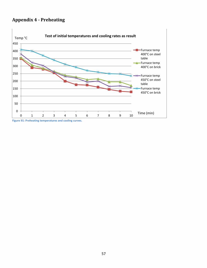
57
Appendix 4 - Preheating
Figure 91: Preheating temperatures and cooling curves.
0
50
100
150
200
250
300
350
400
450
0 1 2 3 4 5 6 7 8 9 10
Furnace temp400°C on steeltable
Furnace temp400°C on brick
Furnace temp450°C on steeltable
Furnace temp450°C on brick
Test of initial temperatures and cooling rates as result
Time (min)
Temp °C

58
Appendix 5 – Wear
Properties on wear test samples
Table 18: Properties on the wear test samples.
Properties on wear test samples
Dilution Cracks Microhardness HV
0,5 Coating hardness
HV 30
40% Spherical 7,5 2 558 712 50% Spherical 10,4 6 553 642 60% Spherical 10,4 2 566 761 FTC 7,6 10 619 766 Monocrystalline 8,6 7 580 651 Agglomerated 4,9 5 627 799
Average volume loss
ASTM G65 Procedure A: average volume loss for 1559-40 + carbide coatings.
EN 235 JR steel blank + Laser cladded 1559-40 + ...
Average Volume Loss [mm3] Scatter
40% Spherical cast 9,40 1,33
50% Spherical cast 8,02 1,32
60% Spherical cast 6,64 1,12
50% FTC 8,73 1,22
50% Monocrystalline 8,26 1,15
50% Agglomerated 21,40 1,48

59
Appendix 6 - Additional pictures of wear test samples Wear border zones, (x5)
Figure 92: Spherical cast Figure 93: FTC
Figure 94: Monocrystalline Figure 95: Agglomerated

![Harekrushna Sutar , Debashis Roy2, Subash Chandra …file.scirp.org/pdf/MSA_2016032117001945.pdfH. Sutar et al. 172 based al loys, and carbides of cer amic and tungsten [1] [2]. Several](https://img.pdfslide.net/doc/110x75/5b3c3d2a7f8b9a986e8cdd94/harekrushna-sutar-debashis-roy2-subash-chandra-filescirporgpdfmsa-sutar.jpg)