Embed Size (px)
Citation preview

Missouri University of Science and Technology Missouri University of Science and Technology
Scholars' Mine Scholars' Mine
International Conferences on Recent Advances in Geotechnical Earthquake Engineering and Soil Dynamics
2010 - Fifth International Conference on Recent Advances in Geotechnical Earthquake
Engineering and Soil Dynamics
26 May 2010, 4:45 pm - 6:45 pm
Effect of Uplift Modelling on the Seismic Response of Shallow Effect of Uplift Modelling on the Seismic Response of Shallow
Foundations Foundations
Liam Wotherspoon University of Auckland, New Zealand
Michael Pender University of Auckland, New Zealand
Follow this and additional works at: https://scholarsmine.mst.edu/icrageesd
Part of the Geotechnical Engineering Commons
Recommended Citation Recommended Citation Wotherspoon, Liam and Pender, Michael, "Effect of Uplift Modelling on the Seismic Response of Shallow Foundations" (2010). International Conferences on Recent Advances in Geotechnical Earthquake Engineering and Soil Dynamics. 17. https://scholarsmine.mst.edu/icrageesd/05icrageesd/session05/17
This work is licensed under a Creative Commons Attribution-Noncommercial-No Derivative Works 4.0 License.
This Article - Conference proceedings is brought to you for free and open access by Scholars' Mine. It has been accepted for inclusion in International Conferences on Recent Advances in Geotechnical Earthquake Engineering and Soil Dynamics by an authorized administrator of Scholars' Mine. This work is protected by U. S. Copyright Law. Unauthorized use including reproduction for redistribution requires the permission of the copyright holder. For more information, please contact [email protected].
Paper No. 5.12a 1
EFFECT OF UPLIFT MODELLING ON THE SEISMIC RESPONSE OF
SHALLOW FOUNDATIONS Liam Wotherspoon Michael Pender University of Auckland University of Auckland Auckland, New Zealand Auckland, New Zealand ABSTRACT This paper presents the development and response of a numerical model for the representation of uplift and reattachment of shallow foundations using the Ruaumoko non-linear dynamic analysis software. Vertical loads carried by the foundation were used to control the rotational and horizontal characteristics, as the stiffness of all degrees of freedom must reduce as the footing progressively detaches from the underlying soil. This culminates in the representation of total uplift, where the foundation provides no stiffness in any degree of freedom until vertical loads become compressive again. Through extension of the capabilities of Ruaumoko, this response was able to be represented. The response of a simple elastic two bay frame structure with shallow foundations attached to the base of each column of the frame was evaluated when subjected to dynamic loads. Various approaches for the definition of the stiffness characteristics of the foundations are presented, as well as the methodology used to represent the effect of uplift. Uplift modeling was shown to have a significant effect on the shear and bending moment in the structural columns. If the point of detachment and reattachment of the foundation was at different horizontal and/or rotational displacements the result was residual horizontal and rotational displacements at the end of loading. This shift in displacement occurred in conjunction with a shift in shear and moment in the columns. INTRODUCTION A range of methodologies have been used to represent the characteristics of shallow foundations. The most basic method uses uncoupled spring elements to represent the properties of the foundation in each degree of freedom. The Winkler approach assumes a bed of closely spaced discrete linear elastic springs. Due to the discrete nature of the springs the displacement at a point related only to the contact pressure at that point, with displacement of each spring independent of each other. This simplifies the actual situation because of the lack of continuity between each point beneath the foundation. The macro element approach (Paolucci 1997, Cremer et al. 2001, Gajan et al. 2005, Pender et al. 2007) uses a single element to represent the non-linearity and coupling between degrees of freedom. Bounding surfaces are used to define the non-linear foundation behavior. The most rigorous method for the representation of shallow foundation characteristics is the use of finite element methods to discretise the soil layer, which can provide the most detailed representation at the expense of increased computation time.
Focusing on the Winkler method, the beam on non-linear Winkler foundation (BNWF) extends the Winkler model with the inclusion of the non-linear properties of the foundation system. Using results from 1g cyclic loading on shallow foundations, Bartlett (1976) developed analytical Winkler based models using elastic-perfectly-plastic springs with uplift capabilities. Good comparisons were made between the analytical and experimental results using this approach. Weissing (1979) also used elastic-plastic springs to represent the compressive behavior of the soil from his similar experimental work. Coulomb slider elements were used to capture the uplift of the foundations. Nakaki and Hart (1987) used elastic springs and viscous dampers in their Winkler model at the base of a shear wall. Chaallal and Ghlamallah (1996) and Filiatrault et al. (1992) modeled the non-linear behavior of both the structural and foundation systems during seismic excitation. The foundation was represented by a Winkler spring bed. The springs were modeled to represent compressive yield and detachment at the point of uplift. Rocking stiffness of the footing was calculated
Paper No. 5.12a 2
and used to develop the vertical stiffness of the system. FEMA 273 (1997), Harden et al. (2005), ASCE 41-06 (2007) and Raychowdhury and Hutchinson (2009) presented spring models that represent the vertical and rotational stiffness of shallow foundations using vertical spring beds with varying stiffness characteristics. The stiffness of the end zones of the foundation were increased, resulting in a larger rotational stiffness. Allotoy and El Naggar (2008) explore the limitations and strengths of the FEMA 273 model, a vertical spring bed with a single horizontal spring. This model was shown to provide a good representation of experimental data except for the vertical deformation of the foundation. This paper presents the development and response of an numerical model for the representation of uplift and reattachment of shallow foundations using the Ruaumoko non-linear dynamic analysis program (2005). The uncoupled spring and the Winkler spring bed approach are used to represent the foundations. A range of methodologies to define the characteristics of the spring bed are presented and their moment-rotation characteristics compared. In order to highlight the effects of uplift on response, other non-linear aspects of the foundation are ignored (ie. soil compliance). A selection of these models is used in the integrated modelling of structure and foundation systems under seismic loading. Shallow foundation models are incorporated into a model of a two bay frame structure. Using this integrated model, the effect of different levels of uplift on the distribution of actions in the structure is presented, along with the variation of characteristics across each foundation. The effect of the uplift model on the response of the structure-foundation system is then presented in terms of the actions at the base of the structural columns and how they compare with a fixed base structural model without any foundation representation. SHALLOW FOUNDATION SPRING MODELS The generally preferred model for the elastic behavior of a shallow foundation is to assume that the soil is an elastic half space. Solutions for the stiffness characteristics of this case have been developed by Gazetas and his colleagues (Gazetas et al. 1985; Gazetas and Tassoulas 1987; Hatzikonstantinou et al. 1989). Using these solutions, the elastic stiffness of a rigid foundation can be represented by single vertical, horizontal and rotational springs. However, this approach is unable to represent the coupling between the degrees of freedom and the reduction in stiffness of all degrees of freedom due to uplift. If a bed of springs is used to represent the foundation it can develop both the vertical (KV) and rotational (Kθ) stiffness. Using the elastic half space solutions, the stiffness of a bed of vertical springs can be set to the stiffness of a rigid footing resting on an elastic half space. Total vertical stiffness can then be distributed to the vertical springs according to the tributary base area of each spring. From this, vertical springs offset from the centre of the foundation will provide some rotational stiffness. If an infinite number of springs are used to
0 1 2 3 4 5 60
2
4
6
8
Footing Width (m)
Rat
io o
f Rot
atio
nal t
o Ve
rtica
l Stif
fnes
s
Spring BedGazetas
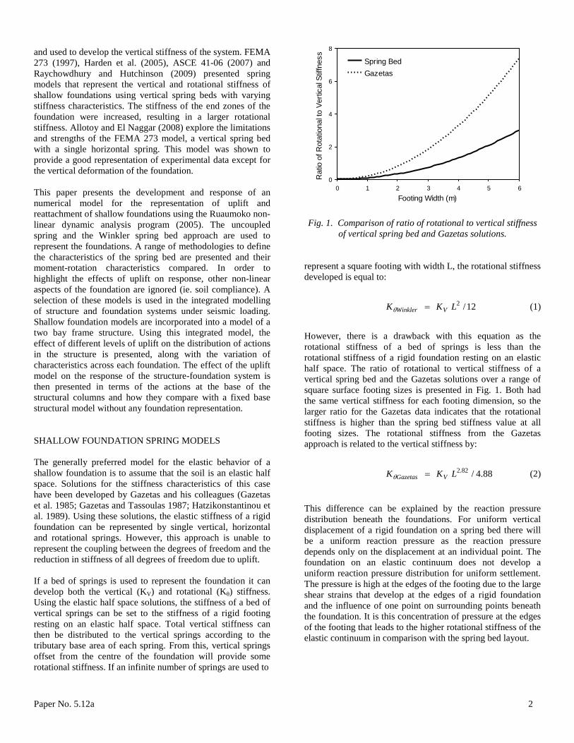
Fig. 1. Comparison of ratio of rotational to vertical stiffness
of vertical spring bed and Gazetas solutions. represent a square footing with width L, the rotational stiffness developed is equal to:
12/2LKK VWinkler =θ (1)
However, there is a drawback with this equation as the rotational stiffness of a bed of springs is less than the rotational stiffness of a rigid foundation resting on an elastic half space. The ratio of rotational to vertical stiffness of a vertical spring bed and the Gazetas solutions over a range of square surface footing sizes is presented in Fig. 1. Both had the same vertical stiffness for each footing dimension, so the larger ratio for the Gazetas data indicates that the rotational stiffness is higher than the spring bed stiffness value at all footing sizes. The rotational stiffness from the Gazetas approach is related to the vertical stiffness by:
88.4/82.2LKK VGazetas =θ (2) This difference can be explained by the reaction pressure distribution beneath the foundations. For uniform vertical displacement of a rigid foundation on a spring bed there will be a uniform reaction pressure as the reaction pressure depends only on the displacement at an individual point. The foundation on an elastic continuum does not develop a uniform reaction pressure distribution for uniform settlement. The pressure is high at the edges of the footing due to the large shear strains that develop at the edges of a rigid foundation and the influence of one point on surrounding points beneath the foundation. It is this concentration of pressure at the edges of the footing that leads to the higher rotational stiffness of the elastic continuum in comparison with the spring bed layout.
Paper No. 5.12a 3
Compound Element Spring Bed Model
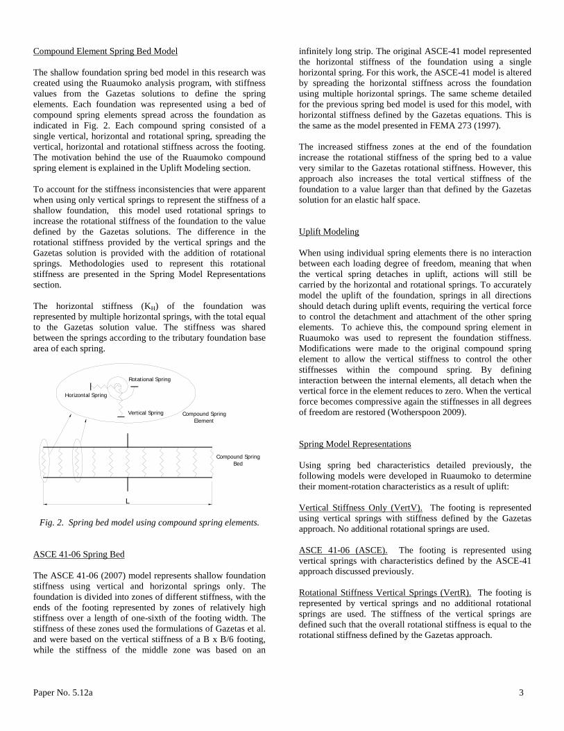
The shallow foundation spring bed model in this research was created using the Ruaumoko analysis program, with stiffness values from the Gazetas solutions to define the spring elements. Each foundation was represented using a bed of compound spring elements spread across the foundation as indicated in Fig. 2. Each compound spring consisted of a single vertical, horizontal and rotational spring, spreading the vertical, horizontal and rotational stiffness across the footing. The motivation behind the use of the Ruaumoko compound spring element is explained in the Uplift Modeling section. To account for the stiffness inconsistencies that were apparent when using only vertical springs to represent the stiffness of a shallow foundation, this model used rotational springs to increase the rotational stiffness of the foundation to the value defined by the Gazetas solutions. The difference in the rotational stiffness provided by the vertical springs and the Gazetas solution is provided with the addition of rotational springs. Methodologies used to represent this rotational stiffness are presented in the Spring Model Representations section. The horizontal stiffness (KH) of the foundation was represented by multiple horizontal springs, with the total equal to the Gazetas solution value. The stiffness was shared between the springs according to the tributary foundation base area of each spring.
L
Horizontal Spring
Rotational Spring
Compound SpringBed
Vertical Spring Compound SpringElement
Fig. 2. Spring bed model using compound spring elements.
ASCE 41-06 Spring Bed
The ASCE 41-06 (2007) model represents shallow foundation stiffness using vertical and horizontal springs only. The foundation is divided into zones of different stiffness, with the ends of the footing represented by zones of relatively high stiffness over a length of one-sixth of the footing width. The stiffness of these zones used the formulations of Gazetas et al. and were based on the vertical stiffness of a B x B/6 footing, while the stiffness of the middle zone was based on an
infinitely long strip. The original ASCE-41 model represented the horizontal stiffness of the foundation using a single horizontal spring. For this work, the ASCE-41 model is altered by spreading the horizontal stiffness across the foundation using multiple horizontal springs. The same scheme detailed for the previous spring bed model is used for this model, with horizontal stiffness defined by the Gazetas equations. This is the same as the model presented in FEMA 273 (1997). The increased stiffness zones at the end of the foundation increase the rotational stiffness of the spring bed to a value very similar to the Gazetas rotational stiffness. However, this approach also increases the total vertical stiffness of the foundation to a value larger than that defined by the Gazetas solution for an elastic half space.
Uplift Modeling
When using individual spring elements there is no interaction between each loading degree of freedom, meaning that when the vertical spring detaches in uplift, actions will still be carried by the horizontal and rotational springs. To accurately model the uplift of the foundation, springs in all directions should detach during uplift events, requiring the vertical force to control the detachment and attachment of the other spring elements. To achieve this, the compound spring element in Ruaumoko was used to represent the foundation stiffness. Modifications were made to the original compound spring element to allow the vertical stiffness to control the other stiffnesses within the compound spring. By defining interaction between the internal elements, all detach when the vertical force in the element reduces to zero. When the vertical force becomes compressive again the stiffnesses in all degrees of freedom are restored (Wotherspoon 2009).
Spring Model Representations
Using spring bed characteristics detailed previously, the following models were developed in Ruaumoko to determine their moment-rotation characteristics as a result of uplift: Vertical Stiffness Only (VertV).
The footing is represented using vertical springs with stiffness defined by the Gazetas approach. No additional rotational springs are used.
ASCE 41-06 (ASCE).
The footing is represented using vertical springs with characteristics defined by the ASCE-41 approach discussed previously.
Rotational Stiffness Vertical Springs (VertR).
The footing is represented by vertical springs and no additional rotational springs are used. The stiffness of the vertical springs are defined such that the overall rotational stiffness is equal to the rotational stiffness defined by the Gazetas approach.

Paper No. 5.12a 4
Vertical and Rotational Stiffness (V&R).
The footing is represented by vertical and rotational springs such that both the Gazetas vertical and rotational stiffness is developed by the model. As the vertical springs provide some level of rotational stiffness, the additional rotational stiffness (Kθr) required is equal to:
12/2LKKK Vr −= θθ (3)
This additional rotational stiffness is distributed evenly to the springs across the footing according to their tributary area of foundation base. V&R Progressive (Prog).
The footing in this model is similar to the V&R model above, but instead of distributing the rotational stiffness evenly across the footing, the stiffness reduces using the area of footing remaining in contact with the soil and the Gazetas rotational stiffness for that area.
Three Spring (3Spr).
This is a simplified model, with a single spring used to represent the stiffness in each degree of freedom. Total stiffness characteristics are the same as the V&R model. As there is only a single vertical spring uplift is either 100% or 0%, with no gradual transition.
Spring Discretization
A number of spring discretization schemes were investigated to determine the effect on the moment-rotation response of the Ruaumoko shallow foundation model with uplift. A 4.0 m square surface foundation resting on clay with a shear modulus of 17 MPa was used to test the response of the V&R spring model described above. The number of springs used for this model ranged from 5 to 101, and Fig. 3 presents the moment rotation characteristics of each. Results indicate the large stepped nature of the moment-rotation response of models with a smaller number of springs, as the detachment of each spring represented a large reduction in the area of foundation in contact with the ground below. This stepped nature reduces with an increased number of springs, and the results of the 41 and 101 spring models show only small differences in response. As any further increase in the number of springs showed no discernable improvement in the moment-rotation response, for the remainder of this paper the 101 spring model is used.
Moment Rotation Response
Using a spring bed with 101 elements, the moment-rotation characteristics of each of the spring bed representations were analyzed for the same 4.0 m square surface foundation. Moment-rotation characteristics are presented in Fig. 4 up to the point of detachment of half of the foundation. The points
plotted on the moment-rotation curve represent different levels of footing uplift. The first point identifies when the edge of the footing detaches, with the following representing uplift fractions of 1/8, ¼, 3/8 and ½ the footing length.
0 0.01 0.02 0.03 0.040
0.5
1
1.5
2
2.5x 10
4
Rotation (rads)
Mom
ent (
kNm
)
Onset of Uplif t
5112141101
Fig. 3. Effect of spring discretization on the moment-rotation
response of the shallow foundation model with uplift.
0 0.01 0.02 0.03 0.04 0.050
1
2
3x 10
4
Rotation (rads)
Mom
ent (
kNm
)
Prog
V&R
ASCE
VertRVertV
Fig. 4. Moment-rotation response of shallow foundation
spring models. The moment-rotation response of the VertV model emphasizes the inability of vertical springs to represent both rotational and vertical foundations presented in Fig. 4. There is a significant reduction in the moment capacity at each rotation level. Apart from the VertV model, the rotational stiffness of the foundation is accurately represented at low moments. However, once uplift is initiated a range of moment-rotation characteristics are apparent.

Paper No. 5.12a 5
The increase in the vertical stiffness of the ASCE and VertR spring models compared to the Gazetas solution results in a reduction in the static settlement of the foundation. Because of this, both these models develop uplift of half the footing much earlier than the other models considered. As the static settlement of the VertR model is approximately half that of the ASCE model, it experiences the most rapid uplift progression. The uplift fractions of the three models with the same vertical stiffness (Prog, V&R, VertV) occur at almost identical rotations. The models with larger rotational stiffness require larger moments to reach these rotations, but as the vertical settlement is the same for all models, the same rotation is required to develop each fraction of footing uplift. Although the Prog model represents the most likely response of the footing on an elastic material, its major weakness is that it can only be used to model monotonic loading. This is because the reduction in stiffness of a footing due to uplift of a certain length will be less than the stiffness of an individual footing of the same length. For example, the reduction in stiffness when half the footing has detached from the ground is only 34% of the stiffness when the entire foundation is in contact with the ground. If spring stiffnesses were set using this methodology, loading in one direction would be stiffer that the other once uplift was initiated. For this reason this stiffness model is not suitable for cyclic loading of a spring bed.
0 0.01 0.02 0.03 0.04 0.050
1
2
3x 10
4
Rotation (rads)
Mom
ent (
kNm
)
V&RASCEVertR
Fig. 5. Moment-rotation response of shallow foundation
spring models with settlement modification. If the static settlement of all methodologies is set to the value defined by the vertical stiffness from the Gazetas solution, the effect on the moment-rotation response of the altered vertical stiffness models is shown in Fig 5. The ASCE model develops an increased moment capacity, but this still levels off rapidly along with the fraction of uplift. The increased settlement shifted the onset of uplift to the same point as the other
models, but as the vertical stiffness was larger at the edges the rate of uplift with rotation was larger. With the increase in static settlement, the VertR model developed a moment rotation response very similar to the V&R model, with fractions of uplift occurring at almost identical rotations. While not shown in the figure, beyond uplift of half the footing the VertR model reduces more rapidly than the V&R model. This is indicated in Fig. 5 by the flattening out of the moment-rotation response. INTEGRATED STRUCTURE FOUNDATION MODELLING In order to compare the dynamic characteristics of the shallow foundation models, a two-dimensional two bay frame structure was developed and shallow foundations were attached to the base of each column. The only non-linear characteristic included in these analyses was uplift modelling.
Properties of the frame structure are summarised in Fig. 6, with each bay 7.0 m wide and four floors 3.65 m in height. The frame was constructed of 35 MPa concrete, with columns 1000 mm square and beams 500 x 900 mm. To account for the effect of cracking on member stiffness, effective moments of inertia (Ieff) of the member sections were calculated using modifications to the gross moment of inertia (Ig) defined by NZS 3101:2006 (SNZ 2006). The structure was supported by surface foundations beneath each of the columns. Each was 4.0 m square, and was sized using the static vertical loads on the central column for a static bearing capacity factor of safety of 3. Soil characteristics were based on the assumption of a 17 MPa shear modulus and a Poisson’s ratio of 0.5.
7.0 m
4 st
orey
s @
3.6
5 m
4.0 m
4.0
m
Fig. 6. Structural frame and foundation plan.
Structural Model
As the structure was assumed to remain elastic during loading, the structural elements were modeled using elastic beam and beam column elements in Ruaumoko. Each floor was modeled as a rigid diaphragm with the total horizontal mass of each floor lumped at each level. To ensure that each column was subjected to the desired axial force, the vertical mass at each
Paper No. 5.12a 6
floor level was applied at the column nodes and calculated based on the tributary area of floor space of each node. Elastic structural viscous damping was modeled by defining appropriate Rayleigh damping coefficients to the structure to provide 5% viscous damping to the fundamental mode, and at least 3% to every other mode (Carr 2005). Ruaumoko material specific Rayleigh damping coefficients were used to apply damping characteristics only to the structure and pile elements. Soil damping characteristics were modeled using dashpots explained in the following section. Stiffness proportional damping parameters were applied to the structural elements, while mass proportional damping parameters were applied to the nodes due to the use of lumped masses. No stiffness proportional damping parameters were used for the soil spring elements, as it would have resulted in an over-representation of the damping of the soil.
Foundation Model
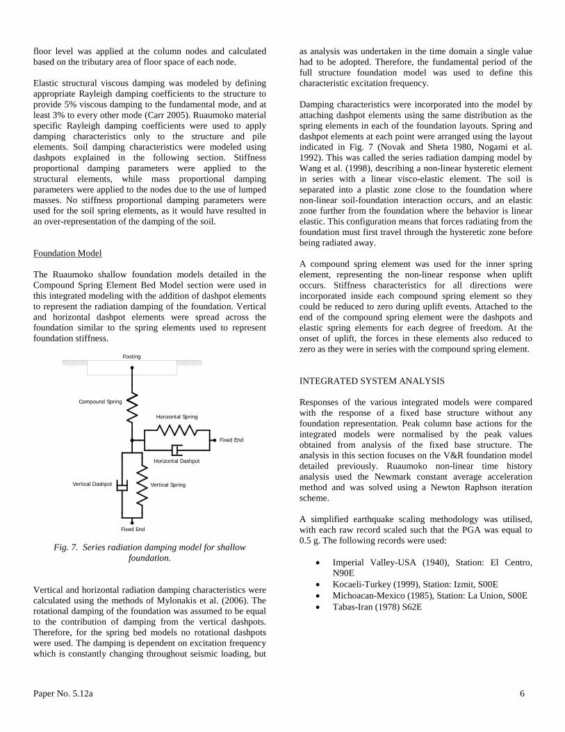
The Ruaumoko shallow foundation models detailed in the Compound Spring Element Bed Model section were used in this integrated modeling with the addition of dashpot elements to represent the radiation damping of the foundation. Vertical and horizontal dashpot elements were spread across the foundation similar to the spring elements used to represent foundation stiffness.
Compound Spring
Fixed End
Fixed End
Horizontal Spring
Horizontal Dashpot
Vertical Dashpot Vertical Spring
Footing
Fig. 7. Series radiation damping model for shallow
foundation. Vertical and horizontal radiation damping characteristics were calculated using the methods of Mylonakis et al. (2006). The rotational damping of the foundation was assumed to be equal to the contribution of damping from the vertical dashpots. Therefore, for the spring bed models no rotational dashpots were used. The damping is dependent on excitation frequency which is constantly changing throughout seismic loading, but
as analysis was undertaken in the time domain a single value had to be adopted. Therefore, the fundamental period of the full structure foundation model was used to define this characteristic excitation frequency. Damping characteristics were incorporated into the model by attaching dashpot elements using the same distribution as the spring elements in each of the foundation layouts. Spring and dashpot elements at each point were arranged using the layout indicated in Fig. 7 (Novak and Sheta 1980, Nogami et al. 1992). This was called the series radiation damping model by Wang et al. (1998), describing a non-linear hysteretic element in series with a linear visco-elastic element. The soil is separated into a plastic zone close to the foundation where non-linear soil-foundation interaction occurs, and an elastic zone further from the foundation where the behavior is linear elastic. This configuration means that forces radiating from the foundation must first travel through the hysteretic zone before being radiated away. A compound spring element was used for the inner spring element, representing the non-linear response when uplift occurs. Stiffness characteristics for all directions were incorporated inside each compound spring element so they could be reduced to zero during uplift events. Attached to the end of the compound spring element were the dashpots and elastic spring elements for each degree of freedom. At the onset of uplift, the forces in these elements also reduced to zero as they were in series with the compound spring element. INTEGRATED SYSTEM ANALYSIS Responses of the various integrated models were compared with the response of a fixed base structure without any foundation representation. Peak column base actions for the integrated models were normalised by the peak values obtained from analysis of the fixed base structure. The analysis in this section focuses on the V&R foundation model detailed previously. Ruaumoko non-linear time history analysis used the Newmark constant average acceleration method and was solved using a Newton Raphson iteration scheme. A simplified earthquake scaling methodology was utilised, with each raw record scaled such that the PGA was equal to 0.5 g. The following records were used:
• Imperial Valley-USA (1940), Station: El Centro, N90E
• Kocaeli-Turkey (1999), Station: Izmit, S00E • Michoacan-Mexico (1985), Station: La Union, S00E • Tabas-Iran (1978) S62E
Paper No. 5.12a 7
Table 1. Fundamental period and damping characteristics of foundation models used in integrated analysis
Foundation Model Fundamental
Period (secs) Damping (%)
Fixed base 0.475 5.0 V&R 0.552 6.9 ASCE 0.552 7.6 VertV 0.590 8.2
The fundamental period and damping of each integrated model presented in Table 1 was determined using a free vibration analysis. Elastic viscous damping of the structure and the radiation damping of the footings contribute to this value. The V&R model and the ASCE model have the same fundamental period as the footings of each model have identical rotational and horizontal stiffness. The VertV model footings have much smaller rotational stiffness, resulting in a lengthening of the period of the integrated model.
Time History Response
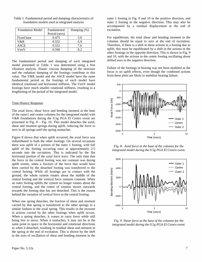
The axial force, shear force and bending moment at the base of the outer1 and centre columns for the integrated model with V&R foundations during the 0.5g PGA El Centro event are presented in Fig. 8 – Fig. 10. This model detaches the axial, shear and moment springs during uplift, reducing the force to zero in all springs until the spring reattaches. Figure 8 shows that when uplift occurred, the axial force was redistributed to both the other footings. On several occasions there was uplift of a portion of the outer 1 footing, with full uplift of the footing occurring once at approximately 2.5 seconds into the excitation. This is indicated by the flat horizontal portion of the axial force trace. The only time that the force in the central footing was not constant was during uplift events, when a fraction of the force that would have been carried by the detached footing was transferred to the central footing. While all footings are in contact with the ground, the whole system rotates about the middle of the central footing and the vertical force remains constant. When an outer footing uplifts the system no longer rotates about the central footing, and the centre of rotation moves outwards towards the footing that has not detached. This is the reason behind the variation of vertical force in the central footing. When one spring detaches, the fraction of shear and moment carried by that spring is transferred to the other springs in a similar fashion to the axial spring. This results in the increase in actions carried by the other footings when uplift occurs. When a spring detaches, it ceases to carry force while still being free to move. When it reattaches, it may not be at the same point in space in the horizontal and rotational directions as when it detached, resulting in residual shear and moment in the spring at the end of excitation. This is shown by the shift in the axes of oscillation of shear and bending moment in the
outer 1 footing in Fig. 9 and 10 in the positive direction, and outer 2 footing in the negative direction. This may also be accompanied by a residual displacement at the end of excitation. For equilibrium, the total shear and bending moment in the columns should be equal to zero at the end of excitation. Therefore, if there is a shift in these actions in a footing due to uplift, this must be equilibrated by a shift in the actions in the other footings in the opposite direction. This is shown in Fig. 9 and 10, with the actions in the centre footing oscillating about shifted axes in the negative direction. Failure of the footings in bearing was not been modeled as the focus is on uplift effects, even though the combined actions from these plots are likely to mobilize bearing failure.
0 5 10-3000
-2500
-2000
-1500
-1000
-500
0
500
Time (secs)
Axia
l For
ce (k
N)
Outer 1CentreOuter 2
Fig. 8. Axial force at the base of the columns for the
integrated model during the 0.5g PGA El Centro event.
0 5 10-4000
-2000
0
2000
4000
6000
Time (secs)
Bend
ing
Mom
ent (
kNm
)
Outer 1CentreOuter 2
Fig. 9. Shear force at the base of the columns for the
integrated model during the 0.5g PGA El Centro event.

Paper No. 5.12a 8
0 5 10-2000
-1000
0
1000
2000
Time (secs)
Shea
r (kN
)
Outer 1CentreOuter 2
Fig. 10. Bending moment at the base of the columns for the
integrated model during the 0.5g PGA El Centro event.
0 1 2 3 4 5-0.016
-0.008
0
0.008
0.016
0.024
0.032
0.04
Time (secs)
Verti
cal D
ispl
acem
ent (
m)
Edge 1CentreEdge 2
Fig. 11. Vertical displacement across the outer 1 footing
during the 0.5g PGA El Centro earthquake record.
0 1 2 3 4 5-0.012
-0.008
-0.004
0
0.004
0.008
0.012
Time (secs)
Verti
cal D
ispl
acem
ent (
m)
Edge 1CentreEdge 2
Fig. 12. Vertical displacement across the central footing
during the 0.5g PGA El Centro earthquake record.
The three traces in Fig. 11 are the vertical displacement of the centre and two edges of the left footing. The edge foundation spring that is on the exterior side (Edge 1) of the footing had the largest variation in vertical displacement, followed by the central spring. The edge spring that was on the internal side of the footing (Edge 2) had a much smaller variation in vertical displacement, indicating that prior to uplift the footing was pivoting about this internal edge. During uplift all points of the footing move upwards and the whole footing detaches from the ground. At this point the rotation and horizontal displacement are controlled by the stiffness of the structure and the footing still in contact with the ground. Similar traces for the central footing are shown in Fig. 12. Prior to uplift the centre of the footing shows no movement which is consistent with the observation that the vertical force does not change. The vertical displacements of the edges are out of phase with each other and indicate the rotational response of the footing due the applied moment. During the uplift of the outer footings, the central footing does not rotate about its centre and a fraction of the footing detaches from the ground. An example of this occurs at 2.2 seconds, where more than half the centre footing detaches from the ground.
Effect of uplift on non-vertical degrees of freedom
The use of vertical force to control the detachment of horizontal and rotational springs during uplift influences the force-displacement characteristics. Because of the use of springs and the way uplift is modeled there will be residual displacement in the horizontal and rotational springs at the end of excitation if the detachment and reattachment displacement and rotation points are not identical. Even if forces in the spring elements remain elastic in the compressive range, there may still be residual forces in the springs because of uplift. The events that occur during uplift modeling are detailed below and portrayed in Fig. 13 for horizontal displacement.
• Prior to uplift the forces in the footing horizontal spring are determined by the displacement from the origin, defined by the static horizontal position of the footing.
• During uplift there is no force in all springs representing the footing stiffness
• At the point of reattachment of the springs, the force in the springs is zero and the displacement at this point becomes the new origin from which force-displacement characteristics are determined. In a global sense there is horizontal displacement, however the horizontal spring force-displacement characteristics begins at a new origin.
• After reattachment, the force in the horizontal spring is determined by the displacement from the new origin at the point of reattachment. At the end of

Paper No. 5.12a 9
excitation there will be a residual force if the final position is not equal to the reattached point.
Displacement from origin
Origin
New Origin
New Origin
Displacement from new origin
Displacement from origin
Origin
a) b)
c) d)
Fig. 13. Characteristics of portal frame model with shallow
foundations a) before uplift; b) during uplift; c) at reattachment; d) after reattachment.
Another informative representation of the uplift modeling is provided by force-displacement or hysteretic characteristics of the shear and moment springs. For this model the shear and moment have been defined by elastic springs, however these are still controlled by the release of stiffness when vertical force reduces to zero. To determine the characteristics of these springs, the shear-horizontal displacement response of the right horizontal spring is presented in Fig. 14. The characteristics of the rotational spring are similar to the horizontal spring so have not been shown here. The response of a shallow foundation using a 3Spr and a V&R model is presented in this figure. The 3Spr model is either attached or fully detached, which provides a simplified representation of the processing occurring in the V&R model with its gradual progression towards complete uplift of the foundation. The response of the two models are similar prior to any uplift, with both following the elastic slope a-a. However once uplift is initiated the two diverge, with the V&R model developing a gradual reduction in stiffness compared to the sharp reduction in the stiffness of the 3Spr model to zero.
-5 -2.5 0 2.5 5
x 10-3
-1000
-500
0
500
1000
Horizontal Displacement (m)
Shea
r (kN
)
0
a
a b
c c
d
d
e
e
f
3 SprV&R
Fig. 14. Shear-horizontal displacement of right footing of
frame. To simplify the explanation the processes occurring during hysteresis the 3Spr model is used, with labels identifying each characteristics step in Fig. 14. The overall process can be defined as follows:
• Prior to excitation, there is no shear force applied to the footing, resulting in zero horizontal displacement. This is defined by point 0.
• Prior to uplift points follow the elastic slope a-a, where force and displacement are calculated using point 0 as the origin.
• At point b, the vertical force reduces to zero, forcing the horizontal spring to detach. During the next time step the shear force reduces to zero while the horizontal movement increases due to zero stiffness.
• During uplift, there is movement along line c-c and the spring carries no shear force.
• Once vertical force becomes compressive again, the springs reattach. The point of reattachment is defined by the line d-d, which becomes the new origin from which force-displacement characteristics are defined. This is the point defined in Figure 13c.
• Force-displacement characteristics then follow the line e-e, which has the same elastic slope as line a-a. Points will follow this line until there is another uplift event.
At the end of excitation the force-displacement characteristics are defined by point f. This explains the force in the spring at the end of excitation, as well as the displacement at the end of excitation. If the point of detachment and the point of reattachment of the horizontal spring were at the same position, then there would be no residual force. The V&R model follows similar steps, but with a smoother transition due to the gradual detachment and attachment of the spring bed.
Paper No. 5.12a 10
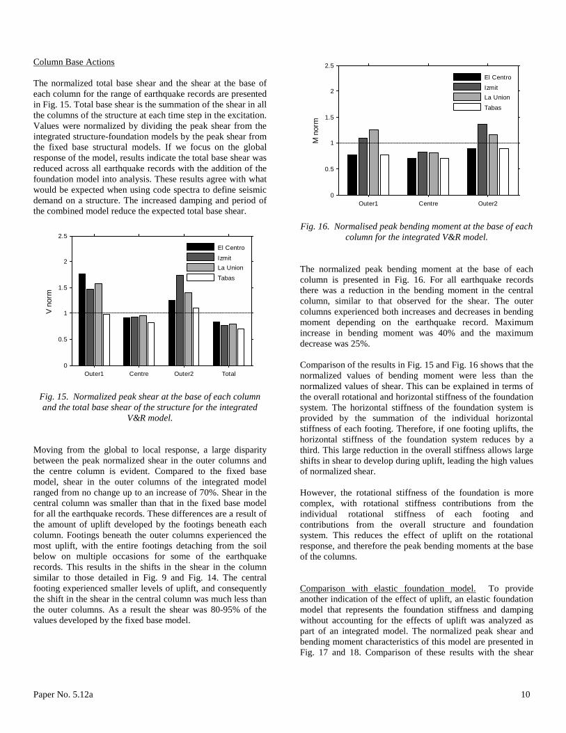
Column Base Actions
The normalized total base shear and the shear at the base of each column for the range of earthquake records are presented in Fig. 15. Total base shear is the summation of the shear in all the columns of the structure at each time step in the excitation. Values were normalized by dividing the peak shear from the integrated structure-foundation models by the peak shear from the fixed base structural models. If we focus on the global response of the model, results indicate the total base shear was reduced across all earthquake records with the addition of the foundation model into analysis. These results agree with what would be expected when using code spectra to define seismic demand on a structure. The increased damping and period of the combined model reduce the expected total base shear.
Outer1 Centre Outer2 Total0
0.5
1
1.5
2
2.5
V no
rm
El Centro
IzmitLa Union
Tabas
Fig. 15. Normalized peak shear at the base of each column and the total base shear of the structure for the integrated
V&R model. Moving from the global to local response, a large disparity between the peak normalized shear in the outer columns and the centre column is evident. Compared to the fixed base model, shear in the outer columns of the integrated model ranged from no change up to an increase of 70%. Shear in the central column was smaller than that in the fixed base model for all the earthquake records. These differences are a result of the amount of uplift developed by the footings beneath each column. Footings beneath the outer columns experienced the most uplift, with the entire footings detaching from the soil below on multiple occasions for some of the earthquake records. This results in the shifts in the shear in the column similar to those detailed in Fig. 9 and Fig. 14. The central footing experienced smaller levels of uplift, and consequently the shift in the shear in the central column was much less than the outer columns. As a result the shear was 80-95% of the values developed by the fixed base model.
Outer1 Centre Outer20
0.5
1
1.5
2
2.5
M n
orm
El Centro
IzmitLa Union
Tabas
Fig. 16. Normalised peak bending moment at the base of each
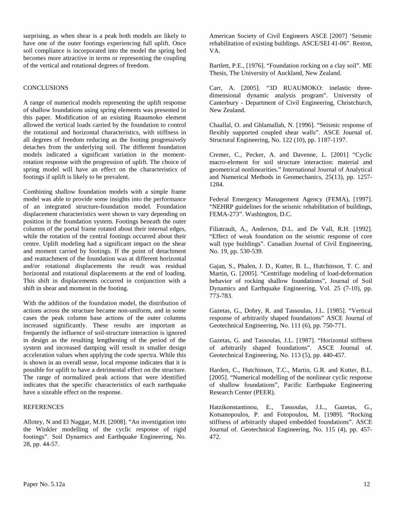
column for the integrated V&R model. The normalized peak bending moment at the base of each column is presented in Fig. 16. For all earthquake records there was a reduction in the bending moment in the central column, similar to that observed for the shear. The outer columns experienced both increases and decreases in bending moment depending on the earthquake record. Maximum increase in bending moment was 40% and the maximum decrease was 25%. Comparison of the results in Fig. 15 and Fig. 16 shows that the normalized values of bending moment were less than the normalized values of shear. This can be explained in terms of the overall rotational and horizontal stiffness of the foundation system. The horizontal stiffness of the foundation system is provided by the summation of the individual horizontal stiffness of each footing. Therefore, if one footing uplifts, the horizontal stiffness of the foundation system reduces by a third. This large reduction in the overall stiffness allows large shifts in shear to develop during uplift, leading the high values of normalized shear. However, the rotational stiffness of the foundation is more complex, with rotational stiffness contributions from the individual rotational stiffness of each footing and contributions from the overall structure and foundation system. This reduces the effect of uplift on the rotational response, and therefore the peak bending moments at the base of the columns. Comparison with elastic foundation model. To provide another indication of the effect of uplift, an elastic foundation model that represents the foundation stiffness and damping without accounting for the effects of uplift was analyzed as part of an integrated model. The normalized peak shear and bending moment characteristics of this model are presented in Fig. 17 and 18. Comparison of these results with the shear
Paper No. 5.12a 11
characteristics in Fig. 15 shows that the elastic foundation model developed much more consistent characteristics across each column and for the system as a whole. This is not surprising given that each foundation had the same stiffness and damping characteristics. For each earthquake record the normalized shear values for each column were almost identical, with a maximum increase in shear of 20% and a maximum decrease of 25%. Because the shear was equalized across the foundation system, the actions at the base of the outer columns were less than the integrated V&R model. However, the peak total base shear was larger in the model with elastic foundations. With an elastic foundation model, the fundamental period of the integrated model will remain constant throughout the excitation. With uplift modeling incorporated, there will be lengthening of the fundamental period of the integrated model during periods of uplift. For the earthquake records used in this study, this shifted the period of the structure during large accelerations and reduced the seismic demands on the integrated model.
Outer1 Centre Outer2 Total0
0.5
1
1.5
2
2.5
V no
rm
El Centro
IzmitLa Union
Tabas
Fig. 17. Normalized peak shear at the base of each column and the total base shear of the structure for the integrated
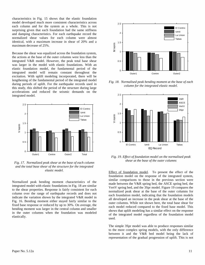
elastic model. Normalized peak bending moment characteristics of the integrated model with elastic foundations in Fig. 18 are similar to the shear properties. Response is fairly consistent for each column over the range of earthquake records and does not indicate the variation shown by the integrated V&R model in Fig. 16. Bending moment either stayed fairly similar to the fixed base response or reduced by up to 30%. On average, the bending moment was larger in the central column and smaller in the outer columns when the foundation was modeled elastically.
Outer1 Centre Outer20
0.5
1
1.5
2
2.5
M n
orm
El Centro
IzmitLa Union
Tabas
Fig. 18. Normalised peak bending moment at the base of each
column for the integrated elastic model.
El Centro Izmit La Union Tabas0
0.5
1
1.5
2
2.5
EQ Record
V no
rm
V&R
ASCEVertV
3Spr
Fig. 19. Effect of foundation model on the normalised peak
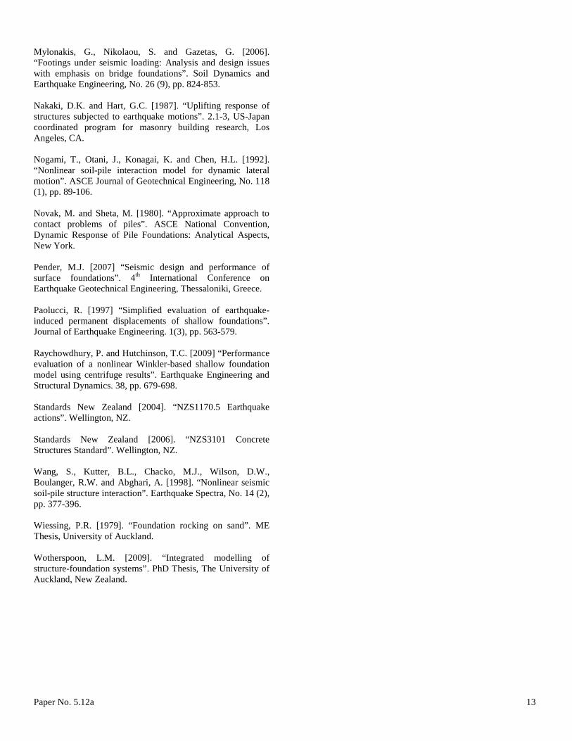
shear at the base of the outer columns Effect of foundation model
. To present the effect of the foundation model on the response of the integrated system, similar comparisons to those in the previous section were made between the V&R spring bed, the ASCE spring bed, the VertV spring bed, and the 3Spr model. Figure 19 compares the normalized peak shear at the base of the outer columns for each foundation model, indicating that the foundation models all developed an increase in the peak shear at the base of the outer columns. While not shown here, the total base shear for each model reduced compared to the fixed base model. This shows that uplift modeling has a similar effect on the response of the integrated model regardless of the foundation model used.
The simple 3Spr model was able to produce responses similar to the more complex spring models, with the only difference between it and the V&R bed model being the lack of representation of the gradual progression of uplift. This is not
Paper No. 5.12a 12
surprising, as when shear is a peak both models are likely to have one of the outer footings experiencing full uplift. Once soil compliance is incorporated into the model the spring bed becomes more attractive in terms or representing the coupling of the vertical and rotational degrees of freedom. CONCLUSIONS A range of numerical models representing the uplift response of shallow foundations using spring elements was presented in this paper. Modification of an existing Ruaumoko element allowed the vertical loads carried by the foundation to control the rotational and horizontal characteristics, with stiffness in all degrees of freedom reducing as the footing progressively detaches from the underlying soil. The different foundation models indicated a significant variation in the moment-rotation response with the progression of uplift. The choice of spring model will have an effect on the characteristics of footings if uplift is likely to be prevalent. Combining shallow foundation models with a simple frame model was able to provide some insights into the performance of an integrated structure-foundation model. Foundation displacement characteristics were shown to vary depending on position in the foundation system. Footings beneath the outer columns of the portal frame rotated about their internal edges, while the rotation of the central footings occurred about their centre. Uplift modeling had a significant impact on the shear and moment carried by footings. If the point of detachment and reattachment of the foundation was at different horizontal and/or rotational displacements the result was residual horizontal and rotational displacements at the end of loading. This shift in displacements occurred in conjunction with a shift in shear and moment in the footing. With the addition of the foundation model, the distribution of actions across the structure became non-uniform, and in some cases the peak column base actions of the outer columns increased significantly. These results are important as frequently the influence of soil-structure interaction is ignored in design as the resulting lengthening of the period of the system and increased damping will result in smaller design acceleration values when applying the code spectra. While this is shown in an overall sense, local response indicates that it is possible for uplift to have a detrimental effect on the structure. The range of normalized peak actions that were identified indicates that the specific characteristics of each earthquake have a sizeable effect on the response. REFERENCES Allotey, N and El Naggar, M.H. [2008]. “An investigation into the Winkler modelling of the cyclic response of rigid footings”. Soil Dynamics and Earthquake Engineering, No. 28, pp. 44-57.
American Society of Civil Engineers ASCE [2007] ‘Seismic rehabilitation of existing buildings. ASCE/SEI 41-06”. Reston, VA. Bartlett, P.E., [1976]. “Foundation rocking on a clay soil”. ME Thesis, The University of Auckland, New Zealand. Carr, A. [2005]. “3D RUAUMOKO: inelastic three-dimensional dynamic analysis program”. University of Canterbury - Department of Civil Engineering, Christchurch, New Zealand. Chaallal, O. and Ghlamallah, N. [1996]. “Seismic response of flexibly supported coupled shear walls”. ASCE Journal of. Structural Engineering, No. 122 (10), pp. 1187-1197. Cremer, C., Pecker, A. and Davenne, L. [2001] “Cyclic macro-element for soil structure interaction: material and geometrical nonlinearities.” International Journal of Analytical and Numerical Methods in Geomechanics, 25(13), pp. 1257-1284. Federal Emergency Management Agency (FEMA), [1997]. “NEHRP guidelines for the seismic rehabilitation of buildings, FEMA-273”. Washington, D.C. Filiatrault, A., Anderson, D.L. and De Vall, R.H. [1992]. “Effect of weak foundation on the seismic response of core wall type buildings”. Canadian Journal of Civil Engineering, No. 19, pp. 530-539. Gajan, S., Phalen, J. D., Kutter, B. L., Hutchinson, T. C. and Martin, G. [2005]. “Centrifuge modeling of load-deformation behavior of rocking shallow foundations”, Journal of Soil Dynamics and Earthquake Engineering, Vol. 25 (7-10), pp. 773-783. Gazetas, G., Dobry, R. and Tassoulas, J.L. [1985]. “Vertical response of arbitrarily shaped foundations” ASCE Journal of Geotechnical Engineering, No. 111 (6), pp. 750-771. Gazetas, G. and Tassoulas, J.L. [1987]. “Horizontal stiffness of arbitrarily shaped foundations”. ASCE Journal of. Geotechnical Engineering, No. 113 (5), pp. 440-457. Harden, C., Hutchinson, T.C., Martin, G.R. and Kutter, B.L. [2005]. “Numerical modelling of the nonlinear cyclic response of shallow foundations”, Pacific Earthquake Engineering Research Center (PEER). Hatzikonstantinou, E., Tassoulas, J.L., Gazetas, G., Kotsanopoulos, P. and Fotopoulou, M. [1989]. “Rocking stiffness of arbitrarily shaped embedded foundations”. ASCE Journal of. Geotechnical Engineering, No. 115 (4), pp. 457-472.
Paper No. 5.12a 13
Mylonakis, G., Nikolaou, S. and Gazetas, G. [2006]. “Footings under seismic loading: Analysis and design issues with emphasis on bridge foundations”. Soil Dynamics and Earthquake Engineering, No. 26 (9), pp. 824-853. Nakaki, D.K. and Hart, G.C. [1987]. “Uplifting response of structures subjected to earthquake motions”. 2.1-3, US-Japan coordinated program for masonry building research, Los Angeles, CA. Nogami, T., Otani, J., Konagai, K. and Chen, H.L. [1992]. “Nonlinear soil-pile interaction model for dynamic lateral motion”. ASCE Journal of Geotechnical Engineering, No. 118 (1), pp. 89-106. Novak, M. and Sheta, M. [1980]. “Approximate approach to contact problems of piles”. ASCE National Convention, Dynamic Response of Pile Foundations: Analytical Aspects, New York. Pender, M.J. [2007] “Seismic design and performance of surface foundations”. 4th International Conference on Earthquake Geotechnical Engineering, Thessaloniki, Greece. Paolucci, R. [1997] “Simplified evaluation of earthquake-induced permanent displacements of shallow foundations”. Journal of Earthquake Engineering. 1(3), pp. 563-579. Raychowdhury, P. and Hutchinson, T.C. [2009] “Performance evaluation of a nonlinear Winkler-based shallow foundation model using centrifuge results”. Earthquake Engineering and Structural Dynamics. 38, pp. 679-698. Standards New Zealand [2004]. “NZS1170.5 Earthquake actions”. Wellington, NZ. Standards New Zealand [2006]. “NZS3101 Concrete Structures Standard”. Wellington, NZ. Wang, S., Kutter, B.L., Chacko, M.J., Wilson, D.W., Boulanger, R.W. and Abghari, A. [1998]. “Nonlinear seismic soil-pile structure interaction”. Earthquake Spectra, No. 14 (2), pp. 377-396. Wiessing, P.R. [1979]. “Foundation rocking on sand”. ME Thesis, University of Auckland. Wotherspoon, L.M. [2009]. “Integrated modelling of structure-foundation systems”. PhD Thesis, The University of Auckland, New Zealand.