Embed Size (px)
Citation preview
1
EFFECT OF VERTICAL COMPONENT OF EARTHQUAKE ON THE
RESPONSE OF A FRICTION PENDULUM BEARING BASE
ISOLATION SYSTEM
Frederico AMARAL1 and Luís GUERREIRO
2
ABSTRACT
Friction Pendulum Bearings (FPB) are one of the most used base isolation systems worldwide, in
which the superstructure is isolated from the foundation through a sliding-based system. Ground
motions force structure to slide along the concave surface of the bearing under its own natural
frequency. This study aims to evaluate the influence of the vertical component of earthquake on FPB’s
response. The performance of FPB is numerically tested and analyzed for two distinct conditions: (i)
one test structure; and (ii) a real structure of a reinforced concrete lab with 3 floors. Seismic responses
of isolated structural systems are compared with and without considering the vertical component of
earthquake. The results showed that the vertical component of earthquake does not affect FPB’s
design: the maximum bearing displacement does not change with vertical component of earthquake.
Both lateral stiffness and friction resistance have instantaneous and random variations due to
oscillations of the vertical load on the support; however, the envelope of FPB’s response is not
significantly affected.
INTRODUCTION
Seismic isolation is an effective tool for earthquake resistant design of structures. Friction Pendulum
Bearing (FPB) is one type of base isolation system commonly used in practice, i.e. a structural joint
installed between the superstructure and its foundation, isolating the superstructure from severe
horizontal ground motions. It enhances the performance of structures well beyond the standard code
requirements with potential for substantial life-cycle cost reduction (e.g. minimizing interruption of
the use of the facility, reducing damaging deformation in structural and non-structural components).
(Eröz and DesRoches, 2008; Kravchuk et al, 2008; Mokha et al, 1996)
Seismic action is described by two horizontal and orthogonal components and one vertical
component. Contemporary engineering design professionals usually agree that it is primarily the
horizontal ground vibration motions of an earthquake that take damaging to a building. Furthermore,
structural details are designed mainly to support vertical loads with safety factors generally considered
sufficient to account for vertical seismic loads. (Zayas, 1987) Vertical earthquake motions, despite
neglected for earthquake resistant design of structures, could affect the response of some base isolation
devices such as FPB.
This paper discusses the main results and conclusions of the research project on “Effect of
vertical component of earthquake on the response of a Friction Pendulum Bearing base isolation
system” (Amaral, 2013). The research tested the effect of vertical component of earthquake on the
1 MSc in Civil Engineering, Instituto Superior Técnico, Lisbon, Portugal, [email protected]
2 Associate Professor, Instituto Superior Técnico, Lisbon, Portugal, [email protected]
2
FPB’s response. In this study two different structures were analysed – a test structure and a real
structure of a reinforced concrete 3-storey building.
FRICTION PENDULUM BEARING (FPB)
FPB has become a widely accepted device for seismic isolation of structures since the invention of
FPS® in 1985 by Victor Zayas, attested by numerous applications in very distinct conditions (Marioni,
2010). Nowadays, FPB is a seismic base isolation system in direct competition with other well-known
bearings (e.g. HDRB and LRB).
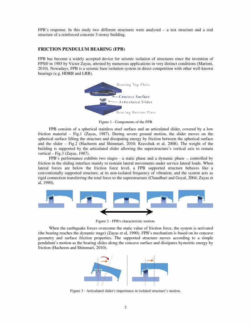
Figure 1 - Components of the FPB
FPB consists of a spherical stainless steel surface and an articulated slider, covered by a low
friction material – Fig.1 (Zayas, 1987). During severe ground motion, the slider moves on the
spherical surface lifting the structure and dissipating energy by friction between the spherical surface
and the slider – Fig.2 (Hacheem and Shimmari, 2010; Kravchuk et al, 2008). The weight of the
building is supported by the articulated slider allowing the superstructure’s vertical axis to remain
vertical – Fig.3 (Zayas, 1987).
FPB’s performance exhibits two stages - a static phase and a dynamic phase -, controlled by
friction in the sliding interface mainly to restrain lateral movements under service lateral loads. When
lateral forces are below the friction force level, a FPB supported structure behaves like a
conventionally supported structure, at its non-isolated frequency of vibration, and the system acts as
rigid connection transferring the total force to the superstructure (Chaudhari and Goyal, 2004; Zayas et
al, 1990).
Figure 2 - FPB's characteristic motion.
When the earthquake forces overcome the static value of friction force, the system is activated
(the bearing reaches the dynamic stage) (Zayas et al, 1990). FPB’s mechanism is based on its concave
geometry and surface friction properties. The supported structure moves according to a simple
pendulum’s motion as the bearing slides along the concave surface and dissipates hysteretic energy by
friction (Hacheem and Shimmari, 2010).
Figure 3 - Articulated slider's importance in isolated structure’s motion.
F. Amaral and L. Guerreiro 3
The frequency of the FPB is selected simply by choosing the radius of curvature of the concave
surface (R). It is independent of the mass of the supported structure (e.g. storage facilities or tanks). In
the Eq. 1, aV is the vertical absolute acceleration. Unless changes in vertical acceleration occur
(induced by structural dynamic motion or ground motions), aV is considered equal to the acceleration
of gravity (g).
R
af V
π2
1= (1)
The FPB lateral force has two components, (i) a restoring force due to the raising of the building
mass along the sliding surface, and (ii) a friction force due to friction at the sliding surface (Symans,
2013). The horizontal force, F, at the horizontal displacement u, can be expressed by the following
equation:
( ) frictionrestoringdyn FFusngWuR
WF +=××+×= &µ (2)
where W is the vertical load, µdyn is the dynamic friction coefficient of the sliding surface, and
sgn(ů) is the sign of the velocity used to define the direction of the friction force. The maximum lateral
force transmitted to the superstructure is reached for maximum displacement of the bearing.
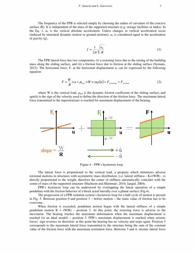
Figure 4 - FPB’s hysteresis loop.
The lateral force is proportional to the vertical load, a property which minimizes adverse
torsional motions in structures with asymmetric mass distribution. (i.e. lateral stiffness - K=(W/R) - is
directly proportional to the weight, therefore the center of stiffness automatically coincides with the
centre of mass of the supported structure (Hacheem and Shimmari, 2010; Jangid, 2004).
FPB’s hysteresis loop can be understood by overlapping the linear operation of a simple
pendulum with the friction behavior of a block acted laterally over a planar surface (Fig.4).
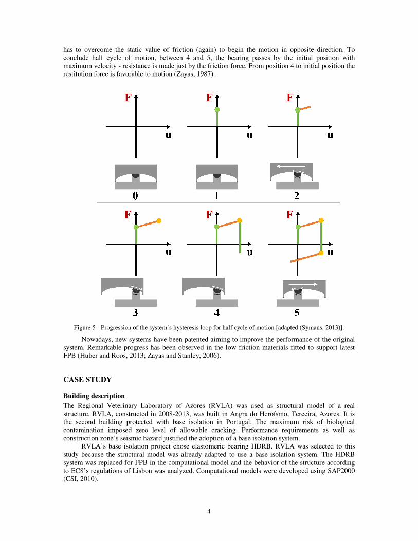
The progression of a FPB isolation system’s hysteresis loop for a half cycle of motion is present
in Fig. 5. Between position 0 and position 1 – before motion – the static value of friction has to be
overcome.
When friction is exceeded, pendulum motion began with the lateral stiffness of a simple
pendulum motion K = (W/R) – position 2. At this point, the restoring force is adverse to the
movement. The bearing reaches the maximum deformation when the maximum displacement is
reached (in an ideal model) – position 3. FPB’s maximum displacement is reached when seismic
forces’ sign reverses its direction: at this point the bearing has no velocity and stops again. Position 3
corresponds to the maximum lateral force transmitted to the structure being the sum of the constant
value of the friction force with the maximum restitution force. Between 3 and 4, seismic lateral force
4
has to overcome the static value of friction (again) to begin the motion in opposite direction. To
conclude half cycle of motion, between 4 and 5, the bearing passes by the initial position with
maximum velocity - resistance is made just by the friction force. From position 4 to initial position the
restitution force is favorable to motion (Zayas, 1987).
Figure 5 - Progression of the system’s hysteresis loop for half cycle of motion [adapted (Symans, 2013)].
Nowadays, new systems have been patented aiming to improve the performance of the original
system. Remarkable progress has been observed in the low friction materials fitted to support latest
FPB (Huber and Roos, 2013; Zayas and Stanley, 2006).
CASE STUDY
Building description
The Regional Veterinary Laboratory of Azores (RVLA) was used as structural model of a real
structure. RVLA, constructed in 2008-2013, was built in Angra do Heroísmo, Terceira, Azores. It is
the second building protected with base isolation in Portugal. The maximum risk of biological
contamination imposed zero level of allowable cracking. Performance requirements as well as
construction zone’s seismic hazard justified the adoption of a base isolation system.
RVLA’s base isolation project chose elastomeric bearing HDRB. RVLA was selected to this
study because the structural model was already adapted to use a base isolation system. The HDRB
system was replaced for FPB in the computational model and the behavior of the structure according
to EC8’s regulations of Lisbon was analyzed. Computational models were developed using SAP2000
(CSI, 2010).
F. Amaral and L. Guerreiro 5
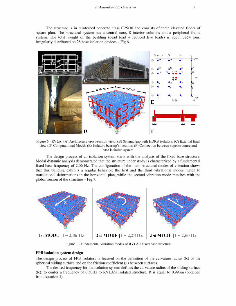
The structure is in reinforced concrete class C25/30 and consists of three elevated floors of
square plan. The structural system has a central core, 8 interior columns and a peripheral frame
system. The total weight of the building (dead load + reduced live loads) is about 3854 tons,
irregularly distributed on 28 base isolation devices – Fig.6.
Figure 6 - RVLA: (A) Architecture cross-section view; (B) Seismic gap with HDRB isolators; (C) External final
view (D) Computational Model; (E) Isolators bearing’s location; (F) Connection between superstructure and
base isolation system
The design process of an isolation system starts with the analysis of the fixed base structure.
Modal dynamic analysis demonstrated that the structure under study is characterized by a fundamental
fixed base frequency of 2,06 Hz. The configuration of the main structural modes of vibration shows
that this building exhibits a regular behavior: the first and the third vibrational modes match to
translational deformations in the horizontal plan, while the second vibration mode matches with the
global torsion of the structure – Fig.7.
Figure 7 - Fundamental vibration modes of RVLA’s fixed base structure
FPB isolation system design
The design process of FPB isolators is focused on the definition of the curvature radius (R) of the
spherical sliding surface and on the friction coefficient (µ) between surfaces.
The desired frequency for the isolation system defines the curvature radius of the sliding surface
(R): to confer a frequency of 0,50Hz to RVLA’s isolated structure, R is equal to 0,993m (obtained
from equation 1).
6
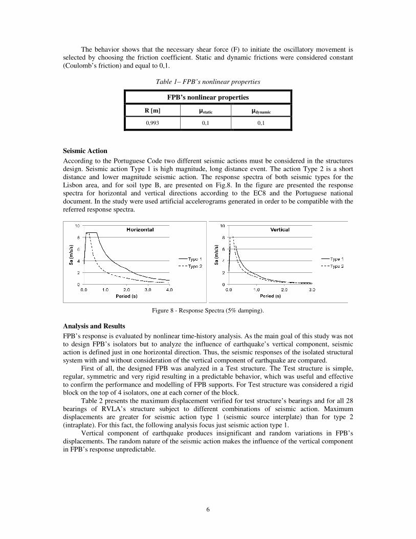
The behavior shows that the necessary shear force (F) to initiate the oscillatory movement is
selected by choosing the friction coefficient. Static and dynamic frictions were considered constant
(Coulomb’s friction) and equal to 0,1.
Table 1– FPB’s nonlinear properties
FPB’s nonlinear properties
R [m] µstatic µdynamic
0,993 0,1 0,1
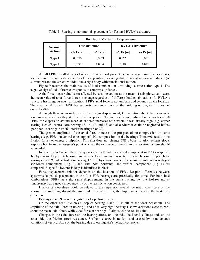
Seismic Action
According to the Portuguese Code two different seismic actions must be considered in the structures
design. Seismic action Type 1 is high magnitude, long distance event. The action Type 2 is a short
distance and lower magnitude seismic action. The response spectra of both seismic types for the
Lisbon area, and for soil type B, are presented on Fig.8. In the figure are presented the response
spectra for horizontal and vertical directions according to the EC8 and the Portuguese national
document. In the study were used artificial accelerograms generated in order to be compatible with the
referred response spectra.
Figure 8 - Response Spectra (5% damping).
Analysis and Results
FPB’s response is evaluated by nonlinear time-history analysis. As the main goal of this study was not
to design FPB’s isolators but to analyze the influence of earthquake’s vertical component, seismic
action is defined just in one horizontal direction. Thus, the seismic responses of the isolated structural
system with and without consideration of the vertical component of earthquake are compared.
First of all, the designed FPB was analyzed in a Test structure. The Test structure is simple,
regular, symmetric and very rigid resulting in a predictable behavior, which was useful and effective
to confirm the performance and modelling of FPB supports. For Test structure was considered a rigid
block on the top of 4 isolators, one at each corner of the block.
Table 2 presents the maximum displacement verified for test structure’s bearings and for all 28
bearings of RVLA’s structure subject to different combinations of seismic action. Maximum
displacements are greater for seismic action type 1 (seismic source interplate) than for type 2
(intraplate). For this fact, the following analysis focus just seismic action type 1.
Vertical component of earthquake produces insignificant and random variations in FPB’s
displacements. The random nature of the seismic action makes the influence of the vertical component
in FPB’s response unpredictable.
F. Amaral and L. Guerreiro 7
Table 2 –Bearing’s maximum displacement for Test and RVLA’s structure.
Bearing’s Maximum Displacement
Seismic
Action
Test structure RVLA’s structure
w/o Ez [m] w/ Ez [m] w/o Ez [m] w/ Ez [m]
Type 1 0,0070 0,0071 0,062 0,061
Type 2 0,0033 0,0034 0,018 0,019
All 28 FPBs installed in RVLA’s structure almost present the same maximum displacements,
for the same instant, independently of their position, showing that torsional motion is reduced (or
eliminated) and the structure slides like a rigid body with translational motion.
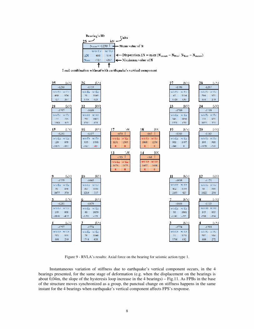
Figure 9 resumes the main results of load combinations involving seismic action type 1. The
negative sign of axial forces corresponds to compression forces.
Axial force mean value is not affected by seismic action: as the mean of seismic wave is zero,
the mean value of axial force does not change regardless of different load combinations. As RVLA’s
structure has irregular mass distribution, FPB’s axial force is not uniform and depends on the location.
The mean axial force in FPB that supports the central core of the building is low, i.e. it does not
exceed 750kN.
Although there is no influence in the design displacement, the variation about the mean axial
force increases with earthquake’s vertical component. The increase is not uniform but occurs for all 28
FPBs: the dispersion around mean axial force increases both where it was already high (e.g. corner
bearing 1 or 25, central core bearing 13, 14, 17, and 18) and also where it could be neglected before
(peripheral bearings 2 or 26, interior bearings 6 or 22).
The greater amplitude of the axial force increases the prospect of no compression on some
bearings (e.g. FPBs on central core support). No compression on the bearings (Nmax=0) result in no
friction forces or energy dissipation. This fact does not change FPB’s base isolation system global
response but, from the designer's point of view, the existence of tension in the isolation system should
be avoided.
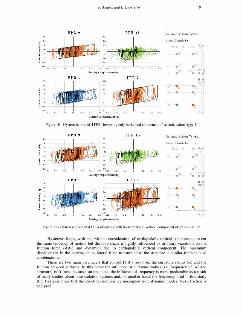
In order to understand the consequences of earthquake’s vertical component in FPB’s response,
the hysteresis loop of 4 bearings in various locations are presented: corner bearing 1, peripheral
bearings 2 and 9 and central core bearing 13. The hysteresis loops for a seismic combination with just
horizontal components (Fig.10) and with both horizontal and vertical component (Fig.11) are
compared. A specific hysteresis loop is identified in black.
Force-displacement relation depends on the location of FPBs. Despite differences between
hysteresis loops, displacements in the four FPB bearings are practically the same. For both load
combinations, FPBs have the same displacements in the same instant, i.e. the isolator moves
synchronized as a group independently of the seismic action considered.
Hysteresis loop shape could be related to the dispersion around the mean axial force on the
bearing: the more significant the amplitude in axial load is, the larger imperfections the hysteresis
curve has.
Bearings 2 and 9 present a hysteresis loop close to ideal.
On the other hand, hysteresis loop of bearing 1 and 13 is out of the ideal behaviour. The
amplitude of the axial force in bearing 1 and 13 is very high: bearing 1 show variations close to 50%
about the mean axial force, while axial force in bearings 13 almost duplicates its value.
Changes in the axial force on the bearing affect, on one side, the lateral stiffness and, on the
other side, the friction force resistance. Stiffness change is random and caused by instantaneous
variations of vertical force on the bearing due to earthquake’s vertical component.
8
Figure 9 - RVLA’s results: Axial force on the bearing for seismic action type 1.
Instantaneous variation of stiffness due to earthquake’s vertical component occurs, in the 4
bearings presented, for the same stage of deformation (e.g. when the displacement on the bearings is
about 0,04m, the slope of the hysteresis loop increase in the 4 bearings) – Fig.11. As FPBs in the base
of the structure moves synchronized as a group, the punctual change on stiffness happens in the same
instant for the 4 bearings when earthquake’s vertical component affects FPS’s response.
F. Amaral and L. Guerreiro 9
Figure 10 - Hysteresis loop of 4 FPBs involving only horizontal component of seismic action (type 1)
Figure 11 - Hysteresis loop of 4 FPBs involving both horizontal and vertical component of seismic action
Hysteresis loops, with and without consideration of earthquake’s vertical component, present
the same tendency of motion but the loop shape is lightly influenced by arbitrary variations on the
friction force (static and dynamic) due to earthquake’s vertical component. The maximum
displacement in the bearing or the lateral force transmitted to the structure is similar for both load
combinations.
There are two main parameters that control FPB’s response: the curvature radius (R) and the
friction between surfaces. In this paper the influence of curvature radius (i.e. frequency of isolated
structure) isn’t focus because, on one hand, the influence of frequency is more predictable as a result
of many studies about base isolation systems and, on another hand, the frequency used in this study
(0,5 Hz) guarantees that the structural motions are uncoupled from dynamic modes. Next, friction is
analyzed.
10
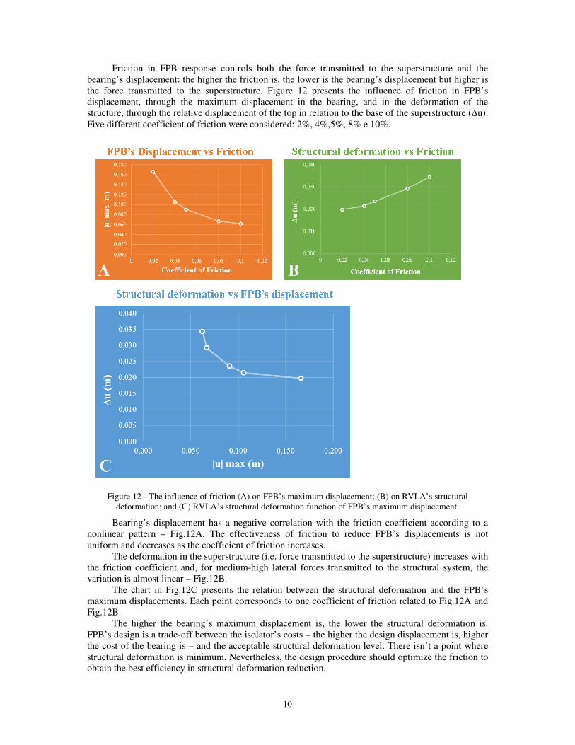
Friction in FPB response controls both the force transmitted to the superstructure and the
bearing’s displacement: the higher the friction is, the lower is the bearing’s displacement but higher is
the force transmitted to the superstructure. Figure 12 presents the influence of friction in FPB’s
displacement, through the maximum displacement in the bearing, and in the deformation of the
structure, through the relative displacement of the top in relation to the base of the superstructure (∆u).
Five different coefficient of friction were considered: 2%, 4%,5%, 8% e 10%.
Figure 12 - The influence of friction (A) on FPB’s maximum displacement; (B) on RVLA’s structural
deformation; and (C) RVLA’s structural deformation function of FPB’s maximum displacement.
Bearing’s displacement has a negative correlation with the friction coefficient according to a
nonlinear pattern – Fig.12A. The effectiveness of friction to reduce FPB’s displacements is not
uniform and decreases as the coefficient of friction increases.
The deformation in the superstructure (i.e. force transmitted to the superstructure) increases with
the friction coefficient and, for medium-high lateral forces transmitted to the structural system, the
variation is almost linear – Fig.12B.
The chart in Fig.12C presents the relation between the structural deformation and the FPB’s
maximum displacements. Each point corresponds to one coefficient of friction related to Fig.12A and
Fig.12B.
The higher the bearing’s maximum displacement is, the lower the structural deformation is.
FPB’s design is a trade-off between the isolator’s costs – the higher the design displacement is, higher
the cost of the bearing is – and the acceptable structural deformation level. There isn’t a point where
structural deformation is minimum. Nevertheless, the design procedure should optimize the friction to
obtain the best efficiency in structural deformation reduction.
F. Amaral and L. Guerreiro 11
CONCLUSIONS
The influence of the vertical component of the earthquake on FPB’s response was studied by
application in a real structure. Based on the various studies performed the following is concluded:
1. Earthquake’s vertical component has no influence on the value of the maximum displacement
of FPB (for both types of seismic action 1-interplate or 2-intraplate). The variation on the bearing’s
displacement is insignificant and arbitrary (unpredictable).
2. Structure’s deformation pattern is not influenced by earthquake’s vertical component. FPBs
move synchronized as a group, independently of the load combination. Structural torsion is practically
annulled by FPB isolation system and the structure moves as a rigid body in translational motion.
3. The mean value of axial force on the FPBs isn’t influenced by earthquake’s vertical
component. Despite the constant change of the seismic waves’ sign, the mean value of the vertical
seismic acceleration is zero and therefore has no influence on the average value of the axial force in
the FPB support.
4. The variation about the mean axial force increases with earthquake’s vertical component. The
increase is not uniform but takes place for all FPBs. The changes in the axial force on the bearing
affect both lateral stiffness and friction force resistance. However, the envelope of force-displacement
FPB’s response is almost not influenced by earthquake’s vertical component.
5. The greater amplitude of the axial force increases the probability of no compression on the
bearings. This fact does not change FPB’s base isolation system global response but, from the
designer's point of view, the existence of tension in the isolation system should be avoided and the
solution should be studied.
6. The influence of friction in FPB’s response is not affected by earthquake’s vertical
component. FPB’s design should choose the most effective friction in the reduction of structural
deformation, keeping bearing’s displacement in acceptable levels. In the iterative design procedure,
the radius of the concave surface should be optimized according to the desirable frequency.
The analysis suggests that the influence of the vertical component of earthquake on FPB’s
response may be extended to new cases of study, considering extreme cases such as irregular and tall
structures. Future developments should include case studies constrained by seismic action type 2
(intraplate – near field fault). In addition, the latest developments in FPB isolation systems could be
further studied, in particular the sliding materials with frictional coefficient dependent on the surface
pressure of the bearing and the new FPB isolation systems with multiple sliding surfaces
REFERENCES
Amaral, F. (2013) – “Análise da componente vertical da acção sísmica na resposta de Apoios Pendulares com
Atrito”, MSc Thesis, Instituto Superior Técnico - Universidade Técnica de Lisboa
CSI (2010) – “Analysis Reference Manual for SAP2000, ETABS, SAFE and CSiBridge”, Berkeley, USA
Chaudhari, M. D.; Goyal, A. (2004) - “Seismic performance enhancement of bridges using Sliding Friction
Isolators mounted on flexible supports”, 13ª WCEE, Vancouver, Canada
Eröz, M.; DesRoches, R. (2008) – “Bridge seismic response function of FPS modeling assumptions”, EE
Hacheem, Z. A.; AL-Shimmari, I. K. (2010) - “Finite element analysis of a friction pendulum bearing base
isolation system for earthquake loads”, Vol. 16
Huber; P.; Roos; R. (2013) - “Sliding Pendulum bearing”, US Patent 8371075 B2
Jangid, R.S. (2004) – “Optimum friction pendulum system for near-fault motions”, ES, Vol. 27
Kravchuk, N.; Colquhoun, R.; Porbaha, A. (2008) - "Development of a Friction Pendulum Bearing Base
Isolation System for Earthquake Engineering Education”, ASEE
Marioni, A. (2010) – “The use of sliding pendulum isolators for the C.A.S.E. project in L’Aquila”, Italy
Mokha, A., Amin, N., Constantinou, M., and Zayas, V. (1996) - ”Seismic Isolation Retrofit of Large Historic
Building.”, Journal of Structural Engineering, Vol. 122, Issue 3
Symans, M. D. (2013) – “Seismic Protective Systems: Seismic Isolation”, RPI, FEMA, accessed July 2013.
Zayas, V., inventor (1987) – “Earthquake Protective Column Support”, US Patent 4644714 A, 24 February
Zayas, V.; Low, S.; Mahin, S. (1990) – “A Simple Pendulum Technique for Achieving Seismic Isolation.”
Earthquake Spectra, Vol. 6, No. 2, May
Zayas, V.; Low, S. (2006) - “Sliding Pendulum Seismic Isolation System”, US 2006/0174555 A1, August