Embed Size (px)
Citation preview
International Journal of Scientific and Research Publications, Volume 3, Issue 3, March 2013 1 ISSN 2250-3153
www.ijsrp.org
Effect of Very Fast Transient over voltages at high
frequency in a Gas Insulated Substation during switching
operations
Dr Sukhdeo Sao*, K Prasada Rao
**
* EEE Dept.,Bharat Institute of Engineering & Technology,RR Dist. Hyderabad, AP, India
** EEE Dept.,Christu Jyothi Institute of Technology & Science, Jangaon, AP, India
Abstract- Due to the opening or closing of circuit breakers and
disconnect switches in Gas Insulated Substations (GIS),
especially in the pumped storage power stations, Very Fast
Transient Over-voltages (VFTO) are generated. This paper
describes the 500 kV and 750 kV GIS. The variations of VFTO
magnitudes at different points in 500 kV and 750 kV GIS during
different switching operations have been calculated and
compared by using Mat lab/Simulink. In this paper the effective
factors on the level of VFTO is investigated and the beneficial
approaches for the industry to finding the optimum approaches
for VFT mitigation is presented. These factors are included
residual charges, resistance, spark resistance and entrance
capacitance of transformer.
Index Terms- Gas Insulated Substation; Very Fast Transient
Over voltages; residual charges, spark resistance , entrance
capacitance, Mat lab/Simulink.
I. INTRODUCTION
he increase in demand for electricity and growing energy
density in metropolitan cities have made it necessary to
extend the existing high voltage networks right up to the
consumers . Stepping down the voltage from transmission to the
distribution level atthe substation located near the actual
consumers not only produces economic advantages, but also
ensures reliable power supply. The following are the main
reasons for use of gas insulated substation,GIS has small ground
space requirements. Gas insulated Substations have easy
maintenance (nearly zero Maintenance) Less field erection time
& less erection cost. For underground power house of Hydro
electric power project where space constraint is a major issue.
This paper describes the 500 kV and 750 kV GIS of the
pumped storage power station . The variations of VFTO
magnitudes at different points in 500 kV and 750 kV GIS during
different switching operations have been calculated and
compared by using Matlab/Simulink.
Very Fast Transients (VFT) belong to highest frequency
range of transients in power systems. These transients are
originated within a gas-insulated substation (GIS) any time there
is an instantaneous change in voltage. This generally occurs as
the result of the opening or closing of a disconnect switch, but
other events, such as the operation of a circuit breaker, the
closing of a grounding switch, or the occurrence of a fault, can
also cause VFT. These transients have a very short rise time, in
the range of 4 to 100 ns, and are normally followed by
oscillations having frequencies in the range of 1 to 50 MHz.
During the operation of the DS, a small capacitor
connecting to the breaker will be switched. The velocity of DS
contacts is small (generally more than 0.6s), before the
completely switching, the arc reignition or prestrike occurs,
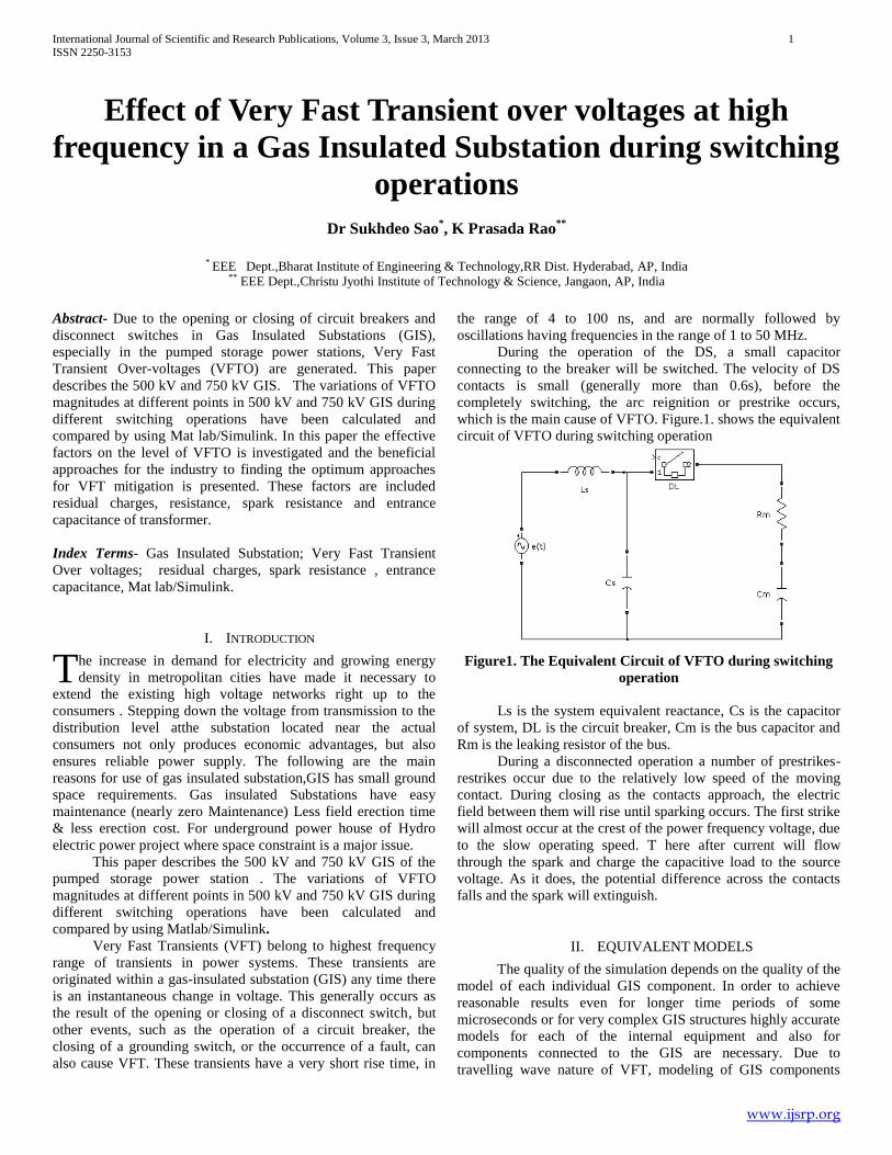
which is the main cause of VFTO. Figure.1. shows the equivalent
circuit of VFTO during switching operation
Figure1. The Equivalent Circuit of VFTO during switching
operation
Ls is the system equivalent reactance, Cs is the capacitor
of system, DL is the circuit breaker, Cm is the bus capacitor and
Rm is the leaking resistor of the bus.
During a disconnected operation a number of prestrikes-
restrikes occur due to the relatively low speed of the moving
contact. During closing as the contacts approach, the electric
field between them will rise until sparking occurs. The first strike
will almost occur at the crest of the power frequency voltage, due
to the slow operating speed. T here after current will flow
through the spark and charge the capacitive load to the source
voltage. As it does, the potential difference across the contacts
falls and the spark will extinguish.
II. EQUIVALENT MODELS
The quality of the simulation depends on the quality of the
model of each individual GIS component. In order to achieve
reasonable results even for longer time periods of some
microseconds or for very complex GIS structures highly accurate
models for each of the internal equipment and also for
components connected to the GIS are necessary. Due to
travelling wave nature of VFT, modeling of GIS components
T

International Journal of Scientific and Research Publications, Volume 3, Issue 3, March 2013 2
ISSN 2250-3153
www.ijsrp.org
make use of electrical equivalent circuits composed of lumped
elements and distributed parameters lines.
A GIS system comprising of an input cable, circuit
breakers, Dis-connector Switch, Bus bar, power transformer,
surge arrester. To simulate the Very Fast Transient over voltages
occur at Disconnect switch in GIS, Matlab is used. The
equivalent circuit of GIS is shown in figure 2.
Power transformer with bushing can be modeled by
entrance Capacitance where entrance capacitance has been
calculated in lightning test. Here the entrance capacitance of
power transformer should be kept as a 5000pF. The surge
impedance of a transmission Line is 350Ω and travel time is
300m/µs. The GIS Bus Bar can be represented as a lossless π-
line for a 50 Hz frequency. The surge impedance is 80 Ω and
travel time is 231m/µs [2]. The Cable can be represented as a
lossless π- line for a 50 Hz frequency. The surge impedance is
68.8 Ω and travel time is 103.8m/µs. Metal Oxide surge arresters
are used to protect medium and high voltage systems and
equipment against lightning and switching over-voltages.
The surge impedance of a transmission line can be
obtained from the relation
60lnb
Za
Ω
Capacitance
2
ln
o rCb
a
Inductance
ln
2
b
aL
H
Figure 2. The Equivalent diagram used for simulation
The MO Arrester obeys the equation
I KV , α>1
1
( ) ii ii
ref ref
V IK
V I
Where,
I current through arrester
V voltage across arrester
K ceramic constant (depending on arrester type)
α nonlinearity exponent (measure of nonlinearity).

International Journal of Scientific and Research Publications, Volume 3, Issue 3, March 2013 3
ISSN 2250-3153
www.ijsrp.org
The Characteristics of surge arresters are showed in Table 1
and Table 2
Table1. Characteristics of 444KV surge arrester
Table-2 Characteristics of 420 surge arrester
III. RESULTS & DISCUSSIONS
Against the difference of switch operation mode and their
position in GIS sub-station, we take three conditions to calculate
Very Fast Transient Over-voltages [VFTO]. Such operation
mode has two forms when opened and closed. When open
recovery voltage between contacts is much higher and VFTO is
higher correspondingly since the other contacts have residual
charges. So followed operations are pointed to opened operation
of DS.
A. VFTO caused by DS-50543.
When the Disconnect switch-50543 is opened before that
the switches DS-50546 and CB-5054 are already opened then the
VFTO level at Different points is shown in Table 3&4.
1) For 500 kV GIS
Source voltage is 550 kV.
Table.3: VFTO caused by operating of DS-50543 for 500kV
GIS.
Voltage to ground
of
bus-bar(kV)
V14s 535.1
V15s 572.4
V17s 706.3
Voltage to ground
of surge arrester
(kV)
V11UA 548.5
V12UA 630.7
V13UA 0.031
Voltage to ground
of Transformer
(kV)
VTR1 472.5
VTR3 476.1
VTR4 473.2
From data in table 3, we know that when opening of DS-
50543 the maximal voltage to ground of bus bar near the switch
reaches 1.73p.u.;the maximal voltage to ground of surge arrester
reaches 1.54p.u.;the maximal voltage to ground of transformer
reaches 1.16p.u.and the corresponding results are as follows.
Fig.3. Voltage to ground of bus bar at 14S.when opening of
DS-50543 for 500KV GIS
Fig 4. Voltage to ground of bus bar at 17Swhen opening of
DS-50543 for 500KV GIS
Fig5 Voltage to ground of surge arrester at the end of
transformer unit3&4 when opening of DS-50543 for 500KV
GIS
Current(A) Voltage(kV)
0.008 594.0
20.0 674.5
10000 932.0
Voltage(kV)
0.003 20000.0
628.0 1161.0

International Journal of Scientific and Research Publications, Volume 3, Issue 3, March 2013 4
ISSN 2250-3153
www.ijsrp.org
Fig6. Voltage to ground of surge arrester at the end of
transformer unit6 when opening ofDS-50543 for 500 KV GIS
Fig. 7 Voltage to ground of transformer at unit1 when
opening of DS-50543 for 500 kV GIS
Fig 8 Voltage to ground of transformer at unit 4 when
opening of DS-50543 for 500KV GIS
1) For 750 kV GIS
Source voltage is 750 kV.
Table-4
VFTO caused by operating of DS-50543 for 750kV GIS
From data in table 4, we know that when opening of DS-
50543 the maximal voltage to ground of bus bar near the switch
reaches 1.57p.u.;the maximal voltage to ground of surge arrester
reaches 1.40p.u.;the maximal voltage to ground of transformer
reaches 1.06p.u.and the corresponding results are as follows.
Fig.9. Voltage to ground of bus bar at 14S. when opening DS-
50543 for 750KV GIS
Fig.10. Voltage to ground of bus bar at 17S when opening
DS-50543 for 750 KV GIS
Fig.11 Voltage to ground of surge arrester at the end of
transformer unit3&4 when opening DS-50543 for 750 kV
GIS.
Voltage to ground
of bus bar (kV)
V14s 729.7
V15s 780.5
V17s 963.1
Voltage to ground
of surge arrester
(kV)
V11UA 748
V12UA 860.1
V13UA 0.032
Voltage to ground
of Transformer
(kV)
VTR1 644.3
VTR3 649.3
VTR4 645.2

International Journal of Scientific and Research Publications, Volume 3, Issue 3, March 2013 5
ISSN 2250-3153
www.ijsrp.org
Fig12. Voltage to ground of surge arrester at the end of
transformer unit6 when opening DS-50543 for 750 KV GIS
Fig 13Voltage to ground of transformer at unit 3 when
opening of DS-50543 for 750 KV GIS
Fig 14Voltage to ground of transformer at unit 4 when
0pening of DS-50543 for 750 KV GIS
Fig. 15 Equivalent simulink model of GIS when opening of DS-50543

International Journal of Scientific and Research Publications, Volume 3, Issue 3, March 2013 6
ISSN 2250-3153
www.ijsrp.org
Fig 16

International Journal of Scientific and Research Publications, Volume 3, Issue 3, March 2013 7
ISSN 2250-3153
www.ijsrp.org
Fig .17 Equivalent simulink model of GIS system when opening of DS-50121 but DS-50122 is closed
Fig. 18Equivalent simulink model of influence of residual charges on VFTO
International Journal of Scientific and Research Publications, Volume 3, Issue 3, March 2013 8
ISSN 2250-3153
www.ijsrp.org
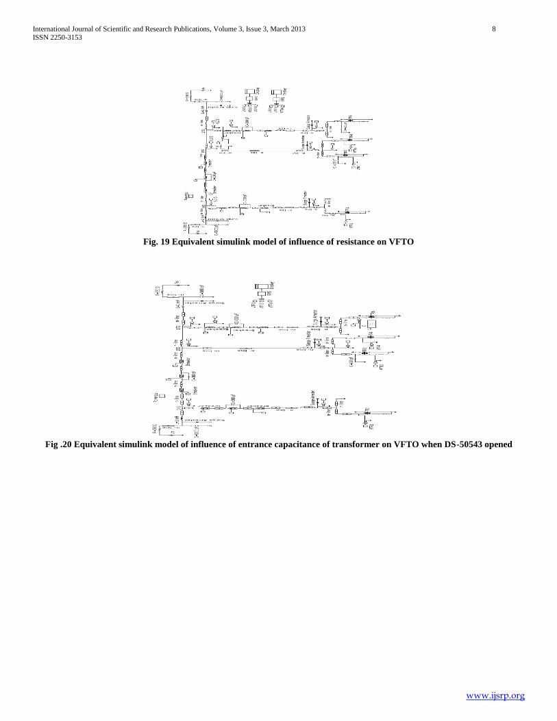
Fig. 19 Equivalent simulink model of influence of resistance on VFTO
Fig .20 Equivalent simulink model of influence of entrance capacitance of transformer on VFTO when DS-50543 opened

International Journal of Scientific and Research Publications, Volume 3, Issue 3, March 2013 9
ISSN 2250-3153
www.ijsrp.org
Fig.21 Equivalent simulink model of influence of entrance capacitance of transformer on VFTO when DS-50121 opened
B. VFTO caused by DS-50121 when DS-50122 open
When the Disconnect switch-50121 is opened before that
the switches DS-50122 and CB-5012 are already opened then the
VFTO level at Different points is shown in Table 5&6.
1) For 500 kV GIS
Table-5
VFTO caused by opening of DS-50121 open for 500kV GIS
Voltage to ground of
bus bar (kV)
V14s
712.5
Voltage to ground of
surge arrester (kV)
V11UA
676
Voltage to ground of
transformer(kV)
VTR1
493.9
From data in table 5, we know that when opening of DS-
50121 level of over voltages is much higher due to few current
shunts circuit. The maximal voltage to ground of bus bar near the
switch reaches 1.75p.u;the maximal voltage to ground of surge
arrester reaches 1.65p.u.;the maximal voltage to ground of
transformer reaches 1.20p.u
1) For 750 kV GIS
Source voltage is 750 kV
Table-6
VFTO caused by opening of DS-50121 open for 750kV GIS
VFTO caused by opening of DS-50121 open for 750kV GIS
From data in table-6, the maximal voltage to ground of bus bar
Voltage to ground of
bus bar (kV)
V14s
971.5
Voltage to ground of
surge arrester (kV)
V11UA
921.9
Voltage to ground of
transformer(kV)
VTR1
673.5
International Journal of Scientific and Research Publications, Volume 3, Issue 3, March 2013 10
ISSN 2250-3153
www.ijsrp.org
near the switch reaches 1.58p.u;the maximal voltage to ground of
surge arrester reaches 1.50p.u.;the maximal voltage to ground of
transformer reaches 1.09p.u.
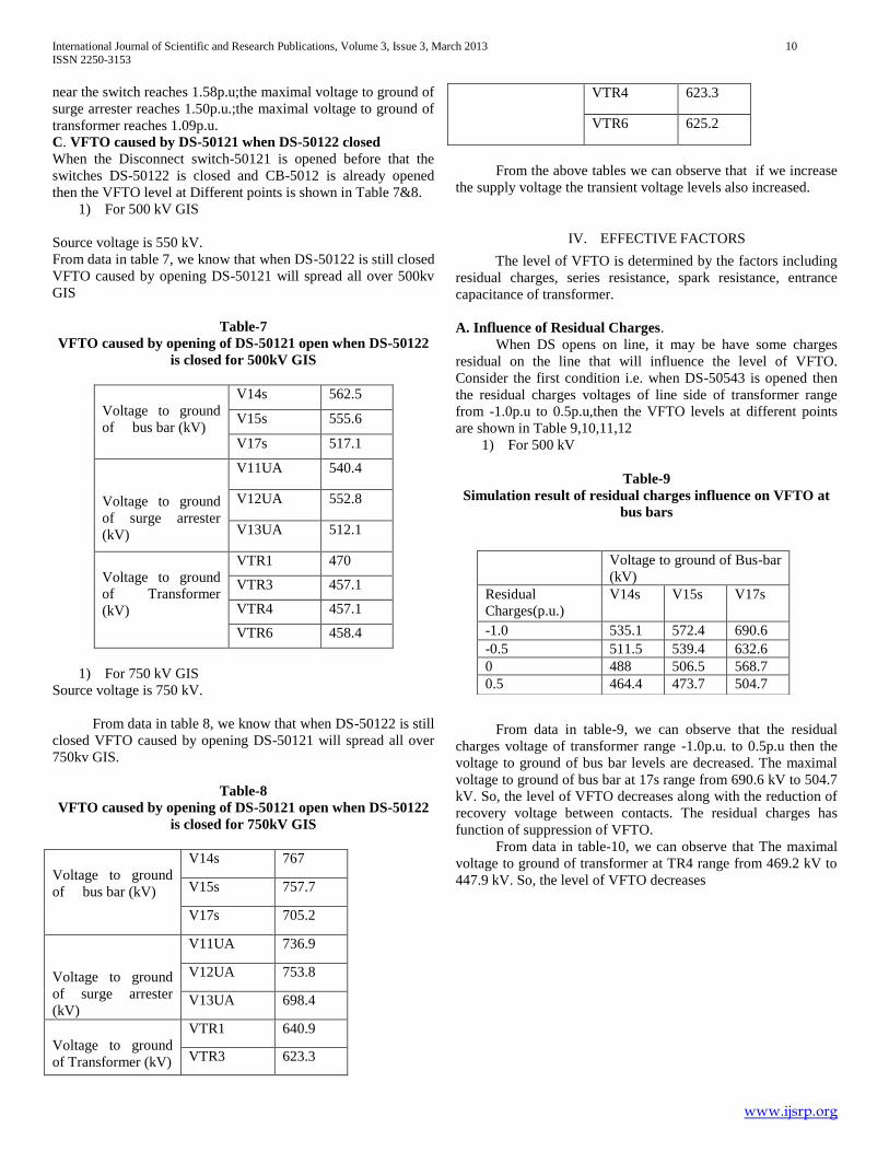
C. VFTO caused by DS-50121 when DS-50122 closed
When the Disconnect switch-50121 is opened before that the
switches DS-50122 is closed and CB-5012 is already opened
then the VFTO level at Different points is shown in Table 7&8.
1) For 500 kV GIS
Source voltage is 550 kV.
From data in table 7, we know that when DS-50122 is still closed
VFTO caused by opening DS-50121 will spread all over 500kv
GIS
Table-7
VFTO caused by opening of DS-50121 open when DS-50122
is closed for 500kV GIS
Voltage to ground
of bus bar (kV)
V14s 562.5
V15s 555.6
V17s 517.1
Voltage to ground
of surge arrester
(kV)
V11UA 540.4
V12UA 552.8
V13UA 512.1
Voltage to ground
of Transformer
(kV)
VTR1 470
VTR3 457.1
VTR4 457.1
VTR6 458.4
1) For 750 kV GIS
Source voltage is 750 kV.
From data in table 8, we know that when DS-50122 is still
closed VFTO caused by opening DS-50121 will spread all over
750kv GIS.
Table-8
VFTO caused by opening of DS-50121 open when DS-50122
is closed for 750kV GIS
Voltage to ground
of bus bar (kV)
V14s 767
V15s 757.7
V17s 705.2
Voltage to ground
of surge arrester
(kV)
V11UA 736.9
V12UA 753.8
V13UA 698.4
Voltage to ground
of Transformer (kV)
VTR1 640.9
VTR3 623.3
VTR4 623.3
VTR6 625.2
From the above tables we can observe that if we increase
the supply voltage the transient voltage levels also increased.
IV. EFFECTIVE FACTORS
The level of VFTO is determined by the factors including
residual charges, series resistance, spark resistance, entrance
capacitance of transformer.
A. Influence of Residual Charges.
When DS opens on line, it may be have some charges
residual on the line that will influence the level of VFTO.
Consider the first condition i.e. when DS-50543 is opened then
the residual charges voltages of line side of transformer range
from -1.0p.u to 0.5p.u,then the VFTO levels at different points
are shown in Table 9,10,11,12
1) For 500 kV
Table-9
Simulation result of residual charges influence on VFTO at
bus bars
From data in table-9, we can observe that the residual
charges voltage of transformer range -1.0p.u. to 0.5p.u then the
voltage to ground of bus bar levels are decreased. The maximal
voltage to ground of bus bar at 17s range from 690.6 kV to 504.7
kV. So, the level of VFTO decreases along with the reduction of
recovery voltage between contacts. The residual charges has
function of suppression of VFTO.
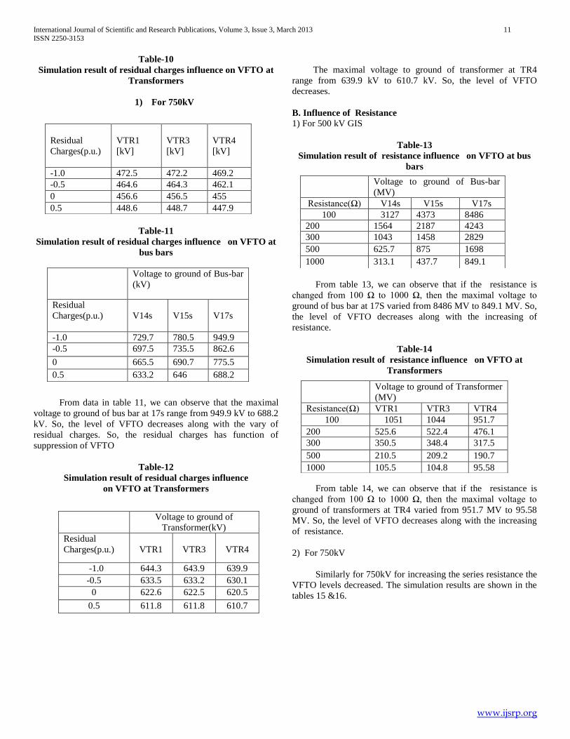
From data in table-10, we can observe that The maximal
voltage to ground of transformer at TR4 range from 469.2 kV to
447.9 kV. So, the level of VFTO decreases
Voltage to ground of Bus-bar
(kV)
Residual
Charges(p.u.)
V14s V15s V17s
-1.0 535.1 572.4 690.6
-0.5 511.5 539.4 632.6
0 488 506.5 568.7
0.5 464.4 473.7 504.7
International Journal of Scientific and Research Publications, Volume 3, Issue 3, March 2013 11
ISSN 2250-3153
www.ijsrp.org
Table-10
Simulation result of residual charges influence on VFTO at
Transformers
1) For 750kV
Table-11
Simulation result of residual charges influence on VFTO at
bus bars
From data in table 11, we can observe that the maximal
voltage to ground of bus bar at 17s range from 949.9 kV to 688.2
kV. So, the level of VFTO decreases along with the vary of
residual charges. So, the residual charges has function of
suppression of VFTO
Table-12
Simulation result of residual charges influence
on VFTO at Transformers
The maximal voltage to ground of transformer at TR4
range from 639.9 kV to 610.7 kV. So, the level of VFTO
decreases.
B. Influence of Resistance
1) For 500 kV GIS
Table-13
Simulation result of resistance influence on VFTO at bus
bars
From table 13, we can observe that if the resistance is
changed from 100 Ω to 1000 Ω, then the maximal voltage to
ground of bus bar at 17S varied from 8486 MV to 849.1 MV. So,
the level of VFTO decreases along with the increasing of
resistance.
Table-14
Simulation result of resistance influence on VFTO at
Transformers
From table 14, we can observe that if the resistance is
changed from 100 Ω to 1000 Ω, then the maximal voltage to
ground of transformers at TR4 varied from 951.7 MV to 95.58
MV. So, the level of VFTO decreases along with the increasing
of resistance.
2) For 750kV
Similarly for 750kV for increasing the series resistance the
VFTO levels decreased. The simulation results are shown in the
tables 15 &16.
Residual
Charges(p.u.)
VTR1
[kV]
VTR3
[kV]
VTR4
[kV]
-1.0 472.5 472.2 469.2
-0.5 464.6 464.3 462.1
0 456.6 456.5 455
0.5 448.6 448.7 447.9
Voltage to ground of Bus-bar
(kV)
Residual
Charges(p.u.)
V14s
V15s
V17s
-1.0 729.7 780.5 949.9
-0.5 697.5 735.5 862.6
0 665.5 690.7 775.5
0.5 633.2 646 688.2
Voltage to ground of
Transformer(kV)
Residual
Charges(p.u.)
VTR1
VTR3
VTR4
-1.0 644.3 643.9 639.9
-0.5 633.5 633.2 630.1
0 622.6 622.5 620.5
0.5 611.8 611.8 610.7
Voltage to ground of Bus-bar
(MV)
Resistance(Ω) V14s V15s V17s
100 3127 4373 8486
200 1564 2187 4243
300 1043 1458 2829
500 625.7 875 1698
1000 313.1 437.7 849.1
Voltage to ground of Transformer
(MV)
Resistance(Ω) VTR1 VTR3 VTR4
100 1051 1044 951.7
200 525.6 522.4 476.1
300 350.5 348.4 317.5
500 210.5 209.2 190.7
1000 105.5 104.8 95.58

International Journal of Scientific and Research Publications, Volume 3, Issue 3, March 2013 12
ISSN 2250-3153
www.ijsrp.org
Table-15
Simulation result of resistance influence on VFTO at bus
bars
Table-16
Simulation result of resistance influence on VFTO at
Transformers
C. INFLUENCE OF SPARK RESISTANCE
When restriking transient happens, spark resistance can
have effect on damping over voltages. Spark resistance is an
exponentially decaying resistance. Table 17, 18, 19 and 20 are
the simulation results of the spark resistance influence of VFTO.
1) For 500 kV GIS
Source voltage is 550 kV.
Table-17
Simulation result of spark resistance influence on VFTO at
bus bars
From data in table 17, we can observe that if the spark
resistance is varied from 0.1 to 200 Ω then the maximum voltage
to ground of bus bar at 17s varied from 701.3 to 436.7 kV.
similarly the maximum voltage to ground of transformer varied
from 478.4 to 445.9 kV. So, the VFTO levels decreased along
with the increasing the spark resistance.
Table-18
Simulation result of spark resistance
influence on VFTO at transformers
Table-19
Simulation result of spark resistance influence on VFTO at
bus bars
Table-20
Simulation result of spark resistance
influence on VFTO at transformers
D.INFLUENCE OF ENTRANCE CAPACITANCE OF
TRANSFORMER
The simulation results transformer entrance capacitance
influence of VFTO is shown in tables 21,22,23,24.
1) When DS-50543 opened
a) For 500 kV GIS.
Voltage to ground of Bus-bar
(MV)
Resistance(Ω)
V14s V15s V17s
100 4264 5963 11570
200 2132 2982 5786
300 1422 1988 3858
500 853.3 1193 2315
1000 427 595.9 1158
Voltage to ground of Transformer
(MV)
Resistance(Ω)
VTR1
VTR3
VTR4
100 1433 1424 1298
200 715.7 712.3 649.2
300 478 475.1 433
500 287.1 285.3 260.1
1000 143.8 143 130.3
Voltage to ground of Bus-
bar (kV)
Spark
Resistance(Ω)
V14s
V15s
V17s
0.1 732.8 783.2 956.3
25 729.7 780.5 950
10 721.3 772.4 931.9
50 689.8 738.8 861.1
100 650 697.1 772.6
200 571.9 613.4 595.5
Voltage to ground of
Transformer(kV)
Spark
Resistance(Ω)
VTR1 VTR3 VTR4
0.1 472.8 472.7 478.4
25 472.5 472.2 469.3
10 471.4 470.9 468.2
50 466.6 465.5 463.5
100 460.0 458.8 457.6
200 448.6 445.3 445.9
Voltage to ground of Bus-
bar (kV)
Spark
Resistance(Ω)
V14s
V15s
V17s
0.1 537.4 574.4 701.3
25 535.1 572.4 696.7
10 528.9 566.4 683.4
50 505.9 541.9 631.5
100 477 511.2 566.6
200 419.4 449.9 436.7
Spark
Resistance(Ω)
VTR1
[kV]
VTR3
[kV]
VTR4
[kV]
0.1 644.7 644.6 652.4
25 644.3 643.9 639.9
10 642.8 642.2 638.4
50 636.3 634.8 632
100 628.1 625.6 624.1
200 611.7 607.2 608.1

International Journal of Scientific and Research Publications, Volume 3, Issue 3, March 2013 13
ISSN 2250-3153
www.ijsrp.org
Table-21
Simulation result of transformer entrance capacitance
influence on VFTO when DS-50543 opened.
Voltage to ground of
Transformer(kV)
Transformer
Entrance
Capacitance(pF)
VTR1
VTR3
VTR4
5000 453.3 458.2 456.6
10000 455.8 461.2 458.9
15000 472.4 472.2 469.2
20000 450.9 455.1 454.2
25000 448.4 452 451.9
From data in table-21, we can observe that the entrance
capacitance is changed from 5000 to 25000 pF, then the max.
voltage to ground of transformer is changed from 456.6 kV to
451.9 kV, So, the VFTO levels decreased along with the
increasing the entrance capacitance of transformer.
a) For 750 kV.
Similarly in 750kV, the VFTO levels decreased along
with the increasing the entrance capacitance of transformer.
Table-22
Simulation result of transformer entrance capacitance
influence on VFTO when DS-50543 opened
2) When DS-50121 opened(DS-50122 closed)
a) For 500 kV
Table-23
Simulation result of transformer entrance capacitance
influence on VFTO when DS-50543 opened
a) For 750 kV
Table-24
Simulation result of transformer entrance capacitance
influence on VFTO when DS-50543 opened
V. CONCLUSION
The 500 kV and 750 kV Gas Insulated Substation system
had been modeled and studied for VFTO‟s by using
Matlab/simulink.
It can be concluded that as the source voltage is increased
the VFTO levels also increased and also conclude that the factors
residual charges, Spark resistance, resistance and the entrance
capacitance have functions of Suppression of VFTO.
REFERENCES
[1] Lu Tiechen, Zhang Bo,”Calculation of Very Fast Transient Overvoltage in GIS”, IEEE/PES Conference on Transmission and Distribution,Vol.4,2005, pp.1-5.
[2] J.A. Martinez, P. Chowdhuri, R. Iravani, A. Keri, D. Povh,” Modelling guidelines for very fast transients in Gas Insulated substations”, IEEE working group on modeling and analysis of system transients
[3] Christos A. Christodoulou, Fani A. Assimakopoulou, Ioannis F. Gonos, Ioannis A. Stathopulos,” Simulation of Metal Oxide Surge Arresters Behavior” IEEE Transactions on High voltage, Vol.1,pp. 1862-1866, 2008.
[4] V. Vinod Kumar, Joy Thomas M. and M. S. Naidu, “VFTO Computation in a 420kV GIS”, Eleventh International Symposium on High Voltage Engineering, (Conf. Publ. No. 467),Vol.1,pp.319-322,1999.
[5] J. Meppelink, K. Diederich, K. Feser and D.W. Pfaff, "Very fast transients in GIS", IEEE Transactions On Power Delivery, vol. 4, no. 1, pp. 223-233, January 1989.
[6] Boggs S.A., Chu F.Y and Fujimoto N., „Disconnect Switch Induced Transients and Trapped charge in GIS‟, IEEE Trans. PAS, Vol. PAS-101, No.10, PP.3593-3601,1982
[7] .Y. Shibuya, S. Fuji, and N. Hosokawa, “ Analysis of very fast transient over voltage in transformer winding”, IEE Proc. Generation transmission and distribution, Vol.144,No.5,1997,pp.461-468. Fig.
AUTHORS
First Author – Dr sukhdeo sao ,professor , EEE Dept.,Bharat
Institute of Engineering & Technology,RR Dist.
HYDERABAD,AP,India,[email protected]
Voltage to ground of
Transformer(kV)
Transformer
Entrance
Capacitance(pF)
VTR1
VTR3
VTR4
5000 644.2 643.9 639.8
10000 621.5 628.9 625.8
15000 618.2 624.8 622.6
20000 614.8 620.6 619.4
25000 611.5 616.4 616.2
Voltage to ground of Transformer(kV)
C (pF) VTR1 VTR3 VTR4 VTR6
5000 470 457.1 457.1 458.4
10000 458.9 449.7 449.7 451.2
15000 456.6 447 446.9 448.7
20000 454.3 444.2 444 446.3
25000 452 441.4 441.2 443.8
Voltage to ground of Transformer(kV)
C(pF) VTR1 VTR3 VTR4 VTR6
5000 640.9 623.3 623.3 625.1
10000 625.8 613.3 613.2 615.3
15000 622.7 609.5 609.4 611.9
20000 619.5 605.7 605.5 608.6
25000 616.3 601.9 601.6 605.2

International Journal of Scientific and Research Publications, Volume 3, Issue 3, March 2013 14
ISSN 2250-3153
www.ijsrp.org
Second Author – k prasada rao ,research scholar and associate
professor,EEE Dept.,Christu Jyothi Institute of Technology &
Science,Jangaon,AP,India,Email: [email protected]