Embed Size (px)
Citation preview

Effective dispersion of graphene nanoplatelets in epoxy grout for pipeline rehabilitationK. S. Lim, A. S. Kasmaon, S. C. Chin, and S. I. Doh
Citation: AIP Conference Proceedings 2020, 020036 (2018); doi: 10.1063/1.5062662View online: https://doi.org/10.1063/1.5062662View Table of Contents: http://aip.scitation.org/toc/apc/2020/1Published by the American Institute of Physics
Effective Dispersion of Graphene Nanoplatelets in Epoxy Grout for Pipeline Rehabilitation
K. S. Lim 1, a), A. S. Kasmaon1, b), S. C. Chin1, c) and S. I. Doh1, d)
1Faculty of Civil Engineering and Earth Resources, Universiti Malaysia Pahang, 26300 Gambang, Kuantan, Pahang, MALAYSIA.
a) Corresponding author: [email protected]) [email protected]
c) [email protected]) [email protected]
Abstract. After years of operation, oil and gas pipelines are subjected to various damage mechanisms such as third party damage, material defect, and corrosion. These damaged pipelines need to be repaired/rehabilitated to ensure safe operation in the future. Nowadays, numerous rehabilitation techniques and repair methods are available for onshore and offshore pipelines including the usage of Fibre-Reinforced Polymer composite. A composite repair system consists of three parts which are composite wrapper, adhesive and infill materials and it is the most preferable techniques in repairing damaged pipeline in oil and gas industry. High strength infill materials has the potential in improving overall repair performance of composite repair system. The purpose of this research is to investigate the effectiveness of graphene nanoplatelets as reinforcement to enhance the mechanical properties of epoxy grout used as infill materials by adding 0.01%, 0.05% and 0.1% of graphene nanoplatelets. The dispersion was done by calendaring technique using a three-roll mill machine where the graphene particles were de-agglomerated to achieve homogenous dispersion. The results of tensile and compression tests show increment of strength for all graphene-modified samples. The strength increment was recoded range from 23% to 50% and 9% to 22% under tensile and compression test, respectively. The highest tensile strength was recorded at 20.89 MPa for sample with 0.1% graphene while sample with 0.05% graphene shows 82.67 MPa in compressive strength. This signifies the effectiveness dispersion of graphene nanoplatelets as reinforcement in the epoxy grout. As a conclusion, graphene nanoplatelets has great potential to improve the mechanical properties of epoxy grout with the aid of proper dispersion process.
INTRODUCTION
Structure rehabilitation techniques involving repairing or upgrading pipelines systems in civil engineering applications are techniques that commonly used in oil and gas industry. Pipelines in oil and gas industry are being used to transport products such as oil and gas across various soil environments and from offshore to onshore plant. Most of the pipelines that have been used for transporting products are subjected to various types of damage after long service year [1-4]. The factors that contribute to the pipelines damage include corrosion, natural forces, construction defect and third party damage [5-7]. Obviously, pipeline surface that is exposed to water and soil environment will have higher corrosion risk due to active chemical reaction by its surrounding environment [8]. Most of the pipelines that have been operated for long duration and suffer from damages need repair and maintenance to ensure that it can operate smoothly and safely [9]. This is very important for the safety and economy purpose of public and pipeline operators.
Generally, repairing methods have been developed in order to extend the safety and durability of damaged pipeline. There are two ways to repair pipeline which are conventional steel sleeve and composite repair system [3]. Conventionally, pipelines are repaired by removing the entire damaged section or using steel sleeve/clamp to reinforce the damaged pipe. The conventional repair method has several disadvantages including safety issues due to hot work, bulky, have limited applications for joints or bends and subjected to corrosion risk in the future. The
Advances in Civil Engineering and Science TechnologyAIP Conf. Proc. 2020, 020036-1–020036-7; https://doi.org/10.1063/1.5062662
Published by AIP Publishing. 978-0-7354-1738-0/$30.00
020036-1
Clock Spring Company show that the composite pipe repairs are stronger than the original pipe, allowing the repaired pipe to perform at original Maximum Allowable Operating Pressure (MAOP) and it has been endorsed by peer review and third party testing in oil and gas industry [10]. A composite repair system generally consists of 3 components; composite wrap, infill material, and adhesive. The advantages of composite repair system include lightweight, high strength and stiffness, and good corrosion resistance. Even though composite repair systems offer numerous advantages, several issues regarding the performance of the composite repair systems are not fully understood. These issues include conservativeness in existing design codes, effect of defect geometry, and performance and contribution of infill materials [11,12]. In addition, the composite wrap which deemed as main strength contributor in the repair system could exhibit degradation over time when exposed to UV rays, moisture and high temperatures which may potentially leads to sudden failure before the FRP composite reach its full performance. Repair efficiency may be increase with the high performance infill material if it can be serve as second protection layer if failure of composite occurs. However, some of the researchers ignoring the function of the infill materials and mostly focused on the improvement and the performance of the composite wrapping component. These researchers assume that the epoxy grout used is only to fill the void/defect of the damaged pipeline without reinforcement on the pipeline. However, this assumption is not supported by any strong evidence.
Previous studies have pointed out that the infill has the potential to serve as load bearing component [12,13]. A higher performance infill may improve the overall repair performance. Since the discovery of graphene nanoplatelets, it have been widely used and proven effective in improving the mechanical properties of epoxy groutwith typical amount of graphene nanoplatelets added ranging from 0% to 2.5% [14-17]. Therefore, graphene nanoplatelets is considered suitable to be used as reinforcement in this research due to its extraordinary properties.Singhi stated that dispersion of nanofillers inside the epoxy resin can be very challenging for researchers. One of the reasons is the low viscosity of resin will cause poorer dispersion of nanofiller [17]. This is one of the reasons why this research needs to be conducted to achieve better result of dispersion. Therefore, this study aims to investigate the dispersion of the graphene nanoplatelets inside the epoxy composite and it is hypothesized that good dispersion will enhance the performance of the infill materials towards pipelines repair. With the enhancement of infill’s mechanical properties, it can potentially increase the overall load bearing capacity by the repair system.
RESEARCH METHODS
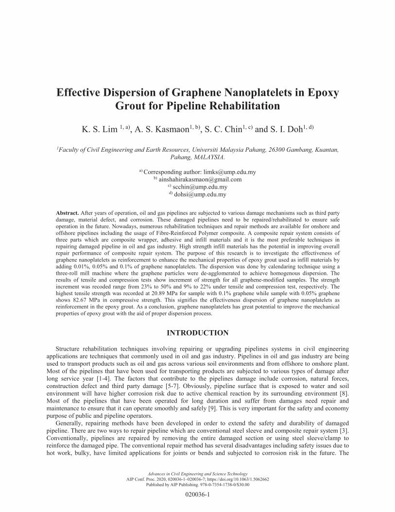
The infill used in this study is commercially available steel-filled epoxy grout. The modification of neat epoxy starts with mixing epoxy resin and graphene nanoplatelets using planetary centrifugal mixer, the Kakuhunter SK-350TII. The graphene was added at different percentage into the epoxy resin and transfer into Kakuhunter SK-350TII machine for 120 seconds for mixing and degassing purposes. The mixer is capable to accommodate mixing and degassing for various materials regardless of any viscosity to achieve a homogeneous mixing. The mixing process is shown in Fig. 1.
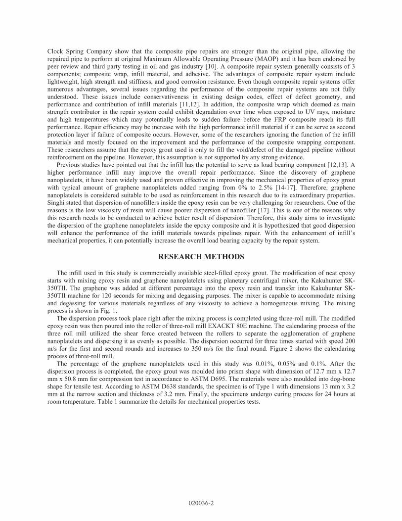
The dispersion process took place right after the mixing process is completed using three-roll mill. The modified epoxy resin was then poured into the roller of three-roll mill EXACKT 80E machine. The calendaring process of the three roll mill utilized the shear force created between the rollers to separate the agglomeration of graphene nanoplatelets and dispersing it as evenly as possible. The dispersion occurred for three times started with speed 200 m/s for the first and second rounds and increases to 350 m/s for the final round. Figure 2 shows the calendaring process of three-roll mill.
The percentage of the graphene nanoplatelets used in this study was 0.01%, 0.05% and 0.1%. After the dispersion process is completed, the epoxy grout was moulded into prism shape with dimension of 12.7 mm x 12.7 mm x 50.8 mm for compression test in accordance to ASTM D695. The materials were also moulded into dog-bone shape for tensile test. According to ASTM D638 standards, the specimen is of Type 1 with dimensions 13 mm x 3.2 mm at the narrow section and thickness of 3.2 mm. Finally, the specimens undergo curing process for 24 hours at room temperature. Table 1 summarize the details for mechanical properties tests.
020036-2
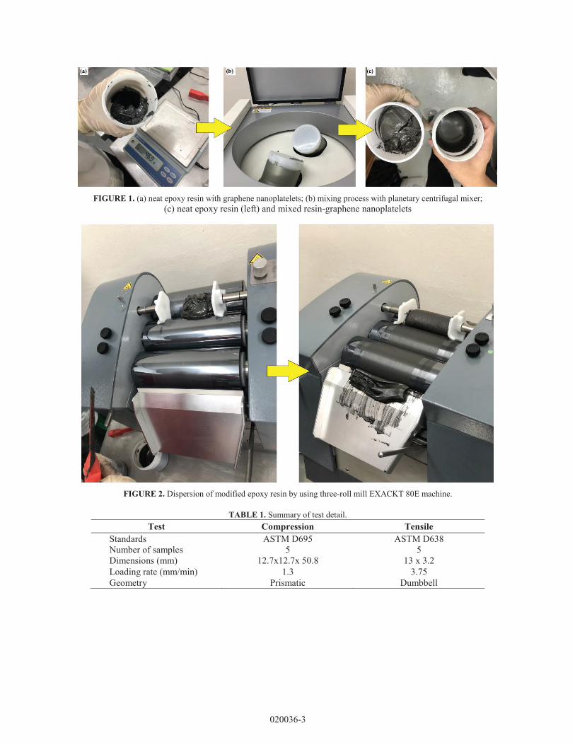
FIGURE 1. (a) neat epoxy resin with graphene nanoplatelets; (b) mixing process with planetary centrifugal mixer;(c) neat epoxy resin (left) and mixed resin-graphene nanoplatelets
FIGURE 2. Dispersion of modified epoxy resin by using three-roll mill EXACKT 80E machine.
TABLE 1. Summary of test detail.Test Compression Tensile
Standards ASTM D695 ASTM D638Number of samples 5 5Dimensions (mm) 12.7x12.7x 50.8 13 x 3.2Loading rate (mm/min) 1.3 3.75Geometry Prismatic Dumbbell
020036-3
RESULTS AND DISCUSSION
Mechanical Properties of Modified Epoxy Grout
The results of tensile and compressive strength for all tested grouts are summarized in Table 2. The plus and minus sign (±) after the average value represents standard deviation of the sample. Five specimens of modified graphene were studied under tensile test and compression test. The strength values presented in the table are the average of the maximum stress of 5 specimens when the failure of specimen occurred. Infill with high tensilestrength may potentially increase the overall load bearing capacity while high compressive strength is important to aid for load transfer from defective pipe to composite wrap.
The tensile strength was observed to be ranged between 13 MPa to 20 MPa for tensile test and 67 MPa to 82 MPa for compressive test, respectively. As shown in Table 2, the tensile strength increase as the percentage of graphene nanoplatelets added into the epoxy resin increases. When comparing with the control specimen, the tensile strength of modified epoxy grouts shows increment of 23%, 38% and 50% for 0.01%, 0.05% and .01% of graphene added, respectively. On the other hand, under compressive test, the modified epoxy grout has ability to increase the compressive strength in all samples. The highest compressive strength is recorded at 82.67 MPa which is sample with 0.05% graphene added to the epoxy grout. There is a 22% of strength increment as compared to control samples. The compressive strength of 0.1% and 0.01% graphene also shows 9% and 20% increment when comparing with control sample, respectively. This shows that the optimum percentage for the compressive strength improvement is 0.05% for the tested graphene percentage.
TABLE 2. Tensile and compressive strength.Epoxy Grout Tensile Strength (MPa) Compressive Strength (MPa)
Control sample 13.12 ± 4.95 67.08 ± 10.240.01% of graphene 16.22 ± 8.18 80.80 ± 5.100.05% of graphene 18.18 ± 1.38 82.67 ± 6.830.1% of graphene 20.89 ± 8.09 73.02 ± 11.61
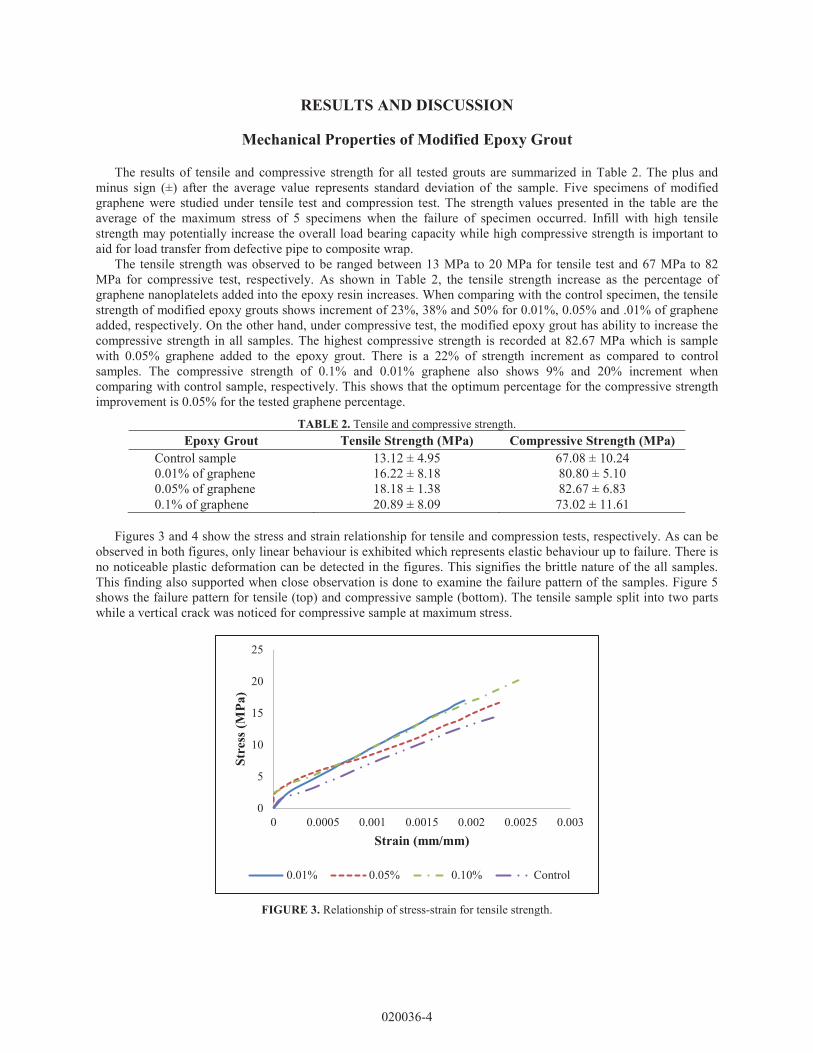
Figures 3 and 4 show the stress and strain relationship for tensile and compression tests, respectively. As can be observed in both figures, only linear behaviour is exhibited which represents elastic behaviour up to failure. There is no noticeable plastic deformation can be detected in the figures. This signifies the brittle nature of the all samples. This finding also supported when close observation is done to examine the failure pattern of the samples. Figure 5 shows the failure pattern for tensile (top) and compressive sample (bottom). The tensile sample split into two parts while a vertical crack was noticed for compressive sample at maximum stress.
FIGURE 3. Relationship of stress-strain for tensile strength.
0
5
10
15
20
25
0 0.0005 0.001 0.0015 0.002 0.0025 0.003
Stre
ss (M
Pa)
Strain (mm/mm)
0.01% 0.05% 0.10% Control
020036-4

FIGURE 4. Relationship of stress-strain for compressive strength.
FIGURE 5. Failure pattern of tensile (top) and compression (bottom) specimen.
Morphology of Modified Epoxy Grout
FESEM results of all epoxy grouts are presented in Fig. 6. The FESEM test was conducted to study the failure surface of selected tensile samples. As shown in Fig. 6, abundant of graphene nanoplatelets particles can be seen on the failure surface of 0.1% graphene specimen while only few graphene particles was detected on the failure surface for 0.01% sample. This indicates that the amount of graphene may still not up to the maximum quantity as reinforcement for the epoxy grout in tensile specimen. Based on the findings of tensile test and supported by FESEM result, a higher percentage of graphene has the potential to further increase the tensile strength.
0102030405060708090
0 0.002 0.004 0.006 0.008 0.01 0.012
Stre
ss (M
Pa)
Strain (mm/mm)
0.01% 0.05% 0.10% Control
020036-5
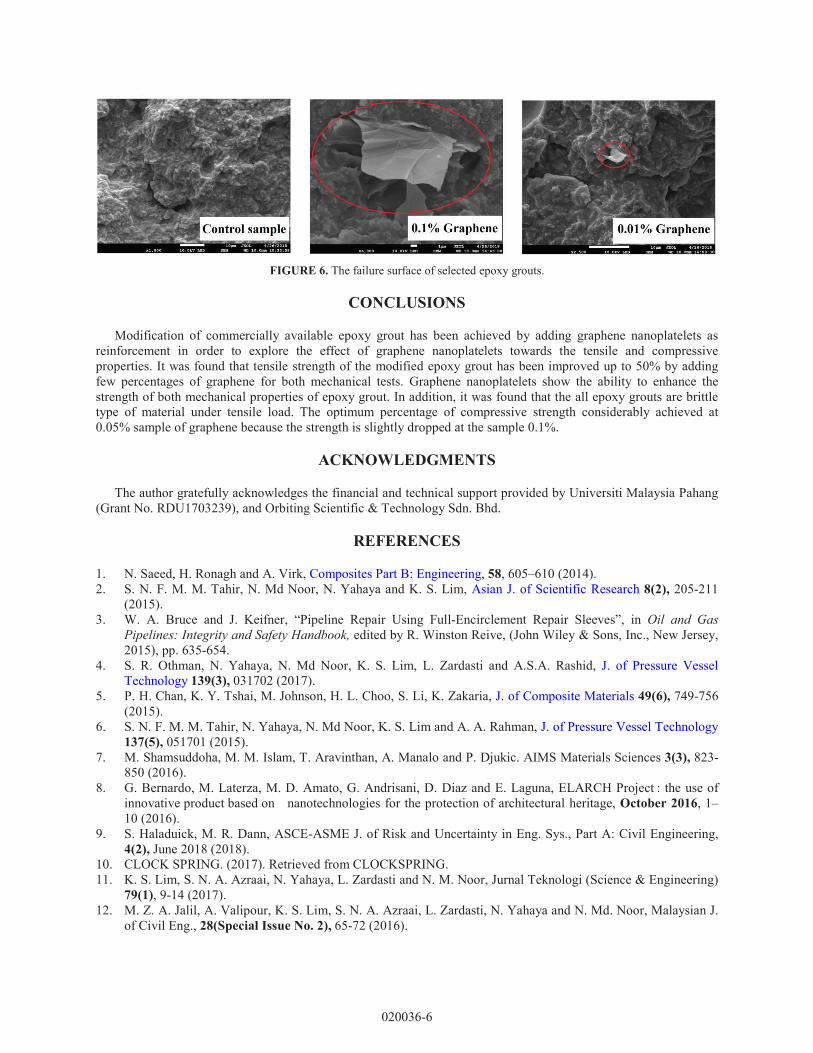
FIGURE 6. The failure surface of selected epoxy grouts.
CONCLUSIONS
Modification of commercially available epoxy grout has been achieved by adding graphene nanoplatelets asreinforcement in order to explore the effect of graphene nanoplatelets towards the tensile and compressive properties. It was found that tensile strength of the modified epoxy grout has been improved up to 50% by addingfew percentages of graphene for both mechanical tests. Graphene nanoplatelets show the ability to enhance the strength of both mechanical properties of epoxy grout. In addition, it was found that the all epoxy grouts are brittle type of material under tensile load. The optimum percentage of compressive strength considerably achieved at 0.05% sample of graphene because the strength is slightly dropped at the sample 0.1%.
ACKNOWLEDGMENTS
The author gratefully acknowledges the financial and technical support provided by Universiti Malaysia Pahang (Grant No. RDU1703239), and Orbiting Scientific & Technology Sdn. Bhd.
REFERENCES
1. N. Saeed, H. Ronagh and A. Virk, Composites Part B: Engineering, 58, 605–610 (2014).2. S. N. F. M. M. Tahir, N. Md Noor, N. Yahaya and K. S. Lim, Asian J. of Scientific Research 8(2), 205-211
(2015).3. W. A. Bruce and J. Keifner, “Pipeline Repair Using Full-Encirclement Repair Sleeves”, in Oil and Gas
Pipelines: Integrity and Safety Handbook, edited by R. Winston Reive, (John Wiley & Sons, Inc., New Jersey,2015), pp. 635-654.
4. S. R. Othman, N. Yahaya, N. Md Noor, K. S. Lim, L. Zardasti and A.S.A. Rashid, J. of Pressure Vessel Technology 139(3), 031702 (2017).
5. P. H. Chan, K. Y. Tshai, M. Johnson, H. L. Choo, S. Li, K. Zakaria, J. of Composite Materials 49(6), 749-756 (2015).
6. S. N. F. M. M. Tahir, N. Yahaya, N. Md Noor, K. S. Lim and A. A. Rahman, J. of Pressure Vessel Technology 137(5), 051701 (2015).
7. M. Shamsuddoha, M. M. Islam, T. Aravinthan, A. Manalo and P. Djukic. AIMS Materials Sciences 3(3), 823-850 (2016).
8. G. Bernardo, M. Laterza, M. D. Amato, G. Andrisani, D. Diaz and E.innovative product based on nanotechnologies for the protection of architectural heritage, October 2016, 1–10 (2016).
9. S. Haladuick, M. R. Dann, ASCE-ASME J. of Risk and Uncertainty in Eng. Sys., Part A: Civil Engineering, 4(2), June 2018 (2018).
10. CLOCK SPRING. (2017). Retrieved from CLOCKSPRING.11. K. S. Lim, S. N. A. Azraai, N. Yahaya, L. Zardasti and N. M. Noor, Jurnal Teknologi (Science & Engineering)
79(1), 9-14 (2017).12. M. Z. A. Jalil, A. Valipour, K. S. Lim, S. N. A. Azraai, L. Zardasti, N. Yahaya and N. Md. Noor, Malaysian J.
of Civil Eng., 28(Special Issue No. 2), 65-72 (2016).
020036-6

13. I. Chebakov and Gh. Dumitru, “Finite Element Stress Analysis of Pipelines with Advanced Composite Repair”, in Non-destructive Testing and Repair of Pipelines, Engineering Materials,edited by E.N. Barkanov et al., (Springer International Publishing, Switzerland, 2018), pp. 289-309.
14. S. Chatterjee, F. Nafazarefi, N. H. Tai, L. Schlagenhauf and B. T. T. Chu, Carbon 50, 5380-5386 (2012).15. L. C. Tang, Y. J. Wan, D. Yan, Y. B. Pei, L. Zhao, Y. B. Li and G. Q. Lai, Carbon 60, 16-27 (2013).16. R. Atif, I. Shyha and F. Inam, Polymers 8(281), 1-37 (2016).17. M. Singhi, Int. J. of Sci. Technology and Management 4(Special Issue 1), 425–432 (2015).
020036-7
![Synthesis and properties of bulk graphene nanoplatelets ...web.eng.fiu.edu/agarwala/PDF/2012/2.pdf · graphene or carbon nanotubes [18]. One of the major chal-lenges in composite](https://img.pdfslide.net/doc/110x75/5f9d3a013fe4347003703edd/synthesis-and-properties-of-bulk-graphene-nanoplatelets-webengfiueduagarwalapdf20122pdf.jpg)


![Free-standing graphene films embedded in epoxy resin with enhanced thermal … · 2020-03-21 · ofthe pure epoxy resin.Yi Wang [8] outlined that the thermal conductivity of the epoxy](https://img.pdfslide.net/doc/110x75/5fb4caffabd6f51d5367cfc5/free-standing-graphene-films-embedded-in-epoxy-resin-with-enhanced-thermal-2020-03-21.jpg)