Embed Size (px)
Citation preview
Effectiveness and Accuracy of Wireless Positioning Systems
SEBASTIAN FUICU*, MARIUS MARCU
*, BOGDAN STRATULAT
*, ANANIA GIRBAN
**
*Computer Science and Engineering Department
**Mathematics Department
“Politehnica” University of Timisoara
Timisoara, Bd. V. Parvan, No. 2
ROMANIA
[email protected], [email protected], [email protected], [email protected]
Abstract: - Localization or positioning is an important aspect of mobile applications in order to achieve context-
aware applications. The main goal for localization process is estimating the position of a mobile device in its
environment based on a set of sensors with known positions. Modern mobile devices produced nowadays, and
almost all smartphones and PDAs, have one or more wireless communication interfaces in order to
communicate with other devices. WLAN infrastructure is a widely accepted and implemented communication
standard in many indoor environment, therefore many buildings are already equipped with IEEE 802.11
WLAN infrastructure access points. Wireless adapters the modern mobile devices are equipped with can
monitor radio power strength of the emitting sources nearby. Based on the received radio signal strength an
estimation of distance between the device and power source can be computed. In this paper we want to describe
and conclude our work regarding the possibility to design a simple and energy efficient positioning solution to
be implemented on mobile devices with limited resources.
Key-Words: - wireless positioning systems, radio signal strength, energy efficiency, trilateration
1 Introduction One of the most significant elements of context-
awareness in ubiquitous environments is mobile
device localization. To obtain the accurate location
information for indoor environments is a
challenging problem; therefore there have been a
number of attempts to design systems for indoor
localization using different wireless sensing
techniques. Signal strength (SS) approaches are easy
to implement in the existing technologies in mobile
devices. We want to investigate the positioning
methods based on the trilateration scheme with a
simply and clearly mathematical model.
Localization or positioning is an important aspect
of mobile applications in order to achieve context-
aware applications. The main goal for localization
process is estimating the position of a mobile device
in its environment based on a set of sensors with
known positions. Modern mobile devices produced
nowadays, and almost all smartphones and PDAs,
have one or more wireless communication
interfaces, like bluetooth or WiFi, in order to
communicate with infrastructure computing systems
or other mobile devices. WLAN infrastructure is a
widely accepted and implemented communication
standard in many indoor environment, therefore
many buildings are already equipped with IEEE
802.11 WLAN infrastructure access points [1].
Wireless adapters the modern mobile devices are
equipped with can monitor radio power strength of
the emitting sources nearby. Based on the received
radio signal strength an estimation of distance
between the device and power source can be
computed. If a mobile device can monitor at least
three WLAN power signal sources with a-priori
known positions, an estimation of the mobile device
position can be achieved. This approach has the
advantage that no costly hardware installations are
necessary inside the building, nor additional sensors
to be attached with the mobile devices [2].
Many mobile applications would benefit from
being able to use WLAN for communication as well
as positioning [1]. Determining the physical location
of mobile active indoor nodes, can be one of the
main issues of a new class of applications and
position-dependent services in ubiquitous systems.
For example only localization applications for
ubiquitous systems will have a growth of value (8
times in 5 years) from 1 billion USD in 2005 up to
8.5 billion USD in 2010 [3]. Hence we can say that
we shall face with a pronounced development of the
number of applications that run on such devices and
use different positioning techniques.
WSEAS TRANSACTIONS on COMPUTERS Sebastian Fuicu, Marius Marcu, Bogdan Stratulat, Anania Girban
ISSN: 1109-2750 1471 Issue 9, Volume 8, September 2009
The goal of this paper is to evaluate the
possibility to implement a simple wireless
positioning systems using only trilateration. The
main requirement in developing such a software
solution is low computational power resources
usage and the second one is to have minimum
impact on power consumption.
This paper is structures as follows: in next
section the related works on positioning systems are
presented. The proposed mathematical model
variants are described in section 3. The framework
architecture for wireless positioning is described
briefly in section 4. The experimental test cases and
their results are presented in section 5. Finally we
conclude the paper in section 6.
2 Related Work In the literature there are many approaches for
designing methods for positioning systems,
which are different in terms of distance
measurement techniques and mathematical
models.
There are a few different localization methods
that can be used for the positioning procedure.
These methods are divided into three major
categories based on the environment in which the
information is spread: indoor, outdoor or mixed.
Positioning systems consist of algorithms and
methods to estimate the position of an unknown
target, and are classified based on [4]:
- the signal types:
o infrared,
o ultrasound,
o ultra-wideband, and
o radio frequency
- the signal metrics
o global location systems - outdoor methods
o cellular location systems - mixed methods
o indoor location systems.
The most popular outdoor localization system is
known as GPS (global positioning system). The
GPS receiver calculates its current position
(longitude, latitude, elevation) using a trilateration
technique. The distance is computed based on the
time delay between the transmission and reception
of the encrypted radio signal issued by the satellites.
In comparison with these systems, the indoor
system poses additional challenges. In our work we
address the indoor positioning problem. Different
techniques exist for estimating the position of a
mobile device in a wireless network [1]:
- cell based - with this localization technique the
position of a device is simply located around
the position of the access point where the
device is connected.
- signal propagation time based - the position is
determied using the time of arrival of the
receved signal from several access points (APs)
to the target device.
- signal angle of arrival - the position of a device
could be estimated based on the measured
angle of arrival of received signal from
surrounding APs.
- receiver signal strength based - the position of a
target device is estimated using the received
signal strength from surrounding APs.
Cell based positioning method is very simple and
considers that a mobile device is located near the
known position of the AP this device is connected
to. Despite its simplicity this method is not largely
used because of the lack of accuracy.
The propagation time can be directly translated
into distance, based on the known signal
propagation speed [5]. Based on signal propagation
time from surrounding APs to the target device, its
position can be estimated. These techniques offer
increased accuracy but they require precise clock
synchronization and more expensive infrastructure.
There are two important methods in this category:
ToA (Time of Arrival) [6] and TDoA (Time
Difference of Arrival) [7]. The most important
parameter for accurate indoor positioning systems is
the time of arrival TOA of the Direct Line of Sight
path [8]. Therefore an accurate estimation of TOA
from received communication signals is required.
Angle measurements can be used for indoor
positioning using AoA (Angle of Arrival) of the
received signal or DoA (Dirrection of Arrival) [9,
10]. For this technique additional hardware is also
needed in order to measure the angle of incidence of
the received signal. The AOA requires antenna
arrays at each node which increase the complexity
of the existing system, as well as, performing worse
in multipath environment [7].
The fourth solutions class for indoor positioning
system is based on received radio signal strength of
the surrounding APs. This positioning method uses
the existing WLAN infrastructure and does not need
any extra hardware attached to the target device.
The network card in the mobile device continuously
measures the RSSI (Radio Signal Strength
Indicator) of the APs in its neighbor. This
information is available due to beacon broadcast
multiple times per second by every AP [2]. Based
WSEAS TRANSACTIONS on COMPUTERS Sebastian Fuicu, Marius Marcu, Bogdan Stratulat, Anania Girban
ISSN: 1109-2750 1472 Issue 9, Volume 8, September 2009
on RSSI the mobile device can estimate the distance
from its position to the AP it measured the RSSI.
Using at least three APs with well known positions,
a mobile device can estimate its position based on
measured RSSI from these APs.
RSS based WPS (Wireless Positioning Systems)
were studied a lot in the last years. There are at least
three location algorithms in this class of WPS:
- fingerprinting (RSS patterns [2, 11, 12])
- simulation (lines of constant RSS [1, 13])
- trilateration (Euclidian distance extracted from
RSS [14])
The fingerprinting method is the most common
used for WPS. An estimate of the target device
position is obtained from the RSSI measurements
and using a radio signal propagation model inside
the building [2]. The propagation model can be
obtained using a priori RSS measurements in
different locations in the building. These
measurements compose a RSS map, called
fingerprint, are stored in a database and can further
be used to estimate the position of a target device.
This method is divided in two phases [1]: initial
calibration phase where the RSS map is achieved
and the positioning phase, the measured RSS values
from surrounding APs are compared to the ones
stored in the database in order to estimate the
current position of the device. The disadvantages of
this approach are the database generation and
maintenance requirements [11]. During the WPS
lifetime, every change in the infrastructure requires
the build of the RSS map.
The second class of WPS methods uses
simulation algorithms to build the propagation
models of the radio signal inside the building. The
simulation starts from the building map and
positions of APs on the map. During the simulation
for every AP the lines of constant RSS, called
isobars, are computed. After the simulation the map
of RSS isobars for every AP is obtained. This map
can be further used by a mobile device to estimate
its position inside the building. The drawbacks of
this method are the complexity of the propagation
model simulator and the computation resources
needed to run the simulation algorithms.
A network-based localization method is
presented in [15], which uses the radio propagation
signal strength that covers a 2D plane, where three
sniffers are placed in order to listen to a single
signal strength emitted by the mobile and to
automatically generate an estimated signal strength
map. Also, the algorithm is able to establish the
mobile’s position by browsing this table.
Unlike the previously described method a client-
based localization solution is presented in [16],
using radio-frequency (RF) as well, in which the
main element is recording and processing the
signals received from several base stations that are
placed by overlapping coverage in the 2D plane.
The triangulation is achieved by using two methods:
the first one requires measuring the signals and
creating a signal strength map SS-MAP and
searching the best signal strength measurements; the
second method requires the usage of a simple
propagation model in order to estimate the SS-MAP.
The authors of [2] developed and tested a
software framework called “ipos” for indoor
positioning based on WLAN fingerprinting the can
by used to build location based applications. It
consists of an efficient, freely configurable
framework, which is suitable for multiple
application architectures. The RSS measurements
are performed on the mobile device, the
computation and visualization of position can be run
on an infrastructure server or on the device itself.
Based on their tests they obtained and accuracy of
better than 3 meters for an area of 1500 m2 covered
by 7 APs.
The authors of [1] developed a method to
identify intersections of lines of constant RSSI
values, called isolines, of several APs within
interpolated radio maps based on triangulation.
Based on their tests an average deviation of 3 meters
was obtained for 330 m2 exhibition room equiped
with 4 APs.
The aim of the work presented in paper [17] is to
study the possibilities that the WLAN's offer to
indoor localization and to implement an application
that will help to localize a device equipped with a
WLAN's card supporting the IEEE 802.1lb protocol.
The application developed by the authors called
Wlib uses a database with signal strength values
stored and a mathematical model in order to
estimate the position of a user with a wireless device
into a library of their University.
The third RSS method is based on trilateration
[14]. This approach is simple, easy to implement
and needs fewer resources to compute the position.
This method is appropriate for a mobile device
where the energy and computational resources are
limited, even the accuracy of the method is in the
best case comparable with the other methods.
The disadvantage of all RSS methods is the
random deviation from mean received signal
strength caused by shadowing and small scale
WSEAS TRANSACTIONS on COMPUTERS Sebastian Fuicu, Marius Marcu, Bogdan Stratulat, Anania Girban
ISSN: 1109-2750 1473 Issue 9, Volume 8, September 2009
channel effect [7]. We consider based on our tests,
that the accuracies obtained by other positioning
applications are the best that can be achieved and in
the real life usage scenarios the positioning accuracy
will decrease significantly due to: changes in the
environment, people moving around in the
measured environment, mobile device speed and
orientation, APs radio signal transmitter’s
fluctuations, etc.
Power consumption and energy efficiency are an
important aspect for mobile applications in general
and for local positioning application in special.
Therefore one of the topics we investigate in this
paper is the energy efficiency of WPS applications.
The power consumption problem of mobile systems
is in general a very complex one and remained of
interest for quite a long time [18, 19]. In this paper
defined a software execution framework for mobile
systems in order to characterize the power
consumption profile of different types of mobile
applications [18].
Our goal is to investigate how trilateration can be
used in indoor positioning, to estimate its accuracy
and its needed resources for the mobile devices. We
target positioning in large rooms with different
objects inside the room and people moving inside
the room. We also want to be realistic and provide
also the problems such a positioning system
implementation will face during its exploitation.
This paper covers our work in last three years
partially presented in some conference papers [14,
20, 21, and 22].
3 Mathematical model The trilateration assumes the existence of at least
three access points (APs) with known positions. The
distance between each access point (AP) and the
mobile device (MD) have to be determined by
computations. For every distance a circle can be
drawn. In the ideal case, these three circles must
intersect in a single point which is actually the
position of our mobile device (MD).
The method chosen for obtaining the distance
between AP and MS is based on the signal strength
(SS) measurement [22]. The propagation of radio
waves is influenced by three factors: “free space
loss”, attenuation by the objects on the propagation
path, and the signal’s scattering. In the absence of
obstacles, the model for propagation is “free space
loss” which can be expressed for the ideal isotropic
antenna as in (1):
( ) ( )
2
2
2
44
c
dfd
P
P
r
t π
λ
π==
(1)
Pt – signal power at the emitter
Pr – signal power at the receiver
d – propagation distance between emitter and
receiver
λ - carrier wavelength
f – carrier frequency
c – speed of light
The ideal situation, when there’s no obstacle, we
consider the bi-dimensional case when all APs and
the mobile device are in the same plan. If no
perturbations interfered along the measuring, at
moment t, M receives a signal with Pi power from
the transmitter APi. The distance between M and
APi could be calculated with the formula (2):
=
f
c
P
Pd
ri
it
iπ4
(2)
In the real world, measuring SS is made with
some errors, because the SS cannot be determined
with very high precision, even in the case of
obstacle absence. If we take into account the
attenuation induced by some obstacles the problem
could be more complicated. Hence the intersection
of the three circles is not a single point. For three
access points the maximum number of points is six,
because every two circles can generate two points of
intersection.
The ideal situation, when there’s no obstacle, we
consider a bi-dimensional case. If no perturbations
interfered along the measuring, at the t moment, M
receive P1, P2 and P3 from the 3 transmitters AP1,
AP2, AP3 respectively. So, it is at:
=
f
c
P
Pd
r
t
π41
11
(3)
from the transmitter AP1,
=
f
c
P
Pd
r
t
π42
22
(4)
from the transmitter AP2,
=
f
c
P
Pd
r
t
π43
33
(5)
from the transmitter AP3,
WSEAS TRANSACTIONS on COMPUTERS Sebastian Fuicu, Marius Marcu, Bogdan Stratulat, Anania Girban
ISSN: 1109-2750 1474 Issue 9, Volume 8, September 2009
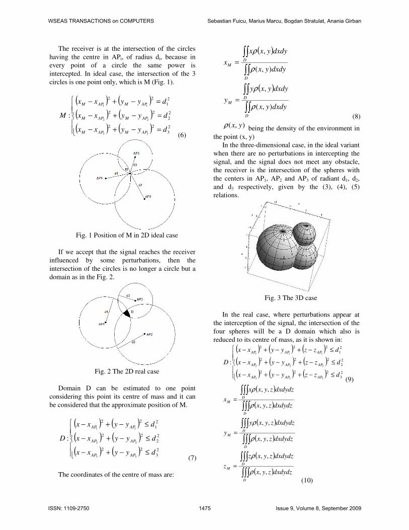
The receiver is at the intersection of the circles
having the centre in APi, of radius di, because in
every point of a circle the same power is
intercepted. In ideal case, the intersection of the 3
circles is one point only, which is M (Fig. 1).
( ) ( )
( ) ( )
( ) ( )
=−+−
=−+−
=−+−
2
3
22
2
2
22
2
1
22
33
22
11
:
dyyxx
dyyxx
dyyxx
M
APMAPM
APMAPM
APMAPM
(6)
Fig. 1 Position of M in 2D ideal case
If we accept that the signal reaches the receiver
influenced by some perturbations, then the
intersection of the circles is no longer a circle but a
domain as in the Fig. 2.
Fig. 2 The 2D real case
Domain D can be estimated to one point
considering this point its centre of mass and it can
be considered that the approximate position of M.
( ) ( )
( ) ( )
( ) ( )
≤−+−
≤−+−
≤−+−
2
3
22
2
2
22
2
1
22
33
22
11
:
dyyxx
dyyxx
dyyxx
D
APAP
APAP
APAP
(7)
The coordinates of the centre of mass are:
( )
( )
∫∫
∫∫
∫∫
∫∫
=
=
D
D
M
D
D
M
dxdyyx
dxdyyxy
y
dxdyyx
dxdyyxx
x
),(
,
),(
,
ρ
ρ
ρ
ρ
(8)
),( yxρ being the density of the environment in
the point (x, y)
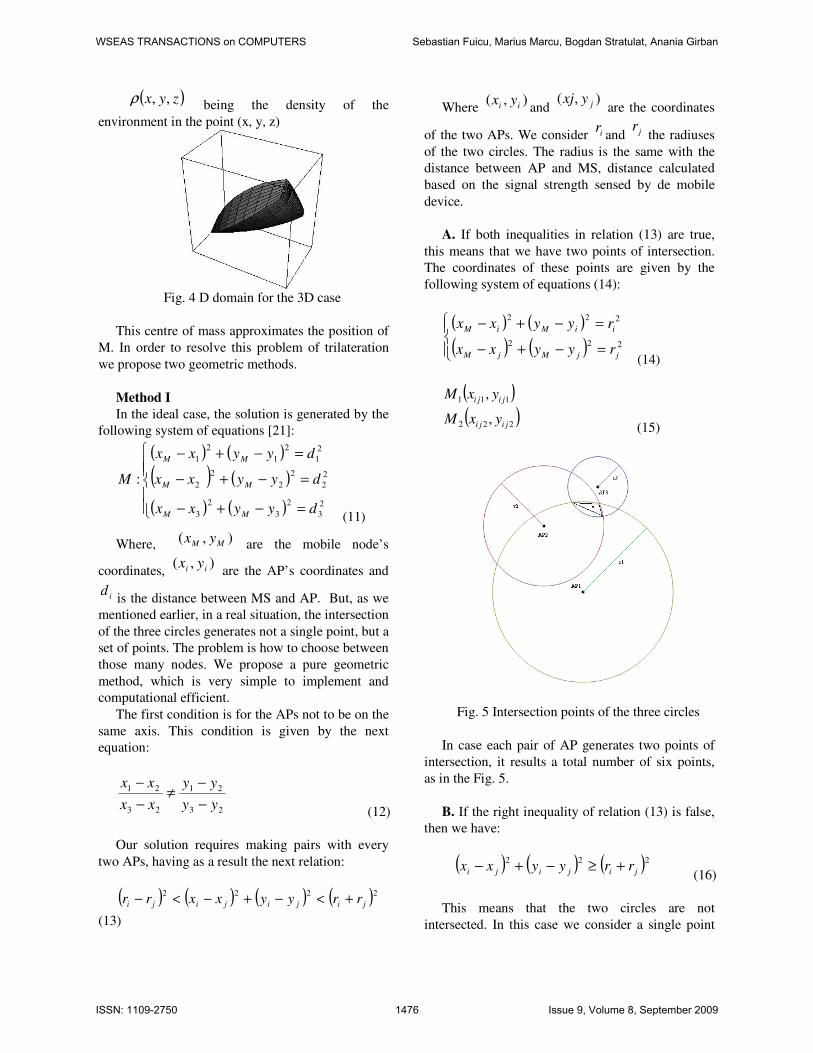
In the three-dimensional case, in the ideal variant
when there are no perturbations in intercepting the
signal, and the signal does not meet any obstacle,
the receiver is the intersection of the spheres with
the centers in AP1, AP2 and AP3 of radiant d1, d2,
and d3 respectively, given by the (3), (4), (5)
relations.
Fig. 3 The 3D case
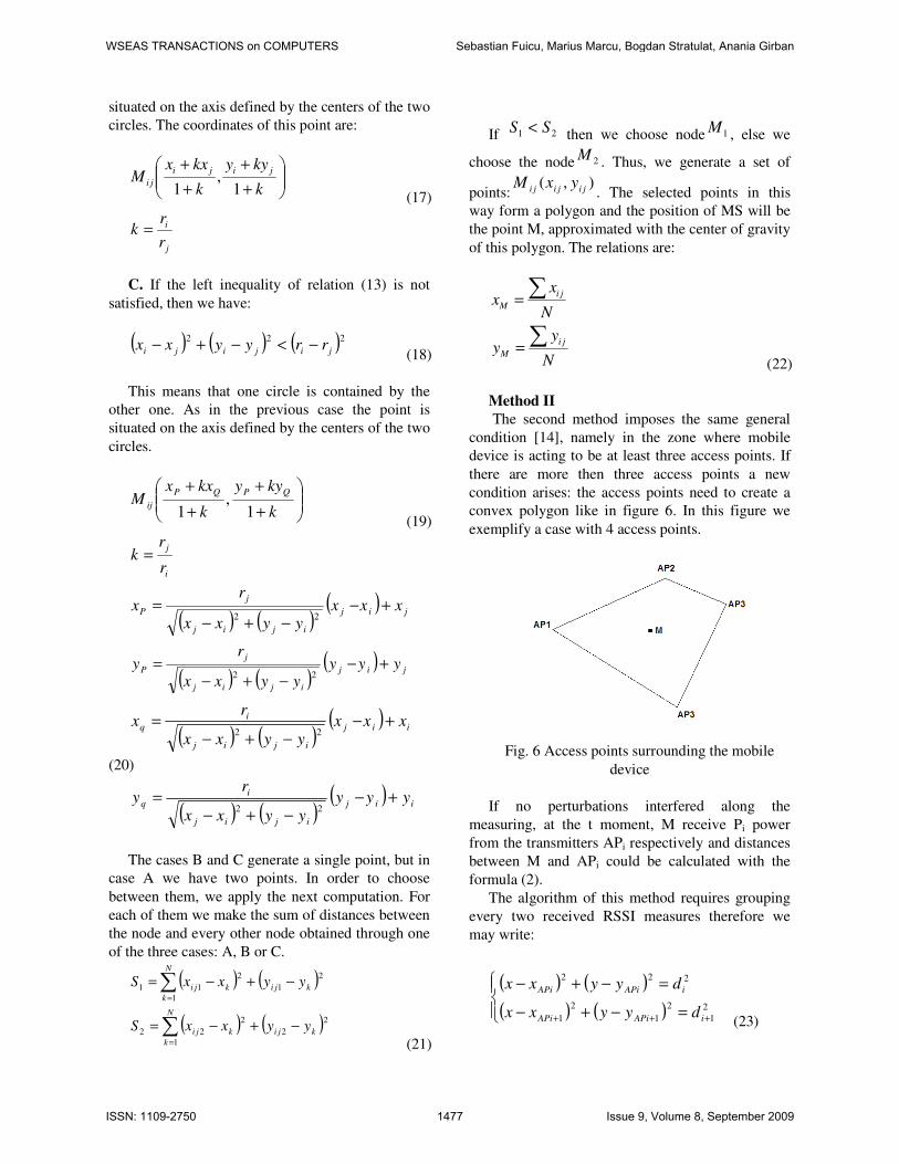
In the real case, where perturbations appear at
the interception of the signal, the intersection of the
four spheres will be a D domain which also is
reduced to its centre of mass, as it is shown in:
( ) ( ) ( )
( ) ( ) ( )
( ) ( ) ( )
≤−+−+−
≤−+−+−
≤−+−+−
2
3
222
2
2
222
2
1
222
333
222
111
:
dzzyyxx
dzzyyxx
dzzyyxx
D
APAPAP
APAPAP
APAPAP
(9)
( )
( )
( )
( )
( )
( )∫∫∫
∫∫∫
∫∫∫
∫∫∫
∫∫∫
∫∫∫
=
=
=
D
D
M
D
DM
D
D
M
dxdydzzyx
dxdydzzyxz
z
dxdydzzyx
dxdydzzyxy
y
dxdydzzyx
dxdydzzyxx
x
,,
,,
,,
,,
,,
,,
ρ
ρ
ρ
ρ
ρ
ρ
(10)
WSEAS TRANSACTIONS on COMPUTERS Sebastian Fuicu, Marius Marcu, Bogdan Stratulat, Anania Girban
ISSN: 1109-2750 1475 Issue 9, Volume 8, September 2009
( )zyx ,,ρ being the density of the
environment in the point (x, y, z)
Fig. 4 D domain for the 3D case
This centre of mass approximates the position of
M. In order to resolve this problem of trilateration
we propose two geometric methods.
Method I
In the ideal case, the solution is generated by the
following system of equations [21]:
( ) ( )
( ) ( )
( ) ( )
=−+−
=−+−
=−+−
2
3
2
3
2
3
2
2
2
2
2
2
2
1
2
1
2
1
:
dyyxx
dyyxx
dyyxx
M
MM
MM
MM
(11)
Where, ),( MM yx are the mobile node’s
coordinates, ),( ii yx
are the AP’s coordinates and
idis the distance between MS and AP. But, as we
mentioned earlier, in a real situation, the intersection
of the three circles generates not a single point, but a
set of points. The problem is how to choose between
those many nodes. We propose a pure geometric
method, which is very simple to implement and
computational efficient.
The first condition is for the APs not to be on the
same axis. This condition is given by the next
equation:
23
21
23
21
yy
yy
xx
xx
−
−≠
−
−
(12)
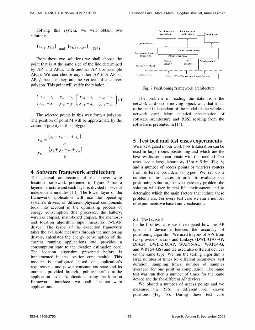
Our solution requires making pairs with every
two APs, having as a result the next relation:
( ) ( ) ( ) ( )2222
jijijiji rryyxxrr +<−+−<−
(13)
Where ),( ii yx
and ),( jyxj
are the coordinates
of the two APs. We consider ir and jr the radiuses
of the two circles. The radius is the same with the
distance between AP and MS, distance calculated
based on the signal strength sensed by de mobile
device.
A. If both inequalities in relation (13) are true,
this means that we have two points of intersection.
The coordinates of these points are given by the
following system of equations (14):
( ) ( )
( ) ( )
=−+−
=−+−
222
222
jjMjM
iiMiM
ryyxx
ryyxx
(14)
( )
( )222
111
,
,
jiji
jiji
yxM
yxM
(15)
Fig. 5 Intersection points of the three circles
In case each pair of AP generates two points of
intersection, it results a total number of six points,
as in the Fig. 5.
B. If the right inequality of relation (13) is false,
then we have:
( ) ( ) ( )222
jijiji rryyxx +≥−+− (16)
This means that the two circles are not
intersected. In this case we consider a single point
WSEAS TRANSACTIONS on COMPUTERS Sebastian Fuicu, Marius Marcu, Bogdan Stratulat, Anania Girban
ISSN: 1109-2750 1476 Issue 9, Volume 8, September 2009
situated on the axis defined by the centers of the two
circles. The coordinates of this point are:
+
+
+
+
k
kyy
k
kxxM
jiji
ji1
,1
(17)
j
i
r
rk =
C. If the left inequality of relation (13) is not
satisfied, then we have:
( ) ( ) ( )222
jijiji rryyxx −<−+− (18)
This means that one circle is contained by the
other one. As in the previous case the point is
situated on the axis defined by the centers of the two
circles.
+
+
+
+
k
kyy
k
kxxM
QPQP
ij1
,1
(19)
i
j
r
rk =
( ) ( )
( )jij
ijij
j
P xxxyyxx
rx +−
−+−
=22
( ) ( )
( )jij
ijij
j
P yyyyyxx
ry +−
−+−
=22
( ) ( )
( )iij
ijij
i
q xxxyyxx
rx +−
−+−
=22
(20)
( ) ( )
( )iij
ijij
i
q yyyyyxx
ry +−
−+−
=22
The cases B and C generate a single point, but in
case A we have two points. In order to choose
between them, we apply the next computation. For
each of them we make the sum of distances between
the node and every other node obtained through one
of the three cases: A, B or C.
( ) ( )
( ) ( )∑
∑
=
=
−+−=
−+−=
N
k
kjikji
N
k
kjikji
yyxxS
yyxxS
1
2
2
2
22
1
2
1
2
11
(21)
If 21 SS < then we choose node 1M , else we
choose the node 2M . Thus, we generate a set of
points:),( jijiji yxM
. The selected points in this
way form a polygon and the position of MS will be
the point M, approximated with the center of gravity
of this polygon. The relations are:
N
yy
N
xx
ji
M
ji
M
∑
∑
=
=
(22)
Method II
The second method imposes the same general
condition [14], namely in the zone where mobile
device is acting to be at least three access points. If
there are more then three access points a new
condition arises: the access points need to create a
convex polygon like in figure 6. In this figure we
exemplify a case with 4 access points.
Fig. 6 Access points surrounding the mobile
device
If no perturbations interfered along the
measuring, at the t moment, M receive Pi power
from the transmitters APi respectively and distances
between M and APi could be calculated with the
formula (2).
The algorithm of this method requires grouping
every two received RSSI measures therefore we
may write:
( ) ( )
( ) ( )
=−+−
=−+−
+++
2
1
2
1
2
1
222
iAPiAPi
iAPiAPi
dyyxx
dyyxx
(23)
WSEAS TRANSACTIONS on COMPUTERS Sebastian Fuicu, Marius Marcu, Bogdan Stratulat, Anania Girban
ISSN: 1109-2750 1477 Issue 9, Volume 8, September 2009
Solving this system, we will obtain two
solutions:
( )11 , MM yx and ( )22 , MM yx (24)
From these two solutions we shall choose the
point that is at the same side of the line determined
by APi and APi+1, with another AP (for example
APi-1). We can choose any other AP (not APi or
APi+1) because they are the vertices of a convex
polygon. This point will verify the relation:
01
1
1
1
11
>
−
−−
−
−
−
−−
−
−
+
−
+
−
++ ii
ii
ii
ii
ii
iM
ii
iM
yy
yy
xx
xx
yy
yy
xx
xx
The selected points in this way form a polygon.
The position of point M will be approximate by the
center of gravity of this polygon.
( )
n
xxxx n
M
+++=
...21
( )
n
yyyy n
M
+++=
...21
4 Software framework architecture The general architecture of the power-aware
location framework presented in figure 7 has a
layered structure and each layer is divided in several
independent modules [14]. The lower layer of the
framework application will use the operating
system’s drivers of different physical components
took into account in the optimizing process of
energy consumption (the processor, the battery,
wireless chipset, main-board chipset, the memory)
and location algorithm input measures (WLAN
driver). The kernel of the execution framework
takes the available measures through the monitoring
drivers, calculates the energy consumption of the
current running applications and provides a
consumption state to the location estimation core.
The location algorithm presented before is
implemented in the location core module. This
module is configured based on application’s
requirements and power consumption state and its
output is provided through a public interface to the
application level. Applications using the location
framework interface we call location-aware
applications.
Fig. 7 Positioning framework architecture
The problem in reading the data from the
network card on the moving object, was, that it has
to be read independent of the model of the wireless
network card. More detailed presentation of
software architecture and RSSI reading from the
software is presented in [14].
5 Test bed and test cases experiments We investigated in our work how trilateration can be
used in large rooms positioning and which are the
best results some can obtain with this method. Our
tests used a large laboratory 13m x 5.5m (Fig. 8)
and a number of access points or wireless routers
from different providers or types. We set up a
number of test cases in order to evaluate our
positioning solution, to investigate any problem the
solution will face in real life environment and to
determine which the main factors that induce these
problems are. For every test case we run a number
of experiments we based our conclusions.
5.1 Test case 1 In the first test case we investigated how the AP
type and device influences the accuracy of
positioning algorithm. We used 6 types of APs from
two providers: dLink and Linksys (DWL-G700AP,
DI-624, DWL-2100AP, WAP55-AG, WAP54-G,
and WRT54-GS) and we used also different devices
on the same type. We run the testing algorithm a
large number of times for different parameters: test
duration, sampling times, number of samples
averaged for one position computation. The same
test was run then a number of times for the same
device and the for different AP devices.
We placed a number of access points and we
measured the RSSI in different well known
positions (Fig. 8). During these test case
WSEAS TRANSACTIONS on COMPUTERS Sebastian Fuicu, Marius Marcu, Bogdan Stratulat, Anania Girban
ISSN: 1109-2750 1478 Issue 9, Volume 8, September 2009
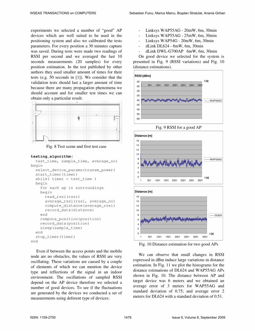
experiments we selected a number of “good” AP
devices which are well suited to be used in the
positioning system and also we calibrated the tests
parameters. For every position a 30 minutes capture
was saved. During tests were made two readings of
RSSI per second and we averaged the last 10
seconds measurements (20 samples) for every
position estimation. In the test published by other
authors they used smaller amount of times for their
tests (e.g. 50 seconds in [1]). We consider that the
validation tests should last a larger amount of time
because there are many propagation phenomena we
should account and for smaller test times we can
obtain only a particular result.
Fig. 8 Test scene and first test case
testing_algorithm(
test_time, sample_time, average_no)
begin
select_device_params(transm_power)
start_timer(timer)
while( timer < test_time )
begin
for each ap in surroundings
begin
read_rssi(rssi)
average_rssi(rssi, average_no)
compute_distance(average_rssi)
record_data(distance)
end
compute_position(position)
record_data(position)
sleep(sample_time)
end
stop_timer(timer)
end
Even if between the access points and the mobile
node are no obstacles, the values of RSSI are very
oscillating. These variations are caused by a couple
of elements of which we can mention the device
type and reflections of the signal in an indoor
environment. The oscillations of sampled RSSI
depend on the AP device therefore we selected a
number of good devices. To see if the fluctuations
are generated by the devices we conducted a set of
measurements using deferent type of devices:
- Linksys WAP55AG - 20mW, 6m, 30min
- Linksys WAP55AG - 25mW, 6m, 30min
- Linksys WAP54G - 20mW, 6m, 30min
- dLink DL624 - 8mW, 6m, 30min
- dLink DWL-G700AP 6mW, 6m, 30min
On good device we selected for the system is
presented in Fig. 9 (RSSI variations) and Fig. 10
(distance estimations).
RSSI [dBm]
-60
-55
-50
-45
-40
-35
-30
-25
-20
1 501 1001 1501 2001 2501 3001 3501
t [s]
WAP55AG
Fig. 9 RSSI for a good AP
Distance [m]
0
2
4
6
8
10
12
14
16
1 501 1001 1501 2001 2501 3001 3501t [s]
WAP55AG
Distance [m]
0
2
4
6
8
10
12
14
16
1 501 1001 1501 2001 2501 3001 3501
t [s]
DL624
Fig. 10 Distance estimation for two good APs
We can observe that small changes in RSSI
expressed in dBm induce large variations in distance
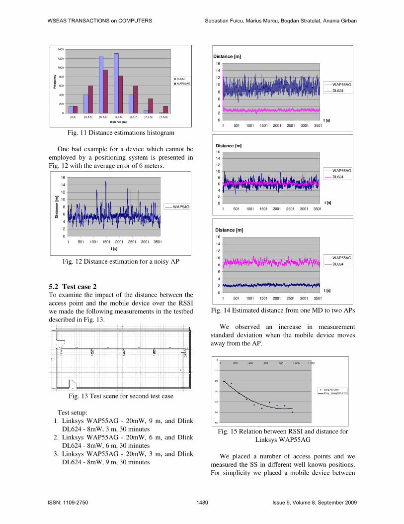
estimation. In Fig. 11 we plot the histograms for the
distance estimations of DL624 and WAP55AG APs
shown in Fig. 10. The distance between AP and
target device was 6 meters and we obtained an
average error of 3 meters for WAP55AG and
standard deviation of 0.75; and average error 2
meters for DL624 with a standard deviation of 0.51.
WSEAS TRANSACTIONS on COMPUTERS Sebastian Fuicu, Marius Marcu, Bogdan Stratulat, Anania Girban
ISSN: 1109-2750 1479 Issue 9, Volume 8, September 2009
0
200
400
600
800
1000
1200
1400
[0,5) [5,5.5) [5.5,6) [6,6.5) [6.5,7) [7,7.5) [7.5,8)
Distance [m]
Fre
qu
en
cy
DL624
WAP55AG
Fig. 11 Distance estimations histogram
One bad example for a device which cannot be
employed by a positioning system is presented in
Fig. 12 with the average error of 6 meters.
0
2
4
6
8
10
12
14
16
1 501 1001 1501 2001 2501 3001 3501
t [s]
Dis
tan
ce [
m]
WAP54G
Fig. 12 Distance estimation for a noisy AP
5.2 Test case 2 To examine the impact of the distance between the
access point and the mobile device over the RSSI
we made the following measurements in the testbed
described in Fig. 13.
Fig. 13 Test scene for second test case
Test setup:
1. Linksys WAP55AG - 20mW, 9 m, and Dlink
DL624 - 8mW, 3 m, 30 minutes
2. Linksys WAP55AG - 20mW, 6 m, and Dlink
DL624 - 8mW, 6 m, 30 minutes
3. Linksys WAP55AG - 20mW, 3 m, and Dlink
DL624 - 8mW, 9 m, 30 minutes
Distance [m]
0
2
4
6
8
10
12
14
16
1 501 1001 1501 2001 2501 3001 3501
t [s]
WAP55AG
DL624
Distance [m]
0
2
4
6
8
10
12
14
16
1 501 1001 1501 2001 2501 3001 3501
t [s]
WAP55AG
DL624
Distance [m]
0
2
4
6
8
10
12
14
16
1 501 1001 1501 2001 2501 3001 3501
t [s]
WAP55AG
DL624
Fig. 14 Estimated distance from one MD to two APs
We observed an increase in measurement
standard deviation when the mobile device moves
away from the AP.
-60
-50
-40
-30
-20
-10
0
0 200 400 600 800 1,000 1,200
dwlg700-210
Poly. (dwlg700-210)
Fig. 15 Relation between RSSI and distance for
Linksys WAP55AG
We placed a number of access points and we
measured the SS in different well known positions.
For simplicity we placed a mobile device between
WSEAS TRANSACTIONS on COMPUTERS Sebastian Fuicu, Marius Marcu, Bogdan Stratulat, Anania Girban
ISSN: 1109-2750 1480 Issue 9, Volume 8, September 2009
two APs, from 1 meter to 1 meter. For every
position a 30 minutes capture was saved. The
relation between the received signal strength and the
distance between emitter and receiver for some
devices are presented in Fig. 15.
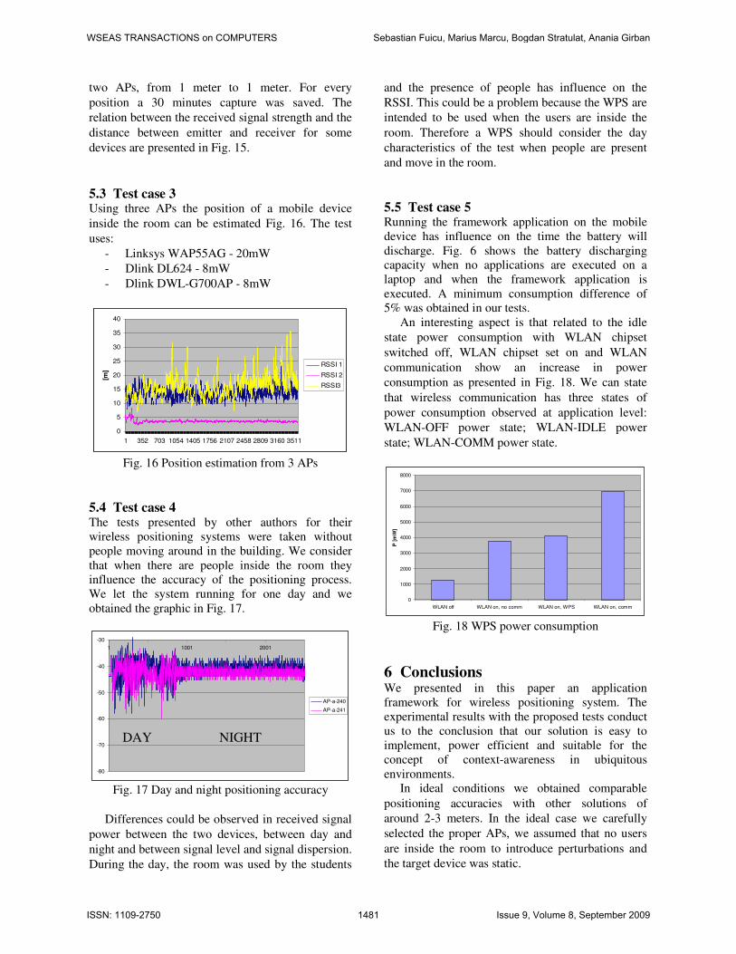
5.3 Test case 3 Using three APs the position of a mobile device
inside the room can be estimated Fig. 16. The test
uses:
- Linksys WAP55AG - 20mW
- Dlink DL624 - 8mW
- Dlink DWL-G700AP - 8mW
0
5
10
15
20
25
30
35
40
1 352 703 1054 1405 1756 2107 2458 2809 3160 3511
[m]
RSSI 1
RSSI 2
RSSI3
Fig. 16 Position estimation from 3 APs
5.4 Test case 4 The tests presented by other authors for their
wireless positioning systems were taken without
people moving around in the building. We consider
that when there are people inside the room they
influence the accuracy of the positioning process.
We let the system running for one day and we
obtained the graphic in Fig. 17.
-80
-70
-60
-50
-40
-30
1 1001 2001
AP-a-240
AP-a-241
Fig. 17 Day and night positioning accuracy
Differences could be observed in received signal
power between the two devices, between day and
night and between signal level and signal dispersion.
During the day, the room was used by the students
and the presence of people has influence on the
RSSI. This could be a problem because the WPS are
intended to be used when the users are inside the
room. Therefore a WPS should consider the day
characteristics of the test when people are present
and move in the room.
5.5 Test case 5 Running the framework application on the mobile
device has influence on the time the battery will
discharge. Fig. 6 shows the battery discharging
capacity when no applications are executed on a
laptop and when the framework application is
executed. A minimum consumption difference of
5% was obtained in our tests.
An interesting aspect is that related to the idle
state power consumption with WLAN chipset
switched off, WLAN chipset set on and WLAN
communication show an increase in power
consumption as presented in Fig. 18. We can state
that wireless communication has three states of
power consumption observed at application level:
WLAN-OFF power state; WLAN-IDLE power
state; WLAN-COMM power state.
0
1000
2000
3000
4000
5000
6000
7000
8000
WLAN off WLAN on, no comm WLAN on, WPS WLAN on, comm
P [
mW
]
Fig. 18 WPS power consumption
6 Conclusions We presented in this paper an application
framework for wireless positioning system. The
experimental results with the proposed tests conduct
us to the conclusion that our solution is easy to
implement, power efficient and suitable for the
concept of context-awareness in ubiquitous
environments.
In ideal conditions we obtained comparable
positioning accuracies with other solutions of
around 2-3 meters. In the ideal case we carefully
selected the proper APs, we assumed that no users
are inside the room to introduce perturbations and
the target device was static.
DAY NIGHT
WSEAS TRANSACTIONS on COMPUTERS Sebastian Fuicu, Marius Marcu, Bogdan Stratulat, Anania Girban
ISSN: 1109-2750 1481 Issue 9, Volume 8, September 2009
In case we consider real life usage scenarios,
there are a lot of aspects which pose serious
problems to any wireless positioning system:
- AP device changes: in case one AP in the
system is changed (position, device equipment,
device type, orientation, etc.), the positioning
system should be recalibrated.
- Environment changes: adding, removing or
changing objects positions inside the room may
influence the accuracy of the positioning
system and in some cases need recalibration.
- Mobile device changes: when target device is
changing its position, the accuracy of the
positioning decrease due to: device orientation,
device speed, etc.
- User density changes: when the test scene is
used by other people, they influence the
propagation model and further the accuracy of
the position estimation.
ACKNOWLEDGEMENT This work was supported by the grant
680/19.01.2009 from the Romanian Ministry of
Education CNCSIS.
References:
[1] U. Grosmann, C. Rohrig, S. Hakobyan, T.
Domin, and M. Dalhaus, “WLAN indoor
positioning based on Euclidian distance and
interpolation”, Proceedings of the 8th Wireless
Technologies Kongress, pp. 296-305,
Dortmund, Germany, 2006.
[2] G. Retscher, E. Moser, D. Vredeveld and D.
Heberling, “Performance and Accuracy Test of
the WLAN Indoor Positioning System ipos”,
Proc. of the 3rd
Workshop on Positioning,
navigation and Communication (WPNC’06),
pp. 7-14, 2006.
[3] Dylan McGrath, GSM handsets to integrate
GPS, EETimes, Dec. 2007.
[4] H. Lim, L. Kung, J.C. Hou, H. Luo, Zero-
Configuration, Robust Indoor Localization:
Theory and Experimentation, INFOCOM 2006.
25th IEEE International Conference on
Computer Communications. Proceedings, pp.
1-12, 2006.
[5] M. Broxton, J. Lifton, J. Paradiso, “Localizing
a Sensor Network via Collaborative Processing
of Global Stimuli”, Proceedings of the Second
European Workshop on Wireless Sensor
Networks, pp. 321-332, 2005.
[6] A.A. Ali and A.S. Omar, “Time of Arrival
Estimation for WLAN Indoor Positioning
Systems using Matrix Pencil Super Resolution
Algorithm”, Proceedings of the 2nd
Workshop
on Positioning, Navigation and
Communication, WPNC’05, pp. 11-20, 2005.
[7] C. Zhang , M.J. Kuhn, M. Brandon, A.E.
Fathy, M. Mahfouz, “High Resolution Uwb
Indoor Localization System Operating At 8 and
24 GHz Utilizing Time Difference Of Arrival
Approach”, National Radio Science Meeting,
2006.
[8] Xinrong Li, Kaveh Pahlavan, “Super-
Resolution TOA Estimation With Diversity for
Indoor Geolocation,” IEEE Transactions on
Wireless Communications vol.3 No.1., pp. 224-
234, 2004.
[9] J.C. Chen, K. Yao, R.E. Hudson, “Source
localization and beamforming”, IEEE Signal
Processing Magazine, Vol. 19, No. 2, 2002, pp.
30-39.
[10] N.B. Priyantha, A. Chakraborty, H.
Balakrishnan, “The Cricket Location-Support
System”, Proceedings of the 6th ACM
International Conference on Mobile Computing
and Networking (ACM MOBICOM), 2000,
pp.32-43.
[11] B. Li, Y. Wang, H.K. Lee, A.G. Dempster, C.
Rizos, “A new method for yielding a database
of location fingerprints in WLAN”, IEE
Proceedings Communications, Vol. 152, No. 5,
2005, pp. 580-586.
[12] B.Li, J. Salter, A.G. Dempster. C. Rizos,
“Indoor positioning techniques based on
Wireless LAN”, First IEEE Int. Conf. on
Wireless Broadband & Ultra Wideband
Communications, 2006.
[13] U. Grossmann, M. Schauch, S. Hakobyan,
“The accuracy of algorithms for WLAN indoor
positioning and the standardization of signal
reception for different mobile devices”,
International Journal of Computing, vol. 6, no.
1, pp. 103-109, 2007.
[14] S. Fuicu, M. Marcu, B. Stratulat, I. stratulat, A.
Girban, “An open, low power framework for
WLAN indoor positioning system”, 13th
WSEAS CSCC Multiconference, Int. Conf. on
Computers, 23-25 July 2009.
[15] J. Yiming, S. Biaz, S. Pandey, P. Agrawal,
“ARIADNE: A Dynamic Indoor Signal Map
Construction and Localization System”,
Proceedings of the 4th International Conference
on Mobile Systems, Applications and Services,
2006, pp. 151-164.
WSEAS TRANSACTIONS on COMPUTERS Sebastian Fuicu, Marius Marcu, Bogdan Stratulat, Anania Girban
ISSN: 1109-2750 1482 Issue 9, Volume 8, September 2009
[16] P. Bahl, V.N. Padmanabhan, „RADAR: An In-
Building RF-Based User Location and
Tracking System”, INFOCOM 2000.
Nineteenth Annual Joint Conference of the
IEEE Computer and Communications
Societies. Proceedings. IEEE, Vol.2, 2000,
pp.775-784.
[17] A. Karakos, I. Kouris, “Wireless positioning in
a university library”, WSEAS Transactions on
Circuits and Systems. Vol. 4, no. 7, pp. 455-
462. July 2005.
[18] M. Marcu, D. Tudor, S. Fuicu, S. Copil-Crisan,
F. Maticu, M. Micea, “Power Efficiency Study
of Multi-threading Applications for Multi-core
Mobile Systems”, WSEAS Transactions on
Computers, Issue 12, Volume 7, December
2008.
[19] M. Marcu, M. Vladutiu, H. Moldovan,
“Microprocessor Thermal Characterization
using Thermal Benchmark Software”, WSEAS
TRANSACTIONS on COMPUTERS, Issue 11,
Volume 5, ISSN 1109-2750, pp. 2628-2633,
November 2006.
[20] M. Marcu, S. Fuicu, A. Girban, and M. Popa,
“Experimental Test Cases for Wireless
Positioning System”, IEEE International
Conference on "Computer as a Tool",
EUROCON 2007, Warsaw, Poland, Sep. 2007,
pp. 530-537.
[21] M. Marcu, S. Fuicu, A. Girban, “Local
Wireless Positioning System”, 4th International
Symposium on Applied Computational
Intelligence and Informatics, 2007. SACI '07,
Timisoara, Romania, May. 2007, pp. 171-176.
[22] M. Marcu, S. Fuicu, A. Girban, “A
mathematical model for Wireless LAN indoor
positioning system”, The 10th International
Conference of TENSOR Society on
Differential Geometry & Its Applications and
Mathematical Foundations of Information
Sciences & Its Applications, TENSOR 2008.
[23] J.C. Chen, K. Yao, R.E. Hudson, “Source
localization and beamforming”, IEEE Signal
Processing Magazine, Vol. 19, No. 2, 2002, pp.
30-39
WSEAS TRANSACTIONS on COMPUTERS Sebastian Fuicu, Marius Marcu, Bogdan Stratulat, Anania Girban
ISSN: 1109-2750 1483 Issue 9, Volume 8, September 2009