Embed Size (px)
Citation preview
leads us to consider the influence of concrete age on theradiometric signals.
Figure 6 gives another type of result, namely, the radio-metric signals in the case in which the medium is consideredto be homogeneous. The more absorbent the medium, theweaker the signals collected.
ŽIt can be seen that an evolution of 3]12 years i.e., a.reduction of 0.5 in permittivity over the entire depth corre-
sponds to a small signal variation.We think the dispersion of measurement data is the result
of the ambient humidity that influences the first two centime-ters of the concrete. In fact, hydration or dehydrationphenomena in this layer change the relative permittivityconsiderably.
6. CONCLUSION
Microwave radiometry is a technique capable of distinguish-ing local thermal variations in concrete at thicknesses of theorder of 10 cm, as a result of duct heating.
The feasibility study presented in this article examines anumerical model of this application, first in the case ofconstant permittivity and then considering the existence of apermittivity gradient within the concrete.
A better agreement between theory and experiment isobserved when a permittivity gradient within the concrete istaken into account.
REFERENCES
1. B. Bocquet, A. Mamouni, J. C. Van de Velde, and Y. Leroy,‘‘Imagerie Thermique par Radiometrie Microonde,’’ Re¨. Phys.Appl., Vol. 23, 1988, pp. 1273]1279.
2. F. Bardati, V. J. Brown, and P. Tognolatti, ‘‘Temperature Recon-struction in Dielectric Cylinder by Multifrequency MicrowaveRadiometry,’’ J. Electron. Wa¨es Appl., Vol. 7, No. 11, 1993, pp.1549]1571.
3. S. Mizushina, Y. Hamamura, and T. Suguira, ‘‘A Three BandMicrowave Radiometer System for Non-Invasive Measurementof the Temperature,’’ IEEE MTT-S Int. Microwa e Symp. Digest,1986, pp. 759]762.
4. A. Mamouni, Y. Leroy, B. Bocquet, J. C. Van de Velde, and Ph.Gelin, ‘‘Computation of Near-Field Microwave Radiometric Sig-nals: Definition and Experimental Verification,’’ IEEE Trans.Microwa e Theory Tech., Vol. MTT-39, No. 1, 1991, pp. 124]132.
5. B. Bocquet, J. C. Van de Velde, A. Mamouni, and Y. Leroy,‘‘Non Destructive Thermometry by Means of Microwave Ra-diometry,’’ Microwa e Processing of Materials IV, MRS sympo-sium, 1994, pp. 143]154.
6. J. C. Van de Velde and Constant, French Patent 9101344, June1993.
7. R. Mensi, P. Acker, and A. Attolou, ‘‘Sechage du Beton: Analyse´ ´et Modelisation,’’ Mater. Struct., Vol. 21, 1988, pp. 3]12.´
8. F. Kreith, Transmission de la Chaleur et Thermodynamique, Mas-son et Cie, Paris, 1967.
´9. X. Derobert, ‘‘Methodes d’Auscultation Electromagnetique du´ ´Beton Arme et Precontraint par Radiometrie et Imagerie Active´ ´ ´ ´Microonde,’’ Ph.D. thesis, University of Sc. and Techn. of Lille,1995.
10. J. R. Wait, Electromagnetic Wa¨es in Stratified Media, Macmillan,New York, 1962, Chaps. 3 and 4.
Q 1997 John Wiley & Sons, Inc.CCC 0895-2477r97
EFFECTS OF A FIN EDGE CLOSE TOA POINT CAUSTIC OF A GREGORIANANTENNAF. Capolino1, P. Bussotti1, L. Borselli2, M. Albani2, and S. Maci11Department of Electrical EngineeringUniversity of FlorenceVia S. Marta 3Florence, Italy2College of EngineeringUniversity of SienaVia Roma 5653100, Siena, Italy
Recei ed 11 July 1996
ABSTRACT: The problem of edge diffraction close to a point caustic isanalyzed in a typical dual-reflector Gregorian antenna in offset configu-ration. The diffraction phenomenon is produced by a perfectly conduct-ing fin located between the feeder and the main reflector. This fin issometimes used to reduce the coupling between the primary feed and themain reflector. For the sake of simplicity, the two-dimensional case isstudied here, but the present technique can also be applied to practicalthree-dimensional configurations. Q 1997 John Wiley & Sons, Inc.Microwave Opt Technol Lett 14, 20]23, 1997.
Key words: edge diffraction; reflector antennas; antenna feeds
1. INTRODUCTION
High-gain reflector antennas for space applications some-times require pressing performances of cross-polarization lev-els. Gregorian antennas in offset configuration are largelyused in these applications, because they permit one to com-pensate for the deformation of the current lines on the main
w xreflector, thus yielding excellent polarization purity 1 . Nev-ertheless, this performance can be deteriorated by undesiredcoupling mechanisms such as the direct illumination of themain reflector from the side lobes of the primary field. Viceversa, it may be desirable to minimize the coupling of thenear field produced by the main reflector currents with the
Žprimary feeding structure. Indeed, because the feeder i.e., a.horn antenna has a metallic structure essentially concen-
trated close to the subreflector focus, its scattering can pro-duce a refocalization of rays through the dual reflector sys-tem; thus, cross-polarization level may increase.
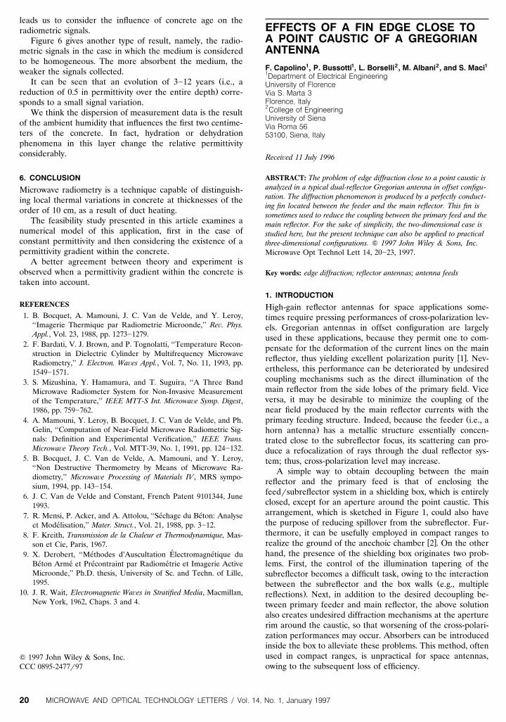
A simple way to obtain decoupling between the mainreflector and the primary feed is that of enclosing thefeedrsubreflector system in a shielding box, which is entirelyclosed, except for an aperture around the point caustic. Thisarrangement, which is sketched in Figure 1, could also havethe purpose of reducing spillover from the subreflector. Fur-thermore, it can be usefully employed in compact ranges to
w xrealize the ground of the anechoic chamber 2 . On the otherhand, the presence of the shielding box originates two prob-lems. First, the control of the illumination tapering of thesubreflector becomes a difficult task, owing to the interaction
Žbetween the subreflector and the box walls e.g., multiple.reflections . Next, in addition to the desired decoupling be-
tween primary feeder and main reflector, the above solutionalso creates undesired diffraction mechanisms at the aperturerim around the caustic, so that worsening of the cross-polari-zation performances may occur. Absorbers can be introducedinside the box to alleviate these problems. This method, oftenused in compact ranges, is unpractical for space antennas,owing to the subsequent loss of efficiency.
MICROWAVE AND OPTICAL TECHNOLOGY LETTERS / Vol. 14, No. 1, January 199720
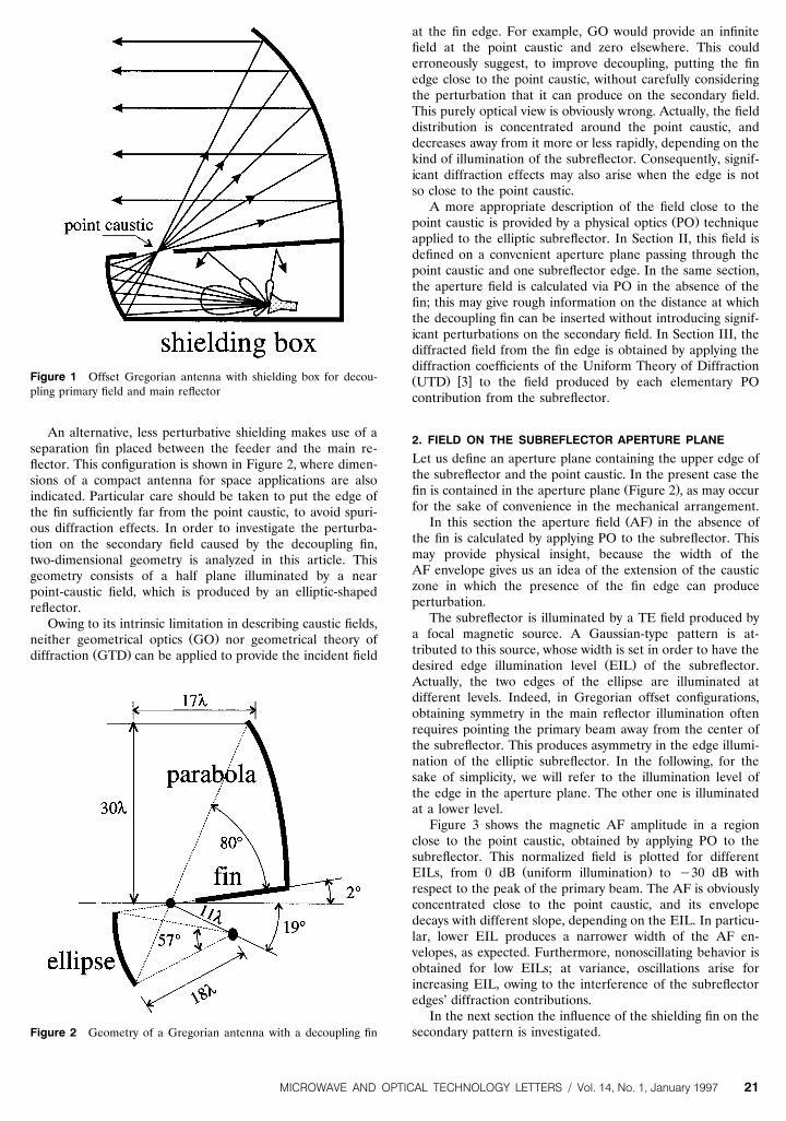
Figure 1 Offset Gregorian antenna with shielding box for decou-pling primary field and main reflector
An alternative, less perturbative shielding makes use of aseparation fin placed between the feeder and the main re-flector. This configuration is shown in Figure 2, where dimen-sions of a compact antenna for space applications are alsoindicated. Particular care should be taken to put the edge ofthe fin sufficiently far from the point caustic, to avoid spuri-ous diffraction effects. In order to investigate the perturba-tion on the secondary field caused by the decoupling fin,two-dimensional geometry is analyzed in this article. Thisgeometry consists of a half plane illuminated by a nearpoint-caustic field, which is produced by an elliptic-shapedreflector.
Owing to its intrinsic limitation in describing caustic fields,Ž .neither geometrical optics GO nor geometrical theory of
Ž .diffraction GTD can be applied to provide the incident field
Figure 2 Geometry of a Gregorian antenna with a decoupling fin
at the fin edge. For example, GO would provide an infinitefield at the point caustic and zero elsewhere. This coulderroneously suggest, to improve decoupling, putting the finedge close to the point caustic, without carefully consideringthe perturbation that it can produce on the secondary field.This purely optical view is obviously wrong. Actually, the fielddistribution is concentrated around the point caustic, anddecreases away from it more or less rapidly, depending on thekind of illumination of the subreflector. Consequently, signif-icant diffraction effects may also arise when the edge is notso close to the point caustic.
A more appropriate description of the field close to theŽ .point caustic is provided by a physical optics PO technique
applied to the elliptic subreflector. In Section II, this field isdefined on a convenient aperture plane passing through thepoint caustic and one subreflector edge. In the same section,the aperture field is calculated via PO in the absence of thefin; this may give rough information on the distance at whichthe decoupling fin can be inserted without introducing signif-icant perturbations on the secondary field. In Section III, thediffracted field from the fin edge is obtained by applying thediffraction coefficients of the Uniform Theory of DiffractionŽ . w xUTD 3 to the field produced by each elementary POcontribution from the subreflector.
2. FIELD ON THE SUBREFLECTOR APERTURE PLANE
Let us define an aperture plane containing the upper edge ofthe subreflector and the point caustic. In the present case the
Ž .fin is contained in the aperture plane Figure 2 , as may occurfor the sake of convenience in the mechanical arrangement.
Ž .In this section the aperture field AF in the absence ofthe fin is calculated by applying PO to the subreflector. Thismay provide physical insight, because the width of theAF envelope gives us an idea of the extension of the causticzone in which the presence of the fin edge can produceperturbation.
The subreflector is illuminated by a TE field produced bya focal magnetic source. A Gaussian-type pattern is at-tributed to this source, whose width is set in order to have the
Ž .desired edge illumination level EIL of the subreflector.Actually, the two edges of the ellipse are illuminated atdifferent levels. Indeed, in Gregorian offset configurations,obtaining symmetry in the main reflector illumination oftenrequires pointing the primary beam away from the center ofthe subreflector. This produces asymmetry in the edge illumi-nation of the elliptic subreflector. In the following, for thesake of simplicity, we will refer to the illumination level ofthe edge in the aperture plane. The other one is illuminatedat a lower level.
Figure 3 shows the magnetic AF amplitude in a regionclose to the point caustic, obtained by applying PO to thesubreflector. This normalized field is plotted for different
Ž .EILs, from 0 dB uniform illumination to y30 dB withrespect to the peak of the primary beam. The AF is obviouslyconcentrated close to the point caustic, and its envelopedecays with different slope, depending on the EIL. In particu-lar, lower EIL produces a narrower width of the AF en-velopes, as expected. Furthermore, nonoscillating behavior isobtained for low EILs; at variance, oscillations arise forincreasing EIL, owing to the interference of the subreflectoredges’ diffraction contributions.
In the next section the influence of the shielding fin on thesecondary pattern is investigated.
MICROWAVE AND OPTICAL TECHNOLOGY LETTERS / Vol. 14, No. 1, January 1997 21
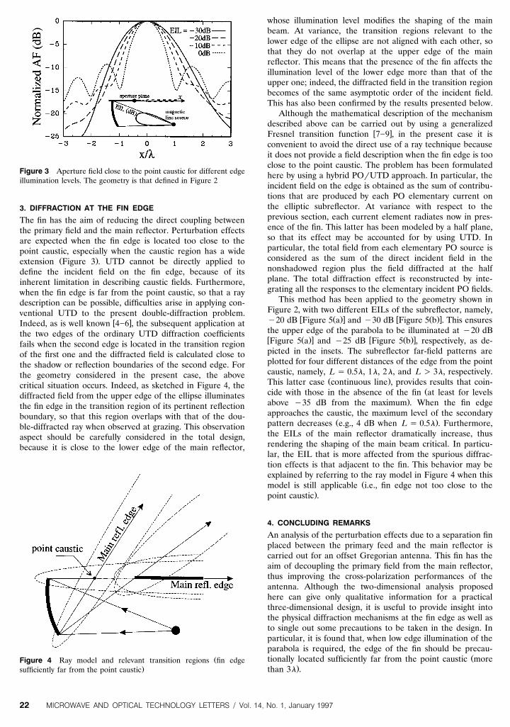
Figure 3 Aperture field close to the point caustic for different edgeillumination levels. The geometry is that defined in Figure 2
3. DIFFRACTION AT THE FIN EDGE
The fin has the aim of reducing the direct coupling betweenthe primary field and the main reflector. Perturbation effectsare expected when the fin edge is located too close to thepoint caustic, especially when the caustic region has a wide
Ž .extension Figure 3 . UTD cannot be directly applied todefine the incident field on the fin edge, because of itsinherent limitation in describing caustic fields. Furthermore,when the fin edge is far from the point caustic, so that a raydescription can be possible, difficulties arise in applying con-ventional UTD to the present double-diffraction problem.
w xIndeed, as is well known 4]6 , the subsequent application atthe two edges of the ordinary UTD diffraction coefficientsfails when the second edge is located in the transition regionof the first one and the diffracted field is calculated close tothe shadow or reflection boundaries of the second edge. Forthe geometry considered in the present case, the abovecritical situation occurs. Indeed, as sketched in Figure 4, thediffracted field from the upper edge of the ellipse illuminatesthe fin edge in the transition region of its pertinent reflectionboundary, so that this region overlaps with that of the dou-ble-diffracted ray when observed at grazing. This observationaspect should be carefully considered in the total design,because it is close to the lower edge of the main reflector,
ŽFigure 4 Ray model and relevant transition regions fin edge.sufficiently far from the point caustic
whose illumination level modifies the shaping of the mainbeam. At variance, the transition regions relevant to thelower edge of the ellipse are not aligned with each other, sothat they do not overlap at the upper edge of the mainreflector. This means that the presence of the fin affects theillumination level of the lower edge more than that of theupper one; indeed, the diffracted field in the transition regionbecomes of the same asymptotic order of the incident field.This has also been confirmed by the results presented below.
Although the mathematical description of the mechanismdescribed above can be carried out by using a generalized
w xFresnel transition function 7]9 , in the present case it isconvenient to avoid the direct use of a ray technique becauseit does not provide a field description when the fin edge is tooclose to the point caustic. The problem has been formulatedhere by using a hybrid POrUTD approach. In particular, theincident field on the edge is obtained as the sum of contribu-tions that are produced by each PO elementary current onthe elliptic subreflector. At variance with respect to theprevious section, each current element radiates now in pres-ence of the fin. This latter has been modeled by a half plane,so that its effect may be accounted for by using UTD. Inparticular, the total field from each elementary PO source isconsidered as the sum of the direct incident field in thenonshadowed region plus the field diffracted at the halfplane. The total diffraction effect is reconstructed by inte-grating all the responses to the elementary incident PO fields.
This method has been applied to the geometry shown inFigure 2, with two different EILs of the subreflector, namely,
w Ž .x w Ž .xy20 dB Figure 5 a and y30 dB Figure 5 b . This ensuresthe upper edge of the parabola to be illuminated at y20 dBw Ž .x w Ž .xFigure 5 a and y25 dB Figure 5 b , respectively, as de-picted in the insets. The subreflector far-field patterns areplotted for four different distances of the edge from the pointcaustic, namely, L s 0.5l, 1l, 2l, and L ) 3l, respectively.
Ž .This latter case continuous line , provides results that coin-Žcide with those in the absence of the fin at least for levels
.above y35 dB from the maximum . When the fin edgeapproaches the caustic, the maximum level of the secondary
Ž .pattern decreases e.g., 4 dB when L s 0.5l . Furthermore,the EILs of the main reflector dramatically increase, thusrendering the shaping of the main beam critical. In particu-lar, the EIL that is more affected from the spurious diffrac-tion effects is that adjacent to the fin. This behavior may beexplained by referring to the ray model in Figure 4 when this
Žmodel is still applicable i.e., fin edge not too close to the.point caustic .
4. CONCLUDING REMARKS
An analysis of the perturbation effects due to a separation finplaced between the primary feed and the main reflector iscarried out for an offset Gregorian antenna. This fin has theaim of decoupling the primary field from the main reflector,thus improving the cross-polarization performances of theantenna. Although the two-dimensional analysis proposedhere can give only qualitative information for a practicalthree-dimensional design, it is useful to provide insight intothe physical diffraction mechanisms at the fin edge as well asto single out some precautions to be taken in the design. Inparticular, it is found that, when low edge illumination of theparabola is required, the edge of the fin should be precau-
Žtionally located sufficiently far from the point caustic more.than 3l .
MICROWAVE AND OPTICAL TECHNOLOGY LETTERS / Vol. 14, No. 1, January 199722
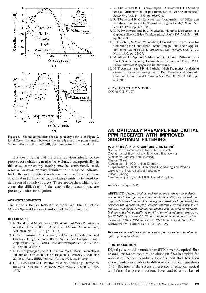
Figure 5 Secondary patterns for the geometry defined in Figure 2,for different distances between the fin edge and the point caustic.Ž . Ž .a Subreflector EIL s y20 dB, b subreflector EIL s y30 dB
It is worth noting that the same radiation integral of thepresent formulation can also be evaluated asymptotically. Inthis case, complex ray tracing may be conveniently used,when a Gaussian primary illumination is assumed. Alterna-tively, the multiple-Gaussian-beam decomposition technique
w xdescribed in 10 may be used, which permits us to avoid thedefinition of complex sources. These approaches, which over-come the difficulties of the caustic-field description, arepresently under investigation.
ACKNOWLEDGMENTS
The authors thanks Roberto Mizzoni and Eliana Pelaca’Ž .Alenia Spazio for useful and stimulating discussions.
REFERENCES
1. H. Tanaka and M. Mizusawa, ‘‘Elimination of Cross-Polarizationin Offset Dual Reflector Antennas,’’ Electron. Commun. Jpn.,Vol. 58-B, No. 12, 1975, pp. 71]78.
2. C. W. I. Pistorius, G. C. Clerici, and W. D. Burnside, ‘‘A DualChamber Gregorian Subreflector System for Compact RangeApplications,’’ IEEE Trans. Antennas Propagat., Vol. AP-37, No.3, 1989, pp. 305]313.
3. R. G. Kouyoumjian and P. H. Pathak, ‘‘A Uniform GeometricalTheory of Diffraction for an Edge in a Perfectly ConductingSurface,’’ Proc. IEEE, Vol. 62, No. 11, 1974, pp. 1448]1461.
4. G. L. James and G. D. Poulton, ‘‘Double Knife-Edge Diffractionfor Curved Screens,’’ Microwa es Opt. Acoust., Vol. 3, pp. 221]223,1979.
5. R. Tiberio, and R. G. Kouyoumjian, ‘‘A Uniform GTD Solutionfor the Diffraction by Strips Illuminated at Grazing Incidence,’’Radio Sci., Vol. 14, 1979, pp. 933]941.
6. R. Tiberio and R. G. Kouyoumjian, ‘‘An Analysis of Diffractionat Edges Illuminated by Transition Region Fields,’’ Radio Sci.,Vol. 17, 1982, pp. 323]336.
7. L. P. Ivrissimtzis and R. J. Marhefka, ‘‘Double Diffraction at aCoplanar Skewed Edge Configuration,’’ Radio Sci., Vol. 26, 1991,pp. 821]830.
8. F. Capolino, S. Maci, ‘‘Simplified, Closed-Form Expressions forComputing the Generalized Fresnel Integral and Their Applica-tion to Vertex Diffraction,’’ Microwa e Opt. Technol. Lett., Vol. 9,No. 1, 1995, pp. 32]37.
9. M. Albani, F. Capolino, S. Maci, and R. Tiberio, ‘‘Diffraction at aThick Screen Including Corrugations on the Top Face,’’ IEEETrans. Antennas Propagat., to be published.
10. H. T. Anastassiu and P. H. Pathak, ‘‘High-Frequency Analysis ofGaussian Beam Scattering by a Two Dimensional ParabolicContour of Finite Width,’’ Radio Sci., Vol. 30, No. 3, 1995, pp.403]503.
Q 1997 John Wiley & Sons, Inc.CCC 0895-2477r97
AN OPTICALLY PREAMPLIFIED DIGITALPPM RECEIVER WITH IMPROVEDSUBOPTIMUM FILTERINGA. J. Phillips1, R. A. Cryan2, and J. M. Senior11Centre for Communication Networks ResearchDepartment of Electrical and Electronic EngineeringManchester Metropolitan UniversityChester StreetManchester M1 5GD, United Kingdom2Department of Electrical, Electronic Engineering and PhysicsUniversity of Northumbria at NewcastleEllison BuildingNewcastle upon Tyne NE1 8ST, United Kingdom
Recei ed 1 August 1996
ABSTRACT: Original analysis and results are gi en for an optically( )preamplified digital pulse-position-modulation PPM recei er with an
impro¨ed electrical-domain filtering regime consisting of a matched filtercascaded with a pulse-shaping network. Impressi e sensiti ity results arereported, with the 21.54 photonsrbit predicted at 622 Mbitrs, surpassingboth an equi alent optically preamplified on-off keyed nonreturn-to-zero( ) ( )OOK NRZ system by 8.1 dB and the fundamental limit of such apreamplified OOK NRZ recei er. Q 1997 John Wiley & Sons, Inc.Microwave Opt Technol Lett 14, 23]28, 1997.
Key words: optical-fiber communications; pulse-position modulation-optical preamplification
1. INTRODUCTION
Ž .Digital pulse-position modulation PPM over the optical-fiberchannel exchanges some of the abundant fiber bandwidth forimpressive receiver sensitivity benefits, and thus has beenstudied widely in relation to different receiver configurationsw x1]5 . Because of the recent emergence of practical opticalamplifiers, the present authors have studied a number of
MICROWAVE AND OPTICAL TECHNOLOGY LETTERS / Vol. 14, No. 1, January 1997 23