Embed Size (px)
Citation preview

Effects of Alloying Elements on High-Temperature Oxidationand Sticking Occurring During Hot Rolling of Modified FerriticSTS430J1L Stainless Steels
DAE JIN HA, JONG SEOG LEE, NACK J. KIM, and SUNGHAK LEE
In the present study, mechanisms of sticking that occurs during hot rolling of modifiedSTS430J1L ferritic stainless steels were investigated by using a pilot-plant-scale rolling machine,and the effects of alloying elements on sticking were analyzed by the high-temperature oxidationbehavior. The hot-rolling test results indicated that the Cr oxide layer formed in a heatingfurnace was broken off and infiltrated the steel, thereby forming Cr oxides on the rolled steelsurface. Because the surface region without oxides underwent a reduction in hardness ratherthan the surface region with oxides, the thickness of the surface oxide layer favorably affectedthe resistance to sticking. The addition of Zr, Cu, and Ni to the ferritic stainless steels worked infavor of the decreased sticking, but the Si addition negatively affected the resistance to sticking.In the Si-rich steel, Si oxides were continuously formed along the interfacial area between the Croxide layer and the base steel, and interrupted the formation and growth of the Cr oxide layer.Because the Si addition played a role in increasing sticking, the reduction in Si content wasdesirable for preventing sticking.
DOI: 10.1007/s11661-011-0829-2� The Minerals, Metals & Materials Society and ASM International 2011
I. INTRODUCTION
STICKING occurring during hot rolling of steelsrepresents surface defects formed when fragments of therolled steel are stuck to the work roll, and deterioratessurface properties of both the rolled steel and the roll.[1]
It often makes serious problems such as reduction inhot-rolling productivity, roll life, and surface quality ofthe rolled steel.[2–9] However, it is difficult to solvesticking problem because sticking varies with severalrolling conditions of temperature, load, speed, andlubrication and with variety of rolled steels and rolls.
Ferritic stainless steels are ferromagnetic, and haveexcellent cold-deformability and resistance to stresscorrosion cracking, although their corrosion resistanceis worse than that of austenitic stainless steels. They canalso be hardened by heat treatments, and the phasetransformation does not occur during hot rollingbecause of their stable microstructures at room and
high temperatures. Although austenitic stainless steelscontain 8 to ~10 wt pct of Ni, ferritic stainless steelscontain a small amount of Ni (less than 1 wt pct). Ni isexpensive (about ten times more expensive than anyother alloying elements of stainless steels) because theextraction of Ni from Ni ores containing Cu requiresmany complicated processing steps. Recently, efforts toreplace expensive austenitic stainless steels with reason-ably priced ferritic stainless steels whose corrosionresistance is improved by adding alloying elements havebeen actively attempted.Sticking occurs more seriously in ferritic stainless
steels than in austenitic stainless steels.[6,7] Ferriticstainless steels have excellent hardness and strength atroom temperature, but their high-temperature hardnessdrastically decreases at about 1173 K to ~1373 K(900 �C to 1100 �C) where the actual hot rolling starts,which can result in sticking during hot rolling. Becausehigh-temperature oxidation hardens the surface of therolled steel as oxide layers or oxide particles are formedon the surface, it can favorably affect sticking.[10,11] Thisfinding indicates that sticking is determined by themutual interaction of the roll and rolled steel, and thatthe high-temperature oxidation behavior during hotrolling plays an important role. The sticking amount isalso varied with the kind of ferritic stainless steelsbecause their alloying elements affect the high-temper-ature hardness and oxidation.[12–14] Furthermore, theaddition or modification of alloying elements is requiredto replace austenitic stainless steels, which can cause theserious sticking and consequent reduction in productiv-ity of ferritic stainless steels. Therefore, the effects ofalloying elements on sticking are essentially needed toprevent or minimize sticking and the development of
DAE JIN HA, Post Doctoral Research Associate, is with the Centerfor Advanced Aerospace Materials, Pohang University of Science andTechnology, Pohang 790-784, Korea. JONG SEOG LEE, PrincipalResearcher, is with the Research Planning Group, Technical ResearchLab., POSCO, Pohang 790-785, Korea. NACK J. KIM, Professor, iswith the Graduate Institute of Ferrous Technology, Pohang Universityof Science and Technology, and also with the Center for AdvancedAerospace Materials, Pohang University of Science and Technology.SUNGHAK LEE, Professor, is with the Center for AdvancedAeroSpace Materials, Pohang University of Science and Technology,and also with the Department of Materials Science and EngineeringPohang University of Science and Technology. Contact e-mail:[email protected]
Manuscript submitted February 9, 2011.Article published online July 20, 2011
74—VOLUME 43A, JANUARY 2012 METALLURGICAL AND MATERIALS TRANSACTIONS A
advanced ferritic stainless steels with improved corro-sion resistance, but only limited information is available.
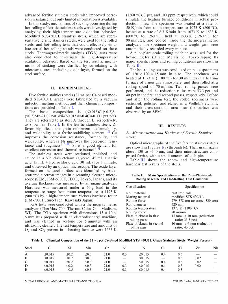
In this study, mechanisms of sticking occurring duringhot rolling of ferritic stainless steels were investigated byanalyzing their high-temperature oxidation behavior.Modified STS430J1L stainless steels, which are repre-sentative ferritic stainless steels, were used for the rolledsteels, and hot-rolling tests that could effectively simu-late actual hot-rolling stands were conducted on thesesteels. Thermogravimetric analysis (TGA) tests werealso conducted to investigate the high-temperatureoxidation behavior. Based on the test results, mecha-nisms of sticking were clarified by correlating withmicrostructures, including oxide layer, formed on thesteel surface.
II. EXPERIMENTAL
Five ferritic stainless steels (21 wt pct Cr-based mod-ified STS430J1L grade) were fabricated by a vacuuminduction melting method, and their chemical composi-tions are provided in Table I.
The basic composition is (£0.015)C-(£0.2)Si-(£0.3)Mn-21.0Cr-0.3Ni-(£0.015)N-0.4Cu-0.3Ti (wt pct).They are referred to as steel A through E, respectively,as shown in Table I. In the ferritic stainless steels, Zrfavorably affects the grain refinement, deformability,and weldability as a ferrite-stabilizing element.[15] Cuimproves the corrosion resistance, formability, andweldability, whereas Ni improves the corrosion resis-tance and toughness.[16–18] Si is a good element forexcellent corrosion and thermal resistance.[19]
The stainless steels were sectioned, polished, andetched in a Viellela’s etchant (glycerol 45 mL+nitricacid 15 mL+hydrochloric acid 30 mL) for 1 minute,and observed by an optical microscope. The oxide layerformed on the steel surface was identified by back-scattered electron images in a scanning electron micro-scope (SEM, JSM-6330F, JEOL, Tokyo, Japan), and itsaverage thickness was measured by an image analyzer.Hardness was measured under a 50-g load in thetemperature range from room temperature to 1173 K(900 �C) by a high-temperature Vickers hardness tester(FM-700, Future-Tech, Kawasaki Japan).
TGA tests were conducted with a thermogravimetricanalyzer (TherMax 700, Thermo Cahn Co., Madison,WI). The TGA specimen with dimensions 15 9 10 95 mm was prepared with an electrodischarge machine,and was cleaned in acetone for 5 minutes with anultrasonic cleaner. The test temperature and amounts ofO2 and SO2 present in a heating furnace were 1533 K
(1260 �C), 3 pct, and 100 ppm, respectively, which couldsimulate the heating furnace conditions in actual pro-duction lines. The specimen was heated at a rate of50 K/min from room temperature to 1073 K (800 �C),heated at a rate of 8.3 K/min from 1073 K to 1533 K(800 �C to 1260 �C), held at 1533 K (1260 �C) for90 minutes, and cooled inside the thermogravimetricanalyzer. The specimen weight and weight gain wereautomatically recorded every minute.A pilot-plant-scale rolling machine was used for the
hot-rolling test (Hitachi Metals Co., Tokyo Japan). Itsmajor specifications and rolling conditions are shown inTable II.The hot-rolling test was conducted on plate specimens
of 120 9 120 9 15 mm in size. The specimen washeated at 1373 K (1100 �C) for 30 minutes in a heatingfurnace of argon gas atmosphere, and then rolled at arolling speed of 70 m/min. Two rolling passes wereperformed, and the reduction ratios were 33.3 pct and40 pct in the first and second passes, respectively. Beforeand after the rolling test, the rolled specimens weresectioned, polished, and etched in a Viellela’s etchant,and their cross-sectional area near the surface wasobserved by an SEM.
III. RESULTS
A. Microstructure and Hardness of Ferritic StainlessSteels
Optical micrographs of the five ferritic stainless steelsare shown in Figures 1(a) through (e). Their grain size isabout 130 to ~140 lm, and their microstructure com-prised ferrite, with a small amount of etch pits.Table III shows the room- and high-temperature
hardness test results of the steels.
Table II. Main Specifications of the Pilot-Plant-ScaleRolling Machine and Hot-Rolling Test Conditions
Classification Specification
Roll material cast iron rollMating material modified STS 430J1LRolling force 279~378 ton (average: 330 ton)Roll diameter 720 mmRolling temperature 1373 K (1100 �C)Rolling speed 70 m/minPlate thickness in firstrolling pass
15 mm fi 10 mm (reductionratio; 33.3 pct)
Plate thickness in secondrolling pass
10 mm fi 6 mm (reductionratio; 40 pct)
Table I. Chemical Composition of the 21 wt pct Cr-Based Modified STS 430J1L Grade Stainless Steels (Weight Percent)
Steel C Si Mn Cr Ni N Cu Ti Zr Nb
A £0.015 £0.2 £0.3 21.0 0.3 £0.015 0.4 0.3 — —B £0.015 £0.2 £0.3 21.0 — £0.015 — 0.3 0.02 —C £0.015 £0.2 £0.3 21.0 — £0.015 0.4 0.3 0.02 —D £0.015 £0.2 £0.3 21.0 0.3 £0.015 0.4 0.3 0.02 —E £0.015 0.5 £0.3 21.0 0.3 £0.015 0.4 0.3 — —
METALLURGICAL AND MATERIALS TRANSACTIONS A VOLUME 43A, JANUARY 2012—75

The room-temperature hardness ranges from 150VHN to 165 VHN, and the A, D, and E steels areharder than the B and C steels. The hardness continu-ously decreases with increasing test temperature. Thehardness of the A, D, and E steels drops seriously withincreasing test temperature, and becomes lower thanthat of the B and C steels, although the hardnessdifference between the steels tends to decrease as the testtemperature increases. At 1173 K (900 �C), the hardnessis highest in the B steel, and decreases in the order of the
C, D, E, and A steels. Because the overall high-temperature hardness trend is similar in all the steels,it is expected that the variation in high-temperaturehardness would hardly affect sticking.[12,20]
B. High-Temperature Oxidation Behavior
The formation behavior of high-temperature oxidesformed during hot rolling was investigated by TGA, andthe results are shown in Figure 2. The weight gain
Fig. 1—Optical micrographs of the modified STS430J1L ferritic stainless steels: (a) A, (b) B, (c) C, (d) D, and (e) E steels. Etched by a Viellela’setchant for the stainless steels.
76—VOLUME 43A, JANUARY 2012 METALLURGICAL AND MATERIALS TRANSACTIONS A
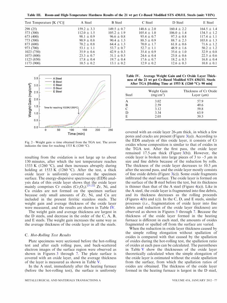
resulting from the oxidation is not large up to about130 minutes, after which the test temperature reaches1533 K (1260 �C), and then increases abruptly duringholding at 1533 K (1260 �C). After the test, a thickoxide layer is uniformly covered on the specimensurface. The energy-dispersive spectroscopy (EDS) anal-ysis data of this oxide layer shows that the oxide layermainly comprises Cr oxides (Cr2O3).
[21,22] Zr, Ni, andCu oxides are not formed on the specimen surfacebecause only small amounts of Zr, Ni, and Cu areincluded in the present ferritic stainless steels. Theweight gain and average thickness of the oxide layerwere measured, and the results are shown in Table IV.
The weight gain and average thickness are largest inthe D steels, and decrease in the order of the C, A, B,and E steels. The weight gain increases the same way asthe average thickness of the oxide layer in all the steels.
C. Hot-Rolling Test Results
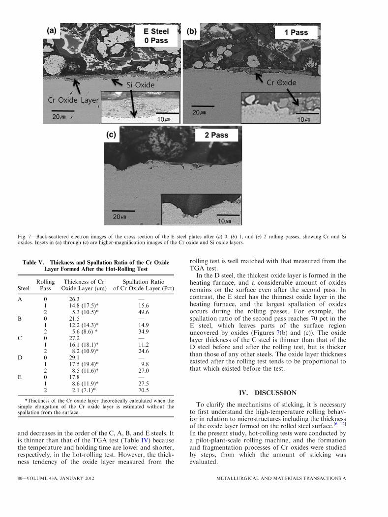
Plate specimens were sectioned before the hot-rollingtest and after each rolling pass, and back-scatteredelectron images of the surface region were observed asshown in Figures 3 through 7. The plate surface iscovered with an oxide layer, and the average thicknessof the layer is measured as shown in Table V.
In the A steel, immediately after the heating furnace(before the hot-rolling test), the surface is uniformly
covered with an oxide layer 26-lm thick, in which a fewpores and cracks are present (Figure 3(a)). According tothe EDS analysis of this oxide layer, it consists of Croxides whose composition is similar to that of oxides inthe TGA test. After the first pass, the oxide layerremained 17.5-lm thick (Figure 3(b)). However, theoxide layer is broken into large pieces of 3 to ~5 lm insize and fine debris because of the reduction by rolls.The thickness of the oxide layer decreases to 10.5 lmafter the second pass, and the oxide layer mostly consistsof fine oxide debris (Figure 3(c)). Some oxide fragmentsinfiltrated the steel surface. The oxide layer is formed onthe surface of the B steel before the test, but its thicknessis thinner than that of the A steel (Figure 4(a)). Like inthe A steel, the oxide layer is fragmented into fine debris,and its thickness decreases as the rolling proceeds(Figures 4(b) and (c)). In the C, D, and E steels, similarprocesses (i.e., fragmentation of oxide layer into finedebris and reduction of the oxide layer thickness) areobserved as shown in Figures 5 through 7. Because thethickness of the oxide layer formed in the heatingfurnace is different in each steel, the amounts of oxidesfragmented or spalled off from the surface are varied.When the reduction in oxide layer thickness caused by
the simple rolling elongation without spallation ofoxides is compared with that caused by the spallationof oxides during the hot-rolling test, the spallation ratioof oxides at each pass can be calculated. The parenthesesin Table V show the thicknesses of the oxide layertheoretically calculated when the simple elongation ofthe oxide layer is estimated without the oxide spallationfrom the surface, from which the spallation ratios ofoxides are obtained. The thickness of the oxide layerformed in the heating furnace is largest in the D steel,
Table III. Room-and High-Temperature Hardness Results of the 21 wt pct Cr-Based Modified STS 430J1L Steels (unit: VHN)
Test Temperature [K (�C)] A Steel B Steel C Steel D Steel E Steel
298 (25) 159.2 ± 3.3 149.5 ± 0.7 148.6 ± 2.0 160.4 ± 2.2 164.5 ± 1.4573 (300) 112.0 ± 1.5 105.2 ± 1.9 105.4 ± 1.0 106.0 ± 1.4 134.5 ± 1.2673 (400) 98.1 ± 0.9 96.6 ± 0.8 95.4 ± 0.7 97.3 ± 0.8 117.4 ± 1.1773 (500) 90.9 ± 0.8 90.4 ± 1.3 88.5 ± 0.9 88.7 ± 2.3 103.8 ± 1.3873 (600) 70.2 ± 0.8 64.4 ± 1.3 70.0 ± 1.7 61.8 ± 0.6 71.6 ± 1.2973 (700) 53.1 ± 1.1 53.7 ± 0.7 52.7 ± 1.1 48.9 ± 1.6 50.2 ± 1.21023 (750) 35.9 ± 0.6 42.9 ± 0.3 35.4 ± 0.9 35.6 ± 1.0 32.9 ± 0.81073 (800) 23.3 ± 0.7 31.1 ± 0.5 24.6 ± 0.4 25.8 ± 0.6 22.5 ± 0.61123 (850) 17.8 ± 0.4 19.7 ± 0.4 17.6 ± 0.7 18.2 ± 0.3 16.8 ± 0.41173 (900) 10.5 ± 0.2 13.1 ± 0.2 12.9 ± 0.2 12.6 ± 0.3 10.8 ± 0.1
Fig. 2—Weight gain vs time obtained from the TGA test. The arrowindicates the time for reaching 1533 K (1260 �C).
Table IV. Average Weight Gain and Cr Oxide Layer Thick-ness of the 21 wt pct Cr-Based Modified STS 430J1L Steels
After TGA [Holding Time at 1553 K (1260 �C): 90 min]
SteelWeight Gain(mg/cm2)
Thickness of Cr OxideLayer (lm)
A 3.02 57.9B 2.59 49.6C 3.12 59.8D 3.34 63.9E 2.05 39.5
METALLURGICAL AND MATERIALS TRANSACTIONS A VOLUME 43A, JANUARY 2012—77

Fig. 3—Back-scattered electron images of the cross section of the A steel plates after (a) 0, (b) 1, and (c) 2 rolling passes, showing Cr oxides.Insets in (b) and (c) are higher-magnification images of the Cr oxide layer.
Fig. 4—Back-scattered electron images of the cross section of the B steel plates after (a) 0, (b) 1, and (c) 2 rolling passes, showing Cr oxides.Insets in (b) and (c) are higher-magnification images of the Cr oxide layer.
78—VOLUME 43A, JANUARY 2012 METALLURGICAL AND MATERIALS TRANSACTIONS A

Fig. 5—Back-scattered electron images of the cross section of the C steel plates after (a) 0, (b) 1, and (c) 2 rolling passes, showing Cr oxides.Insets in (b) and (c) are higher-magnification images of the Cr oxide layer.
Fig. 6—Back-scattered electron images of the cross section of the D steel plates after (a) 0, (b) 1, and (c) 2 rolling passes, showing Cr oxides.Insets in (b) and (c) are higher-magnification images of the Cr oxide layer.
METALLURGICAL AND MATERIALS TRANSACTIONS A VOLUME 43A, JANUARY 2012—79
and decreases in the order of the C, A, B, and E steels. Itis thinner than that of the TGA test (Table IV) becausethe temperature and holding time are lower and shorter,respectively, in the hot-rolling test. However, the thick-ness tendency of the oxide layer measured from the
rolling test is well matched with that measured from theTGA test.In the D steel, the thickest oxide layer is formed in the
heating furnace, and a considerable amount of oxidesremains on the surface even after the second pass. Incontrast, the E steel has the thinnest oxide layer in theheating furnace, and the largest spallation of oxidesoccurs during the rolling passes. For example, thespallation ratio of the second pass reaches 70 pct in theE steel, which leaves parts of the surface regionuncovered by oxides (Figures 7(b) and (c)). The oxidelayer thickness of the C steel is thinner than that of theD steel before and after the rolling test, but is thickerthan those of any other steels. The oxide layer thicknessexisted after the rolling test tends to be proportional tothat which existed before the test.
IV. DISCUSSION
To clarify the mechanisms of sticking, it is necessaryto first understand the high-temperature rolling behav-ior in relation to microstructures including the thicknessof the oxide layer formed on the rolled steel surface.[6–12]
In the present study, hot-rolling tests were conducted bya pilot-plant-scale rolling machine, and the formationand fragmentation processes of Cr oxides were studiedby steps, from which the amount of sticking wasevaluated.
Fig. 7—Back-scattered electron images of the cross section of the E steel plates after (a) 0, (b) 1, and (c) 2 rolling passes, showing Cr and Sioxides. Insets in (a) through (c) are higher-magnification images of the Cr oxide and Si oxide layers.
Table V. Thickness and Spallation Ratio of the Cr OxideLayer Formed After the Hot-Rolling Test
SteelRollingPass
Thickness of CrOxide Layer (lm)
Spallation Ratioof Cr Oxide Layer (Pct)
A 0 26.3 —1 14.8 (17.5)* 15.62 5.3 (10.5)* 49.6
B 0 21.5 —1 12.2 (14.3)* 14.92 5.6 (8.6) * 34.9
C 0 27.2 —1 16.1 (18.1)* 11.22 8.2 (10.9)* 24.6
D 0 29.1 —1 17.5 (19.4)* 9.82 8.5 (11.6)* 27.0
E 0 17.8 —1 8.6 (11.9)* 27.52 2.1 (7.1)* 70.5
*Thickness of the Cr oxide layer theoretically calculated when thesimple elongation of the Cr oxide layer is estimated without thespallation from the surface.
80—VOLUME 43A, JANUARY 2012 METALLURGICAL AND MATERIALS TRANSACTIONS A
According to the hot-rolling test results of Figures 3through 7 and Table V, the oxide layer formed in theheating furnace is not extinguished during hot rolling,but is broken off into pieces or fragments and thenremains on the surface with an increasing number ofrolling passes. The decarburized layer formed in thefurnace before hot rolling of conventional plain carbonsteels or high-strength low alloy steels is peeled off by adescaling treatment or mostly extinguished during roughrolling. However, most of the oxide layer formed duringheating of stainless steels remains even during hotrolling unless it is artificially peeled off by applying adescaling treatment. Parts of the remaining oxide layerare broken by rolls, but a considerable amount of oxidesare distributed on the surface region. The oxides areelongated together with the base steel as the rollingproceeds, and often leave parts of the surface regionuncovered by oxides because the amount of oxides isreduced by the elongation. The total reduction ratio inthe rolling test of Figures 3 through 7 is 60 pct, and thesurface area of the steel after the rolling test increases 2.5times that before the rolling test. Thus, parts of the thickoxide layer formed on the steel surface before the rollingtest are broken off and gone. Some oxides infiltrates thesteel, but the surface regions with hardly any oxides canexist as the surface area increases. The hardness of thesurface region without oxides is significantly lower thanthat of the surface region with oxides, and parts of thesteel surface can be removed because of the reduction byrolls.[12] Oxides in the surface region contribute to theincreased surface hardness and enhance the resistance tosticking. To prevent or minimize sticking in ferriticstainless steels, therefore, it is desirable to promote anoxide layer as thick as possible in the heating furnaceand to keep the slab temperature as high as possible,whereas the descaling treatment of the oxide layershould not be applied before the rolling.
Because sticking is significantly affected by the thick-ness of the oxide layer present on the steel surface, it canbe evaluated by the initial thickness of the oxide layerand the amount of the oxide spallation as shown inTable V. The initial thickness of the surface oxide layerformed in the furnace is thickest in the D steel, anddecreases in the order of the C, A, B, and E steels. In theD steel, the thick surface oxide layer is formed in theheating furnace, and a considerable amount of the layerremains even after the rolling test (Figures 6(a) through(c)). In the other steels, the surface oxide layer thicknessdecreases with an increasing rolling pass number, butthe final thickness of the oxide layer tends to be linearlyproportional to the initial thickness of the layer formedbefore the test. Thus, the amount of sticking can beeffectively estimated by measuring and analyzing theoxide layer formed in the heating furnace.
The thickness of the oxide layer measured after theTGA test (Table IV) is proportional to that measuredafter the hot-rolling test (Table V). This result impliesthat the TGA test is useful for explaining the formationbehavior of the surface oxide layer during hot rolling.Major oxides formed in ferritic stainless steels are Croxides, and their oxidation behavior is related to Cractivity.[23,24] Oxide-forming metal elements need to
satisfy the following equation to form oxides byinteracting with oxygen[23]:
NðOÞB >
pg�2t
NðSÞO
DOVm
DBVOX
� �½1�
where NðOÞB , N
ðSÞO , m, DO, DB, Vm, and VOX are the density
of metal, solubility of oxygen in metal, infiltrationvelocity of oxide layer into metal, diffusion coefficient ofoxygen, diffusion coefficient of metal, volume of metalper 1 mole, and volume of oxygen per 1 mole,respectively. According to Eq. [1], the concentration ofoxide-forming metal elements decreases when the oxy-gen flux is prevented or the diffusion of metal elementsincreases. The Cr activity favorably affects the value ofDB and consequently the formation of Cr oxides becausethe Cr concentration required for forming Cr oxidesdecreases.Because the Cr activity is closely related to the
amount of oxides formed at high temperatures in ferriticstainless steels,[24] it can be estimated at a given hightemperature by thermodynamic calculations. Thermo-Calc,[25] which is a commercial thermodynamic calcu-lating program, was used for the calculations, and theupgraded version of TCFE2000[26,27] was used for thethermodynamic database. The given temperature is1533 K (1260 �C), which is the heating furnace temper-ature. The Cr activity is varied with contents of alloyingelements of Zr, Ni, Cu, and Si, and the results are shownin Figures 8(a) through (d). The Cr activity increases asthe contents of Cu, Zr, Ni, and Si increase.To confirm the correlation between Cr activity and
actual high-temperature oxidation behavior, the Cractivity data are compared with the TGA test data(Table IV). The effects of alloying element Cu added tothe stainless steels can be analyzed by comparing the Band C steels. The amount of oxidation as expressed bythe weight gain increases in the C steel containing0.4 wt pct Cu. As the contents of Ni and Zr increase inthe C and D steels and in the A and D steels,respectively, the amount of oxidation increases. Thus,the amount of oxidation increases with increasingamounts of Cu, Ni, and Zr, and is matched with theCr activity data. The increment of Si in the A and Esteels reduces the amount of oxidation, which shows theopposite result of Cr activity and oxidation behavior.This result might be associated with another factor inthe peculiar oxide formation behavior of Si. Thus, theeffects of the Si addition on high-temperature oxidationand sticking should be analyzed in detail.Figures 9(a) and (b) show the EDS data of the oxide
layer formed after TGA of the A and E steels. In the Esteel, spherical Si oxides (SiO2) are continuously formedalong the interfacial area between the Cr oxide layer andthe base steel (Figure 9(b)), whereas only Cr oxides arefound above the base steel in the A steel (Figure 9(a)).The mapping data of Si and O confirm the formation ofSi oxides along the interfacial area. This result indicatesthat Si oxides formed along the interfacial area canprevent the movement of Cr ions and consequently thegrowth of the Cr oxide layer. In addition, Si can act asan oxygen attractor, decrease the reaction of Cr and
METALLURGICAL AND MATERIALS TRANSACTIONS A VOLUME 43A, JANUARY 2012—81

oxygen present in the base steel, and reduce the growthof the Cr oxide layer.
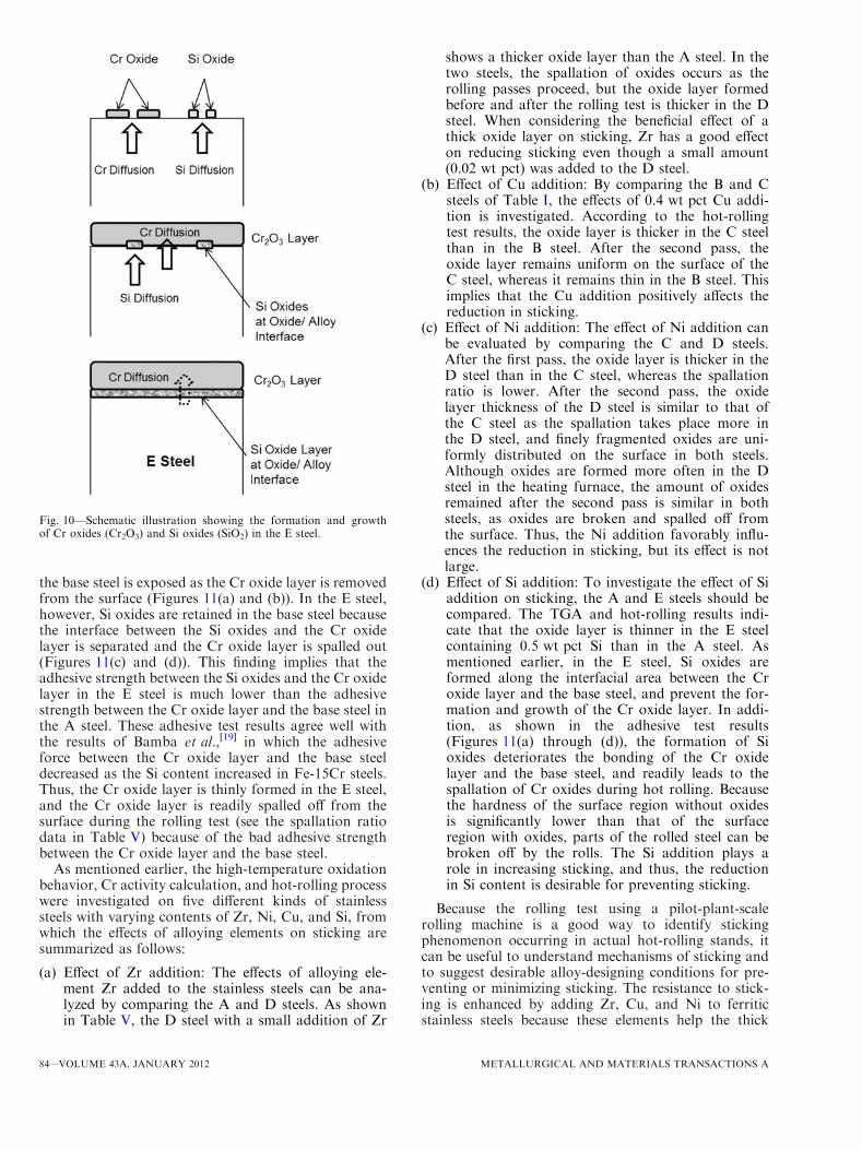
The formation processes of Si oxides along theinterfacial area and the growth of the Cr oxide layerare illustrated in Figure 10. Si has a strong affinity tooxygen to form Si oxides, and Si oxides influence theformation of Cr oxides.[24,28–30] In the initial oxidationstage, Si interacts with oxygen to form Si oxidescontaining a small amount of Fe and Cr. These oxidesact as nucleation sites for Cr oxides, and help the Croxide layer to grow rapidly.[28] As the oxidation pro-ceeds, Si oxides, which are more stable at high temper-atures than Cr oxides, are grown beneath the Cr oxidelayer. Because the oxidation rate of the Cr oxide layer is
determined by the diffusion of Cr ions through Sioxides, the formation and growth of Si oxides reducethe growth rate of the Cr oxide layer. In other words,the growth of the Cr oxide layer decreases because thediffusion of Cr ions is interrupted by Si oxides.Although the increment of Si content increases the Cractivity (Figure 8(d)), Si readily forms Si oxides, and Sioxides are grown beneath the Cr oxide layer. Thisprocess results in the formation of a thin Cr oxide layeron the steel surface as shown in Tables IV and V.The adhesive force between the oxide layer and the
base steel was measured in the A and E steels by usingan adhesion tester (Sebastian Five A; Quad Group,Spokane, WA). After an aluminum stud (cross-sectional
Fig. 8—Cr activity (log scale) vs content of alloying elements of (a) Zr, (b) Cu, (c) Ni, and (d) Si. These Cr activity data were calculated by ananalysis program of ThermoCalc[25] based on TCFE2000.[26,27]
82—VOLUME 43A, JANUARY 2012 METALLURGICAL AND MATERIALS TRANSACTIONS A

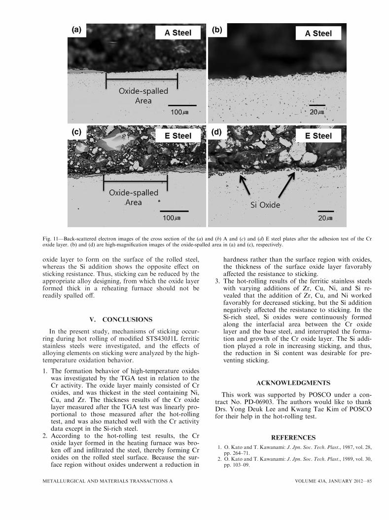
area 3 mm2) was bonded to the surface oxide layer byepoxy adhesives, the oxide layer was separated from thebase steel by pulling the aluminum stud. When theseparation occurred, the load was measured and aver-aged after the three-time tests. The adhesive strengths
are 10.6 MPa and 4.22 MPa in the A and E steels,respectively. After the oxide layer was separated, theremaining base steel was sectioned, and the cross-sectional area was observed by an SEM as shown inFigures 11(a) through (d). In the A steel, the surface of
Fig. 9—EDS mapping data of the oxide layer formed after the TGA test of the (a) A and (b) E steels.
METALLURGICAL AND MATERIALS TRANSACTIONS A VOLUME 43A, JANUARY 2012—83
the base steel is exposed as the Cr oxide layer is removedfrom the surface (Figures 11(a) and (b)). In the E steel,however, Si oxides are retained in the base steel becausethe interface between the Si oxides and the Cr oxidelayer is separated and the Cr oxide layer is spalled out(Figures 11(c) and (d)). This finding implies that theadhesive strength between the Si oxides and the Cr oxidelayer in the E steel is much lower than the adhesivestrength between the Cr oxide layer and the base steel inthe A steel. These adhesive test results agree well withthe results of Bamba et al.,[19] in which the adhesiveforce between the Cr oxide layer and the base steeldecreased as the Si content increased in Fe-15Cr steels.Thus, the Cr oxide layer is thinly formed in the E steel,and the Cr oxide layer is readily spalled off from thesurface during the rolling test (see the spallation ratiodata in Table V) because of the bad adhesive strengthbetween the Cr oxide layer and the base steel.
As mentioned earlier, the high-temperature oxidationbehavior, Cr activity calculation, and hot-rolling processwere investigated on five different kinds of stainlesssteels with varying contents of Zr, Ni, Cu, and Si, fromwhich the effects of alloying elements on sticking aresummarized as follows:
(a) Effect of Zr addition: The effects of alloying ele-ment Zr added to the stainless steels can be ana-lyzed by comparing the A and D steels. As shownin Table V, the D steel with a small addition of Zr
shows a thicker oxide layer than the A steel. In thetwo steels, the spallation of oxides occurs as therolling passes proceed, but the oxide layer formedbefore and after the rolling test is thicker in the Dsteel. When considering the beneficial effect of athick oxide layer on sticking, Zr has a good effecton reducing sticking even though a small amount(0.02 wt pct) was added to the D steel.
(b) Effect of Cu addition: By comparing the B and Csteels of Table I, the effects of 0.4 wt pct Cu addi-tion is investigated. According to the hot-rollingtest results, the oxide layer is thicker in the C steelthan in the B steel. After the second pass, theoxide layer remains uniform on the surface of theC steel, whereas it remains thin in the B steel. Thisimplies that the Cu addition positively affects thereduction in sticking.
(c) Effect of Ni addition: The effect of Ni addition canbe evaluated by comparing the C and D steels.After the first pass, the oxide layer is thicker in theD steel than in the C steel, whereas the spallationratio is lower. After the second pass, the oxidelayer thickness of the D steel is similar to that ofthe C steel as the spallation takes place more inthe D steel, and finely fragmented oxides are uni-formly distributed on the surface in both steels.Although oxides are formed more often in the Dsteel in the heating furnace, the amount of oxidesremained after the second pass is similar in bothsteels, as oxides are broken and spalled off fromthe surface. Thus, the Ni addition favorably influ-ences the reduction in sticking, but its effect is notlarge.
(d) Effect of Si addition: To investigate the effect of Siaddition on sticking, the A and E steels should becompared. The TGA and hot-rolling results indi-cate that the oxide layer is thinner in the E steelcontaining 0.5 wt pct Si than in the A steel. Asmentioned earlier, in the E steel, Si oxides areformed along the interfacial area between the Croxide layer and the base steel, and prevent the for-mation and growth of the Cr oxide layer. In addi-tion, as shown in the adhesive test results(Figures 11(a) through (d)), the formation of Sioxides deteriorates the bonding of the Cr oxidelayer and the base steel, and readily leads to thespallation of Cr oxides during hot rolling. Becausethe hardness of the surface region without oxidesis significantly lower than that of the surfaceregion with oxides, parts of the rolled steel can bebroken off by the rolls. The Si addition plays arole in increasing sticking, and thus, the reductionin Si content is desirable for preventing sticking.
Because the rolling test using a pilot-plant-scalerolling machine is a good way to identify stickingphenomenon occurring in actual hot-rolling stands, itcan be useful to understand mechanisms of sticking andto suggest desirable alloy-designing conditions for pre-venting or minimizing sticking. The resistance to stick-ing is enhanced by adding Zr, Cu, and Ni to ferriticstainless steels because these elements help the thick
Fig. 10—Schematic illustration showing the formation and growthof Cr oxides (Cr2O3) and Si oxides (SiO2) in the E steel.
84—VOLUME 43A, JANUARY 2012 METALLURGICAL AND MATERIALS TRANSACTIONS A
oxide layer to form on the surface of the rolled steel,whereas the Si addition shows the opposite effect onsticking resistance. Thus, sticking can be reduced by theappropriate alloy designing, from which the oxide layerformed thick in a reheating furnace should not bereadily spalled off.
V. CONCLUSIONS
In the present study, mechanisms of sticking occur-ring during hot rolling of modified STS430J1L ferriticstainless steels were investigated, and the effects ofalloying elements on sticking were analyzed by the high-temperature oxidation behavior.
1. The formation behavior of high-temperature oxideswas investigated by the TGA test in relation to theCr activity. The oxide layer mainly consisted of Croxides, and was thickest in the steel containing Ni,Cu, and Zr. The thickness results of the Cr oxidelayer measured after the TGA test was linearly pro-portional to those measured after the hot-rollingtest, and was also matched well with the Cr activitydata except in the Si-rich steel.
2. According to the hot-rolling test results, the Croxide layer formed in the heating furnace was bro-ken off and infiltrated the steel, thereby forming Croxides on the rolled steel surface. Because the sur-face region without oxides underwent a reduction in
hardness rather than the surface region with oxides,the thickness of the surface oxide layer favorablyaffected the resistance to sticking.
3. The hot-rolling results of the ferritic stainless steelswith varying additions of Zr, Cu, Ni, and Si re-vealed that the addition of Zr, Cu, and Ni workedfavorably for decreased sticking, but the Si additionnegatively affected the resistance to sticking. In theSi-rich steel, Si oxides were continuously formedalong the interfacial area between the Cr oxidelayer and the base steel, and interrupted the forma-tion and growth of the Cr oxide layer. The Si addi-tion played a role in increasing sticking, and thus,the reduction in Si content was desirable for pre-venting sticking.
ACKNOWLEDGMENTS
This work was supported by POSCO under a con-tract No. PD-06903. The authors would like to thankDrs. Yong Deuk Lee and Kwang Tae Kim of POSCOfor their help in the hot-rolling test.
REFERENCES1. O. Kato and T. Kawanami: J. Jpn. Soc. Tech. Plast., 1987, vol. 28,
pp. 264–71.2. O. Kato and T. Kawanami: J. Jpn. Soc. Tech. Plast., 1989, vol. 30,
pp. 103–09.
Fig. 11—Back-scattered electron images of the cross section of the (a) and (b) A and (c) and (d) E steel plates after the adhesion test of the Croxide layer. (b) and (d) are high-magnification images of the oxide-spalled area in (a) and (c), respectively.
METALLURGICAL AND MATERIALS TRANSACTIONS A VOLUME 43A, JANUARY 2012—85
3. O. Kato, S. Uchida, and T. Kimuma: Seitetsu Kenkyu, 1989,vol. 335, pp. 35–42.
4. T. Nakanishi: J. Soc. Tribol. Lubr. Eng., 1993, vol. 49, pp. 365–70.5. S. Uchida, H. Yamamoto, M. Akata, K. Watanabe, and O. Kato:
What’s New in Roll Technologies of the World, Report of ResearchCommittee on Rolling Roll, ISIJ, Tokyo, Japan, 1995, p. 183.
6. W. Jin, J.Y. Choi, and Y.Y. Lee: ISIJ Int., 1998, vol. 38, pp. 739–43.
7. W. Jin, J.Y. Choi, and Y.Y. Lee: ISIJ Int., 2000, vol. 40, pp. 789–93.
8. J.K. Kim, S.G. Hong, K.B. Kang, and C.Y. Kang: Met. Mater.Int., 2009, vol. 15, pp. 843–49.
9. D.-C. Wen: Met. Mater. Int., 2009, vol. 15, pp. 365–72.10. S. Lee, D. Suh, S. Oh, and W. Jin: Metall. Mater. Trans. A, 1998,
vol. 29A, pp. 696–702.11. C.-Y. Son, C.K. Kim, D.J. Ha, S. Lee, J.S. Lee, K.T. Kim, and
Y.D. Lee: Metall. Mater. Trans. A, 2007, vol. 38A, pp. 2776–87.12. D.J. Ha, Y.J. Kim, J.S. Lee, Y.D. Lee, and S. Lee: Metall. Mater.
Trans. A, 2009, vol. 40A, pp. 1080–89.13. S. Kim, S. Lee, K. Han, S. Hong, and C. Lee: Met. Mater. Int.,
2010, vol. 16, pp. 483–88.14. D.-C. Wen: Met. Mater. Int., 2010, vol. 16, pp. 13–19.15. J.L. Cavazos: Mater. Charact., 2006, vol. 56, pp. 96–101.16. E.E. Oguzie, J. Li, Y. Liu, D. Chen, Y. Li, K. Yang, and F. Wang:
Electrochim. Acta, 2010, vol. 55, pp. 5028–35.17. M. Vardavoulias and G. Papadimitriou: Mater. Lett., 1996,
vol. 27, pp. 349–53.
18. S.-T. Kim and Y.-S. Park:Met. Mater. Int., 2009, vol. 15, pp. 221–30.
19. G. Bamba, Y. Wouters, A. Galerie, F. Charlot, and A. Dellali:Acta Mater., 2006, vol. 54, pp. 3917–22.
20. D.J. Ha, H.K. Sung, S. Lee, J.S. Lee, and Y.D. Lee: Mater. Sci.Eng. A, 2009, vol. A507, pp. 66–73.
21. H.E. Kadiri, R. Molins, Y. Bienvenu, and M.F. Horstemeyer:Oxidation Metals, 2005, vol. 64, pp. 63–97.
22. H.E. Kadiri, R. Molins, Y. Bienvenu, and M.F. Horstemeyer:Oxidation Metals, 2005, vol. 64, pp. 99–117.
23. N. Birks and G.H. Meier: Introduction of High Temperature Oxi-dation of Metals, Edward Arnold, London, UK, 1983, p. 80.
24. H.G. Jung, J.K. Ahn, and K.Y. Kim: J. Kor. Inst. Met. Mater.,2001, vol. 39, pp. 1032–40.
25. B. Sundman, B. Jansson, and J.-O. Andersson: CALPHAD, 1985,vol. 9, pp. 153–90.
26. B.-J. Lee and B. Sundman: TCFE2000: The Thermo-Calc SteelsDatabase, KTH, Stockholm, Sweden, 1999, pp. 2–81.
27. K.G. Chin, H.J. Lee, J.H. Kwak, J.Y. Kang, and B.J. Lee:J. Alloys Compd., 2010, vol. 505, pp. 217–23.
28. F.H. Stott and F.I. Wei: Oxidation Metals, 1989, vol. 31, pp. 369–75.
29. O. Kubashewski and B.E. Hopkins: Oxidation of Metals andAlloys, Butterworths Scientific Publications, London, UK, 1962,p. 173.
30. F. Velasco, A. Bautista, and A. Gonzalez-Centeno: Corr. Sci.,2009, vol. 51, pp. 21–27.
86—VOLUME 43A, JANUARY 2012 METALLURGICAL AND MATERIALS TRANSACTIONS A