Embed Size (px)
Citation preview
http://repository.osakafu-u.ac.jp/dspace/
TitleEffects of Current on the Formation of Chromium-Nickel-Iron Alloys fro
m Trivalent Chromium Baths
Author(s) Ishihara, Akira; Hayashi, Tadao
Editor(s)
CitationBulletin of University of Osaka Prefecture. Series A, Engineering and nat
ural sciences. 1981, 29(2), p.83-93
Issue Date 1981-03-31
URL http://hdl.handle.net/10466/8333
Rights

83
Effect of Pulsed Current on the Formation of Chromium-Nickel-Iron
Alloys from Trivalent Chromium Baths
Akira ISHIHAMA* andTadao HAYASHI"'
(Received November 15, 1980)
' The infl'uence of the pulse pararneters (pulse current density, ayerage current
density and on-time) on composition and properties of Cr-Ni-Fe alloy deposits and glso
ChrOMIUM trivalenton current efficiency in the electrodeposition of the alloys from
baths was described. The alloys containing 18%Cr, 8%Ni and a balance of iron prepared by pulsedcurrent electrolysis had good corrosion resistance, high hardness and very smooth
surface. X-ray difftaction analysis revealed that the Cr-Ni-Fe alloy deposits obtained ip fhe
present study consisted of two kinds of solrd solutions over the entire alloy compositign
range. The Cr-Ni-Fe alloy deposits prepared by direct current electrolysis gave a dM
fraction line corresponding to solid solution (M-Fe, however, the alloy deposits obtaine.d
by pulsed current electrolysis had typical diffraction lines corresponding to an austenitic
stainless steel.
1. introduction
The electrodeposition of Cr-Fei) and Cr-Ni-Fe2) alloys from trivalent chromium baths
containing fbrmate and glycine has been reported in the previous papers, and factors
affecting alloy composition, mechanism of alloy deposition and characteristics of the alloy
deposits have been discussed in de.tail.
A general survey on the electrodeposition of metals by pulsed current has been reported
by ib13). The pulsed current electrodeposition of copper has been discussed by Linfbrd et
al.4'6), and by Hayashi et al.78).
Ibl et al.9) have shown that favorable effects could be obtained by using short pulses
with large current density, fbllowed by off・time which is sufficiently long to allow complete
relaxation of diffusion layers. Viswanathan and RaublO) have shown that nickel deposits
obtained by pulsed current electrolysis were less porous than those obtained by direct
current. Sun et al.11) have reported that the increase in duty cycle in pulsed current electro-
lysis led to the decrease in the surface roughness of the metal deposits.
Theoretical treatment of the pulsed current electrolysis have also been discussed by
Cheh et al.i2'i5) and also by Ibl et al.9).
Viswanathan and Raubl6) showed that the composition of Au-Ni alloys electrodeposited
from an alkaline cyanide bath were independent of pulse current density. On the other
hand, Reid et al.17), Branik and Schnabl18) and Stimetz and Hren19) reported that some
`
" Graduate student, Department of Applied Chemistry, College of Engineering.
** Department of Applied Chemistry, College of Engineering.

84 Akira IsHIHAMA and Tadao HAYASHI
properties of Au-Co alloy deposits were improved by pulsed current electrolysis.
Therefore, pulse parameters (pulse current density, on-time and offLtime) seem to give
many possibilities, viz., to create a variety of mass transport situations and electrodeposition
conditions and also a variety of adsorption and desorption phenomena during on- and
off・time. It might also be possible to obtain metal deposits superior to those obtained by
usual direct current electrolysis.
In order to investigate the effect of pulse parameters on the properties of Cr-Ni-Fe
alloy deposits, square galvanostatic pulses were examined in the present study. The para-
meters are on-time, off・time and pulse current density: The compositionofthe alloydeposits
and the current efficiency fbr deposition of each metals have been analyzed as a function of
pulse parameters. The surface morphology, the corrosion resistance, the structure and
hardness of the alloys obtained by pulsed current and direct current were compared.
2. Experimenta1
2-1 . Composition of bath and plating conditions
Electrolytes for the electrodeposition of Cr-Ni-Fe alloys were prepared from special-
grade chemicals and deionized water. Trivalent chromium baths containing O.6 M CrC13,
O.05 M NiC12, O.2 M FeC12, O.6-1.8 M HCOONa, O.2-O.7 M NH2CH2COOH, O.15 M
NH4Br, 1 M NH4Cl and O.6 M H3B03 which were kept at 300C, pH 2.8 and without agi-
tation, have been used. The electrodeposition of alloys was perfbrmed using a platinum
cathode for determining the composition of alloy deposits and the current efficiency. A
copper disk electrode was also used as a cathode for evaluating deposits. Insoluble graphite
anodes were separated with sintered glass diaphragms to avoid contaminating the solution
with anode products.
The instantaneous current and duty cycle were determined by an oscMoscope. The
average current density (i,) was calculated from the frequency of pulsed currents, which
were also measured with the oscruoscope.
A commercial pulse generator supplied pulses with 1 to 100 msec duration and the
current up to 3 A. In order to examine the electrode process in much shorter duration, we
used another pulse generator which supplied pulses with O.1 to 100 msec duration, and
the current up to O.5 A.
The average current density (i.) in pulsed current electrolysis is defined as '
Ti =i 'a p T+ T' '
(1)
where, ip = pulse current density, T = ontime and T' = offtime.
The duty cycle (D) under pulsed condition is defined as
T D= T.T, ・100(%). (2)
Effect offulsed Cberrent on the ]Fbrmation of ChromiumrNickel-fron Alloys from 7}ivalent ChromiumBaths 85
2-2. Composition of alloy deposits and current efficiency
The ailoy deposits plated on platinum cathodes were dissolved in conc. HCI solution
and the chromium, nickel and iron contents were then analyzed by an atomic absorption
spectrometer. The cathode current efficiency was calculated from the weight of the de-
posits, the composition of alloys and the quantity of electricity used for the electrolysis.
The surface morphology of the alloy deposits plated on a compper substrate was
examined by an optical microscope.
2-3. Corrosion resistance and hardness
The alloy deposits plated on a platinum wire cathode were anodically polarized in a
O.1 M Na2S04 solution with a sweep rate of 40 mV/min in the potential range of - O.6 to
2.0 V vs. SCE. Before each experimental run, the solution was deaerated with Argon.
The corrosion current and corrosion potential of the alloy deposits were estimated by
analyzing ・the Tafe1 plots in the anodic and cathodic polarization curves in a O.05 M H2 S04
solution at 300C.
X-ray diffraction analysis of the alloy deposits obtained from the fbrmate-glycine bath
under various conditions was carried out using X-ray difftactometer with Fe-Ka radiation.
The hardness of the alloy deposits (ca. 30 ptm) was measured by the micro-Vickers
hardness tester (Shimadzu seisakusho Ltd., Type M) using a load of 50 g.
3. Resultsanddiscussion
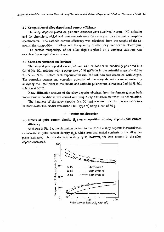
3-1. Effects of pulse current density (ip) on composition of alloy deposits and current
efficiency As shown in Fig. 1a, the chromium content in the Cr-Ni-Fe alloy deposits increased with
an increase in pulse current density (ip), while iron and nickel contents in the alloy de-
posits decreased. With a decrease in duty cycle, however, the iron content in the alloy
deposits increased.100
sA80t't..M
60oqoVhg 4o
Eie-g 20g・ o
q Sxq s .-O""N N"l:L'
O Fe
A Cr
N Ni
"'--o....N---- -----::----------------------
------duty cycle 5
---- duty cycle 20
------- duty cycle 50
kw;-:pt;3-;S;SS-
-'8
iyf-r-(?
ut..--6
...,.,.
o 100Pulse current density, ip (A/dm2)
200
'
86 Akira ISHIHAMA and Tadao HAYASHI
80
-70
60
50,
..KsvE},= 40.9.9'
asE 3o
g
20
10
o
O Fe
ACr duty cycle 20ONi ---duty cycle 50e Alloy'
er-'-"e><(eN
× × eN ×
Nx No. NNNN...N.. O
No AA-, tt--A- "" "" -..NNN
ttbr"'
fi--[p---u---"]
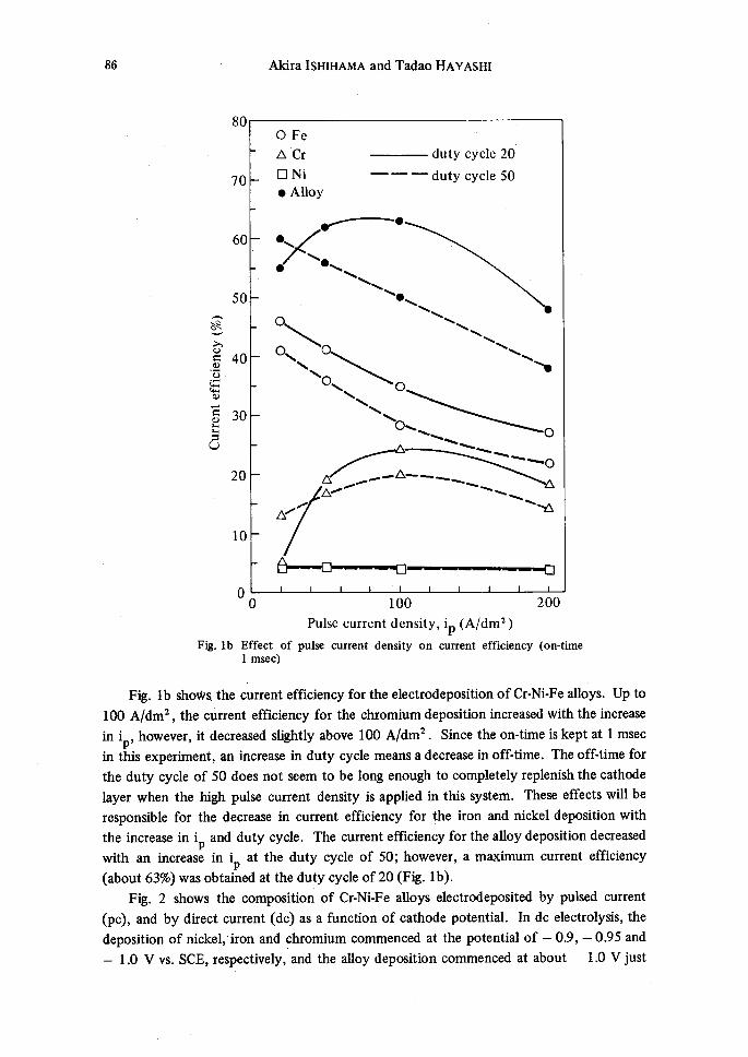
Fig. Ib
o
Effect
1 msec)
1OO Pulse current density, ip (A/dm2 )
of pu4se current density on current efficiency
200
(on-time
Fig. Ib shoWs the current efficiency for the electrodeposition ofCr-Ni-Fe alloys. Up to
1co A/dm2 , the ctirrent efficiency for the chromium deposition increased with the increase
in ip, however, it decreased slightly above 100 A/dm2. Since the on-time is kept at 1 msec
in this experiment, an increase in duty cycle means a decrease in off:time. The off・time for
the duty cycle of 50 does not seem to be long enough to completely replenish the cathode
layer when the high pulse current density is applied in this system. These effects will be
responsible for the decrease in current efficiency for the iron and nickel deposition with
the increase in ip and duty cycle. The current efficiency forthe alloydeposition decreased
with an increase in ip at the duty cycle of 50; however, a maximum current efficiency
(about 63%) was obtained at the duty cycle of 20 (Fig. Ib).
Fig. 2 shows the composition of Cr-Ni-Fe alloys electrodeposited by pulsed current
(pc), and by direct current (dc) as a function of cathode potential. In dc electrolysis, the
deposition of nickel,'iron and ghromium commenced at the potential of - O.9, - O.95 and
- 1.0 V vs. SCE, respectively, and the alloy deposition commenced at about - 1.0 Vjust

Ell!reet ofPttlsed Current on the llormation of ClhromiumTiVickel:fron Allays from 77ivalent CJiromiumBaths 87
befbre the chromium deposition.
contents in the alloys decreased,
100
.-
S 80:-'6-
g 6o
vta£re
ts 40.s
'6-g 2o
U
o
With the increase in cathode potential, the iron and nickel
whereas the chromium content in the alloys increased.
ONOXX, $'"
O.-.. 'X -- No Fe
AaaNi
dc
--duty cycle 5
o-o
k:#>si
・duty cycle 10
duty cycle 20duty cycle 50
N.-..t・;;41
f¢.2tt..,tf..
--i -an-"-m -O.8 -1.0 -1.2 -1.4 -1.6 -1.8 Potentia1 (Vvs. SCE)
Ftg. 2 Composition of Cr-Ni-Fe alloy deposits as a function of cathode
potential (on-time 1 msec)
In the potential range of - 1.4 to - 1.7 V, the composition of alloys was found to be
nearly constant. The chromium content in the alloys obtained by the pc electrolysis was
found to be smaller than that obtained by the dc electrolysis, whereas the iron content was
greater than that obtained by the dc electrolysis. With an increase in duty cycle the com-
position of alloy deposits approached to that obtained by dc electrolysis. These results
showed that a higher duty cycle gave rise to the same condition encountered in dc electro-
lysis.
In general, metals and alloys having a fine structure would be electrodeposited by pc
electrolysis. The surface microstructure of the Cr-Ni-Fe alloys electrodeposited by pc
electrolysis at ip of20 and 100 A/dm2 is shown in Figs. 3a and 3b,respectively. At relatively
low ip, a granular surface similar to the alloy deposits obtained by dc electrolysis, was
observed. However, at a high ip (100 A/dm2) a few granular growth was observed on the
smooth surface.
waew
(a) ip 20, i. 10 Aldm2
Fig. 3 Photomicrographs of Cr-Ni-Fe alloy deposits prepared by pc electrolysis

88 Akira ISHIHAMA and Tadao HAyASHI
The Cr-Ni-Fe alloy deposits obtained by pc electrolysis were found to be more uniform
and bright than those obtained by dc electrolysis.
3-2. Effects of average current density (i.)
Fig. 4a shows, the efTect of average current density (i.) on the chromium and nickel
contents in the alloy deposits. The chromium content in the alloys increased with the
increase in i,, while the nickel content shghtly decreased. Therefbre, the iron content
decreases with the increase in i.. When ip was small (20 A/dm2), the composition of alloy
deposits was similar to that obtained by dc electrolysis. In the relatively low i. range, with
increasing ip the chromium content was found to become higher than that obtained by dc
electrolysis. However, it may be noted that the dependence of the composition of alloys on
i. is not significant at high ip values. Therefore,the Cr-Ni-Fe alloy films of the unifbrm
composition may be formed even on a complexly shaped article, if high ip values were
employed.
50
A8" 40)v.m'O-.
g 3oggE 2oie-
g io
8
o
A Cr
O Ni
- - ----"-------"-
------------
dcip 20 A/dm2
ip 50 A/dm2
ip 100 A/dm2
ip 200 A/dm2
--t2r-"-"" ! ...br" .tlir' '-'-A .-AF l: lt・1:..xl.[:. A-,A
Zbe-'- ...-.A・"" ......A"-."--'
----
1 2 5 10 20 50 100 Average current density, ia (A/dm2)
Fig. 4a Effect of average current density on composition of Cr-Ni-Fe alloy
deposlts (on-time 1 msec)
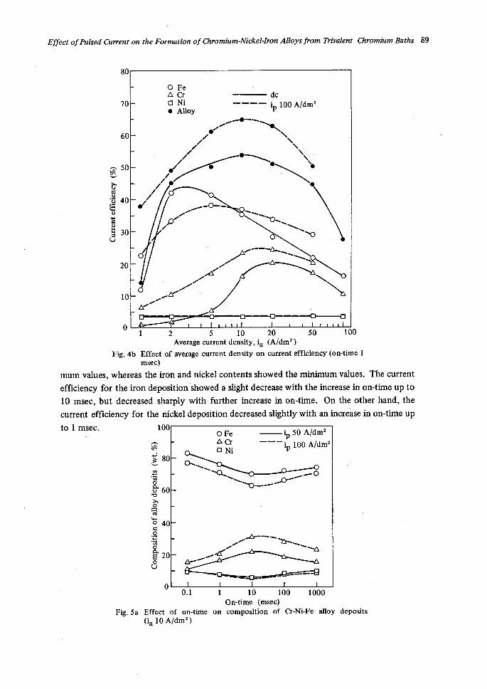
Fig. 4b shows the eikct of i, on current efficiency. The current efficiency for the
deposition of each metals in pc electrolysis was found to be higher than that obtained in dc
electrolysis. Thus, the Cr-Ni-Fe alloys were electrodeposited with a htgher current efficiency
in pc electrolysis. The alloy deposits, having 18%Cr, 8%Ni and a balance of Fe, were ob-
tained by pc electrolysis with the current efficiency of 65%, compared to 53% in dc
electrolysis.
3-3. Effects of on-time on composition of alloy deposits and current efficiency
Figs. 5a and 5b show the effect of on-time on the composition of alloy deposits and
current efficiency in the electrodeposition of Cr-Ni-Fe alloys. At about 10 msec on-time,
the chromium content and the current efficiency fbr chromium deposition showed maxi-
ElliXeet ofPUIsed Cletrrent on the Iibrmation of enromium-Alickel:fron Alloys from 7)ivalent CIEiromiumBaths 89
80
70
60
A 50gev,
h8・g 4o
Eo12ts 30
U
20
10
!/
O FeA Crn Nie AllQy
/Ze
/-1!-"
e
---- ..e-s-t
e
dc ip 100 A/dm2
× Nx N el
/C.)Z-gX8NNN .,Q-
o
-AZAr/tAr/-
NON Nx s
/tl-"tt'N9Xx
----M-"E--" o 1 2 5 10 20 50 100 Average current density, ia (Aldm2)
Fig. 4b Effect of ayerage current density on current efficiency (on-time 1
msec)mum values, whereas the iron and nickel contents showed the minirnum values. The current
efficiency fbr the iron deposition showed a slight decrease with the increase in on-time up to
10 msec, but decreased sharply with further increase in on-time. On the other hand, the
current efficiency for the nickel deposition decreased slightly with an increase in on-time up
to 1 msec. 100
.-
}' 80:.
'g.8 6o
st
: 40ie--8g 2ooo
o
ctNN
OFe-A CrO Ni
lp 50 Aldm2
--' ip lOO AIdm2
Ar.t
sc<NN.v-p..D.--O
-tr
/A-----tz"....
- N-.tN"...-.---
Ftg. 5a
O.1
Effect of on-time(ia 10 A/dm2)
1 10 100 1000 On-time (rbsec)
on composition of Cr-Ni-Fe alloy deposits

90 Akira IsHIHAMA and Tadao HAYASHI
70
60
50
dvA
vb 40g'5ato 30Ge6 20
10
o
O FeA Cro Nie Alloy
/eA'xxx e
ox/./A-xxillXlllllllr.
aA----'O'-----o-----oO.1 110
On-time
100(rnsec)
1OOO
Fig. 5b Effect ofon-time on current efficiency (ip 100, ia 10 A/drn2)
If the on-tkne is equal to the so-called transition time, the interfacial concentration of
the metal ions (C,) may drop to zero at the end of the pulse and the current efficiency fbr
the metal deposition decreases. Usually, the transition time T is determined by the fbllowing
equation (3).
T = (ZF)2Co2D/2ip2
Where,z =
F= Co =
D=
number of electrons transferred
Faraday's constant
bulk concentration of metal ion
diffusion coefficient of metal ion
(3)
Solving T for each metal deposition by using the equation (3), r fbr the deposition of
chromium, nickel and iTon was fbund to be about 200, O.7 and 10 msec, respectively at the
ip of 100 Aldm2. In Fig. 5b, fairlygood coincidence could be found between the transition
time and the on-time at which the current ethciency decreased. This result suggests that the
electrodeposition of Cr-Ni-Fe alloys may be controlled by the mass transfer.
With an increase in on-time, the surface of the alloy deposits became simi1ar to that
obtained by dc electrolysis, i.e. the granular growth was observed on the surface.

Efilect ofPtzlsed Cberrent on the ilormation of thromium:iVickel-fron Alloys from 7)ivalent thromiumBathS 91
34. Corrosion reslstance
The corrosion resistance of the electrodeposited metals and alloys can be evaluated by
measuring the anodic polarization curves in acid or neutral solution20) .
As mentioned previously, the anodic polarization curves were measured in a O.1 M
Na2S04 solution (pH 6.0, 300C), fbr the Cr-Ni-Fe alloy deposits prepared by dc and pc
electrolysis. The anodic polarization curves are shown in Figs. 6a, 6b and 6c. All the
ailoy deposits gave the typical active and passive stages in the anodic polarization curves,
as shown in Fig. 6. The active peak and also passive current ofthe alloys decreased with an
increase in chromium content in the alloy deposits. The values of the active peak and
passive current for the Cr-Ni-Fe alloys prepared by pc electrolysis were found to be smaller
than those of the alloys prepared by dc electrolysis.
lo2
1 10:
E
qse loo,b.
g・E io-i
e
IO
h ss Nxe,i,""'<l".,,M
"
E
- dc,7.5A/dm:
.".-. ip 20, ia 7
-- ip 50, ia 20
lo2
lol
loO
lo'1
t
vi i'
t-
T':k"r<:-・li
- dc,15A/dm2-----
ip 50, ia 25
-- ip 100, ia 8
lo2
lol
loO
lo'1
'2 o +i.o +2.o iO'2 o +i.o +2.o iO-2 o +i.o +zo Potential (Vvs.SCE) Potential (vvs, scE) Potential <Vvs.SCE)
(a) , <b} (c) Anodic polarization curves for Cr-Ni-Fe alloy deposits in O.1 M NaiS04 solution (30" C)
il it tl i't ,"7
7t""'N
gs'
iVg-/('A;,d7g
-- ip 200, i, 1Ol
Fig・ 6,,
The parameters associated with the anodic polarization of the electrodeposited Cr-Ni-Fe
alloys, estimated from the present study are summarized in Table 1 . The corrosion current
of the alloy deposits in O.05 M H2S04 solution decreased with an increase in the chromium
cbntent in the alloys.
Table l Icorr,Ecorr and miero-Vickers hardness of alloy deposits
Plating condition
C.D. (A/dm2)
Composition of alloys (%)
Cr Ni Fe Icorr(mA/dm2 )
Ecorr(V vs.SCE)
Hv
dc 7.5pc ip 20, ia 10
dc 15pc ip 100, i. 8
dc 30pc ip 100, i, 15
13
13
18
18
24
24
8
8
8
8
8
8
79
79
74
74
68
68
10.0
3.2
025
O.17
O.35
O.05
-O.57
-O.58
-O.35
-O.48
-O.56
-O,56
452
503
440
453
404
414

92 Akira IsHIHAMA and Tadao HAYASHI
In general, the alloy deposits prepared by pc electrolysis seemed to give lower corrosion
currents compared to the same type of the alloy deposits obtained by dc electrolysis.
3-5. Stucture and hardness of alloy deposits
X-ray diffraction analysis of the electrodeposited Cr-Ni-Fe alloys revealed that they
consisted of two kinds of solid solutions over the entire composition range of the alloys.
In the X-ray diffraction patterns of the as-plated alloys obtained by dc electrolysis, two
typical difftaction lines, which correspond to Fe(OH)2 (2e = 49.70) and a-Fe (2e = 57.60),
were observed. After annealing the same deposits at 2000C for one hour, the line of a-Fe
sharpened. After heating the same alloys at 6000C for one hour,they showed two additional
peaks at 55.80 and 65.30 2e (denoted 7 in Fig. 7) which are characteristics of an austenitic
18%Cr-8%Ni stainless steel.
pt
A= oo tu
tue
>a)
pt
A=ovm
£8
b)
Oine
>
c)
45 50 55 60 65 70
Ftg. 7 X-ray diffraction patterns of Cr-Ni-Fe alloy deposits
[gl Pdg;IR;'AO/Od,lii8,.A,f,d,m.,},・as-plated
(c) dc, 15 A/dm2,heat treated at 600eC for one hr
On the contrary, the same 18%Cr-8%Ni-Fe alloys obtained by pc electrolysis gave a
weaker peak for Fe(OH)2, and those corresponding to a-Fe were rnore pronounced. Even
in the as-plated condition, the alloy containing 18%Cr-8%Ni or 24%Cr-8%Ni showed the
diffiraction 1ines corresponding to the austenitic stainless steel, as shown in Fig. 7. The
hardness of the alloy deposits obtained by pc as well as dc electrolysis are also tabulated in
Table 1.
At the same composition, the alloy deposits prepared by pc electrolysis had a higher
hardness as compared to those prepared by dc electrolysis.
'
EltTect ofPbelsed Cbei:rent on the formation of ClhromiumrArickql:llron AllQys from 7)'ivalent ChromiumBaths 93
The higher hardness of the alloys obtained by pc electrolysis might be attributed to the
decrease in the content of non-metallic materials, such as Fe(OH)2. These compounds
may be accumulated at the cathode surface during the electrolysis, since hydrogen de-
position is always observed. Such materials can also be diffused away from the cathode
surface during the offLtime in pc electrolysis, which can not be expected in dc electrolysis.
References
1)
2)
3)
4)
5)
6)
7)
8)
9)
10)
11)
12)
13)
14)
15)
16)
17)
18)
19)
20)
T. Hayashi and A. Ishihama, Plating and Surface Finishing, 66 (9), 36 (1979)
A. Ishihama and T. Hayashi, ftoc. 10th World Congress on Metal Finishing, p.118 (1980)
N. Ibl, Surface Technology, 10, 81 (!980)
H.Y. Cheh, H.B. Linfbrd and C.C. Wan, Plating and Surface Finishing, 64 (5), 66 (1977)
H.Y. Cheh, P.C. Andricacos and HB. Linfbrd, ibid., 64 (7), 42 (1977)
P.C. Andricacos, H,Y. Cheh and H.B. Linford, ibid., 64 (9), 44 (1977)
M. Yokoi and T. Hayashi, DENKI KAGAKU, 46, 195 (1978)T: Hayashi and M. Yokoi, ibrd., 47, 654 (1979)
N. Ibl, J.Cl. Puippe and H. Angerer, Surface Techhology, 6, 287 (1978)
M. Viswanathan and Ch.J. Raub, Galvanotechnik, 66, 277 (1975)
T.P. Sun, C.C. Wan and Y.M. Sky, Metal Finishing, 77 (5), 33 (1979)
・H.Y. Cheh, J. Electrochem. Soc., 118, 551 (1971)H.Y. Cheh, ibid., 118, 1132 (1971)
K. Viswanathan, M.A.F. Epstein and H.Y. Cheh, ibrd., 125, 1772 (1978)
C.C. Wan, H.Y. Cheh and H.B. Linford, J. AppL EIectrochem., 9, 29 (1979)
K. Viswanathan and Ch.J. Raub, Surface Technology, 4, 339 (1976)
F.H. Reid, P.A. MaUsli and S.G. Steineman, Plating and Sunhce Finishing, 67, 62 (1980)
M. Branik and R. Schnabl, Proc. International Pulse Plating Symposium (1979)
C.J. Steimetz and J.J. Hren, ibid. (1979)J.M. Sykes and G.P. Rothwell, Trans. Inst. Metal Finishing, 55, 155 kl977)
,