Embed Size (px)
Citation preview

Research Report
EFFECTS OF HEAD SIZE ON THE
PERFORMANCE OF TWIST-OFF BOLTS
by
Keith O. Schnupp Graduate Research Assistant
and
Thomas M. Murray, Ph.D., P.E.
Principal Investigator
Submitted to
Unytite, Incorporated One Unytite Drive Peru, Illinois 61354
Report No.
May 2003
Structures and Materials Research Laboratory The Charles E. Via, Jr. Department of Civil and Environmental Engineering
Virginia Polytechnic Institute and State University

i
TABLE OF CONTENTS
CHAPTER PAGE
1. PURPOSE......................................................................................................... 1
2. PREVIOUS RESEARCH................................................................................. 2
3. DESCRIPTION OF BOLTS ............................................................................ 6
4. TEST SETUP AND PROCEDURE................................................................. 8
5. EXPERIMENTAL RESULTS ....................................................................... 11
5.1 Overview........................................................................................................ 11 5.2 Results for F1852/A325 Strength, Centered Bolts ........................................ 11 5.3 Results for A490 Strength, Centered Bolts.................................................... 13 5.4 Results for F1852/A325 & A490 Strength, Off-Centered Bolts.................... 16
6. CONCLUSIONS ............................................................................................ 18
7. REFERENCES............................................................................................... 20
APPENDIX PAGE
A BOLT INSPECTION CERTIFICATES......................................................... 21
B GRAPHICS OF BOLT AND PLATE LAYOUTS ........................................ 31
C TEST RESULTS FOR F1852/A325 STRENGTH BOLTS........................... 35
D TEST RESULTS FOR A490 STRENGTH BOLTS ...................................... 45
E PHOTOS TAKEN DURING TESTING ....................................................... 53

ii
LIST OF TABLES
TABLE PAGE
3.1: Average Head Diameters for Supplied F1852/A325 & A490 Strength Bolts, and F436 Washer Diameters ............................................................................... 6
4.1: Test Matrix with Bolts Centered in Holes........................................................... 9
4.2: Test Matrix with Bolts Placed to One Side of Hole.......................................... 10
LIST OF FIGURES FIGURE PAGE
3.1: Photo of Manufacturer's Standard and F1852 Minimum Diameter 1-1/8" Bolts......................................................................... 7
4.1: Typical Skidmore Setup with Test Sample ....................................................... 10
5.1: F1852/A325 Strength, Centered Bolts, Standard Holes.................................... 12
5.2: F1852/A325 Strength, Centered Bolts, Oversized Holes.................................. 12
5.3: F1852/A325 Strength, Centered Bolts, Long-Slotted Holes ............................. 13
5.4: A490 Strength, Centered Bolts, Standard Holes ............................................... 14
5.5: A490 Strength, Centered Bolts, Oversized Holes ............................................. 14
5.6: A490 Strength, Centered Bolts, Long-Slotted Holes ........................................ 15
5.7: F1852/A325 Strength, Off-Centered Bolts........................................................ 16
5.8: A490 Strength, Off-Centered Bolts ................................................................... 17

1
EFFECTS OF HEAD SIZE ON THE
PERFORMANCE OF TWIST-OFF BOLTS
1. PURPOSE The head diameter of button-head type twist-off bolts necessary for adequate and reliable
performance has been brought into question. Following the RCSC Specification, F436
washers are not required under the bolt head when the bolt head diameter equals or
exceeds the diameter of a standard ASTM F436 washer, when used on oversized and
slotted holes. The same is true for A490 strength bolts that are used with steels that have
minimum specified yield strengths less than 40 ksi. The intent of this study was to
determine if the RCSC Specification should be modified to allow for ASTM F1852
minimum diameter twist-off bolts.
Minimum head diameters that are smaller than an ASTM F436 washer are allowed under
the ASTM F1852 specification. Some manufacturers produce twist-off bolts that have
head diameters that are larger than that required by ASTM F1852, but are less than the
ASTM F436 washer diameter. These diameters would be required to have a washer
under the bolt head on oversized and slotted holes if the current RCSC Specification was
followed.
The purpose of this research was to determine if bolts with ASTM F1852 minimum head
diameters are comparable to those with a diameter equal to or larger than an ASTM F436
washer. Testing was done on bolt diameters ranging from 5/8 in. to 1-1/8 in., including
both A325 and A490 strength bolts. Bolt heads having the minimum required diameter
permitted by ASTM F1852 were tested against those having larger head diameters.
Plates were used with various hole sizes including standard, oversized, excessively
oversized and slotted holes.

2
2. PREVIOUS RESEARCH Previous research dealing with twist-off bolts is very limited. Much of this work did not
deal specifically with the effects of bolt-head size on pretension forces. However, some
work is related to the findings contained in this report.
Research was conducted by Chesson and Munse in the early 1960’s at the University of
Illinois dealing with the effect of washers on the clamping force of 3/4 in. A325 bolts.
Regular and heavy semi-finished hexagon head bolts were used along with finished,
heavy, and flanged nuts. Hole sizes ranged from a standard 13/16 in. diameter hole to an
oversized hole of 7/8 in. diameter. The majority of the bolts were tightened using turn-
of-nut method. The tightening procedure involved snugging the bolt with an impact
wrench to approximately 5,000 pounds, then turning the nut or bolt head an additional
one-half turn. Bolts that were tightened with washers under the bolt head were compared
to those tightened without washers.
Test results showed that the presence of a washer under the bolt head had no significant
effect on the clamping or pretension force achieved in the bolts for all hole sizes. The
type and hardness of the nut had a greater effect on the clamping force than the washers.
The torque required to achieve the pretension forces measured was found to be higher for
the bolts without washers due to the galling of the nut into the soft plate material. Hole
size did not influence the achieved pretension by a significant amount. All clamping
forces on oversized holes without washers were well above the required minimum, and
comparable to the tests conducted on standard holes with washers. Long term relaxation
of the bolts forces was also studied and found that the inclusion or exclusion of washers
had no influence on relaxation. The major difference between the testing conducted by
the University of Illinois and the testing contained in this report deals with the kind of
bolts used and the method of tightening that was employed -- hexagon head bolts
compared to twist-off bolts and turn-of-nut procedure versus twist-off torque control.
Allan and Fisher performed studies on oversized and slotted holes in the late 1960’s.
They were primarily concerned with holes having larger clearances, above the 1/16 in.
and 1/8 in. tested by Chesson and Munse. Bolts of 1 in. diameter and A325 strength were

3
tested in hole sizes of 1/4 in. and 5/16 in. above the nominal bolt diameter and compared
against the standard 1/16 in. clearance. The bolts were installed with and without
washers using the turn-of-nut method. The results obtained were analyzed to observe the
effects of oversized and slotted holes had on achieved bolt pretension, bolt relaxation,
and joint slip resistance. The data was used to determine if washers should be required
under the bolt head.
Bolts tested in the 1-1/16 in. standard hole without washers were able to attain
pretensions well above the minimum, as shown in the previous tests by Chesson and
Munse. Bolts tested in the 1-1/4 in. oversized hole without washers had the same average
pretension as bolts tested with washers in the same hole size. These pretensions however
were slightly lower than those obtained in the 1/16 in. hole size. The increased hole size
increased galling around the hole in the test setups that did not include washers under the
bolt head. The 5/16 in. oversized holes required washers under both the head and nut to
attain the necessary pretension. The relaxation of the bolts was not affected by oversized
and slotted holes. Allan and Fisher also concluded that the slip coefficient for the 1-1/4
in. holes were comparable to the standard holes, however the coefficient decreased for
the 1-5/16 in. and slotted holes. Omitting washers from the 1-1/4 in. oversized hole did
not affect bolt pretension greatly but they were suggested to be used to prevent plate
galling.
Other research relating hole size and joint slip coefficients can be found in "Bolted
Connections with Varied Hole Diameters" by Shoukry and Haisch. Their tests involved
determining the effects oversized holes had on bolted connections. 3/4 in. and 7/8 in.
A325 bolts were used in butt and lap joints and were tightened using the calibrated
wrench and the turn-of-the-nut methods with washers only under the turned element.
Hole clearances ranged from 1/16 in. up to 1/4 in. Testing concentrated on the initial slip
of the joints which was needed for slip coefficient calculations. After this data was
collected, the specimens were loaded until failure to find the ultimate shear load and
shear stress of the joint. Results showed that the slip coefficients and ultimate shear
strengths of the joints were not significantly affected by hole clearances up to 3/16 in.
This is true for the 3/4 in. and 7/8 in. A325 bolts tested in the butt and lap joints.

4
More recent testing specifically with twist-off bolts was performed by Kulak and
Undershute in the late 1990’s, studying factors that affect the achievable pretension force
in twist-off bolts. They stated that, "Factors that affect the preload of a tension control
bolt are bolt material strength, thread conditions (such as lubrication, dirt, and thread
damage), the diameter of the annular groove at the splined end, and friction conditions at
the nut-washer interface." The main factors investigated included the effects of storage
and aging conditions as well as friction conditions on the achieved pretension force in the
bolt. Bolts of 3/4 in. diameter and A325 strength were received from seven different
manufacturers. These bolts were of different ages upon receipt and were purposely
subjected to different storage conditions prior to tightening. Some of these conditions
included sealing the bolts in a container for up to 4 weeks, fully exposing others to the
elements and subjecting additional bolts to humid environments. The friction tests
involved testing bolts with different lubrication arrangements.
All of the bolts in the storage tests were able to attain the required pretension force.
Sealing in containers and exposing to humidity had little effect on the ultimate
pretension. Average values for these were 16% to 20% higher than required. Full
exposure to weather, and weathered snugged bolts in a steel joint produced the lowest
pretension values, around 5% to 10% above that required. The friction tests revealed
how loss of lubrication on the assembly affects pretension values. These bolts were an
average of 20% below the required preload force. On the high end, bolts and washers
that were cleaned and relubricated resulted in a pretension 52% above required. The tests
performed by Kulak and Undershute show how important storage conditions and proper
lubrication is on the ultimate pretension force in twist-off bolts.
Research by Oswald, Dexter and Brauer dealt with large-diameter bolts and the effects of
grip length on pretension forces. Their work found that many 1 in. and 1-1/8 in. bolts
that had grip lengths longer than 7 in. were unable to attain the necessary preload
required. Shorter length bolts had no problem attaining this value. Reasons for the low
pretensions attained were stated as, "greater difficulty in snugging the plies in the
connections with the longer bolts and the very high pretension forces that the large-
diameter, high-strength bolts required to develop specified pretension stresses…". They

5
suggested that "designers should consider alternatives to the use of large diameter A490
bolts in slip-critical joints, especially if the bolts have a long effective bolt length (greater
than 178 mm or 7 in.) and are installed through more than one interface".
The research that is most related to this study is that performed by Chesson and Munse
and by Allan and Fisher. Both tests looked at the need for washers under the bolt head in
oversized holes. The main difference is the type of tightening procedure used and the
type of bolts tested. The work by Allan and Fisher and Shoukry and Haisch added
information on effects of hole size on pretension forces and slip coefficients.
Kulak and Undershute’s analysis show how storage conditions and lubrication amounts
alter the attainable ultimate preload. All bolts tested in this study were kept in closed lid
boxes inside the laboratory and were received with proper lubrication prior to tightening.
The study by Oswald, Dexter and Brauer demonstrated one more factor that can affect a
bolt’s pretension force. Although no bolts in this test had a grip of 7 in., it is still
important to recognize the potential reduction of attained preload as bolt diameter, grip,
and strength increase.

6
3. DESCRIPTION OF BOLTS A single twist-off bolt manufacturer provided all of the bolts tested in the project. They
supplied both ASTM F1852 minimum head diameter and their standard head diameter in
both F1852/A325 and A490 strengths. Specifics for these bolts can be found in the bolt
certificates that are provided in Appendix A.
The minimum head diameter bolts that were used during testing had to be manufactured
on a special basis by the manufacturer. The bolts were machined from the manufacturer's
standard head diameters down to the minimum ASTM F1852 diameter. Table 3.1
provides average measured head diameters for the minimum head diameter and the as-
manufactured bolts, and the nominal F436 washer diameters. Figure 3.1 shows photos of
minimum and standard head diameters, as supplied.
Bolt Diameter
Minimum Head Diameter
(ASTM F1852)
Manufacturer's Standard Head Diameter
F436 Washer Diameter
5/8" (A325) 1.099" 1.166" 1.313"
3/4" 1.340" 1.394" 1.469"
7/8" 1.534" 1.578" 1.750"
1" 1.771" 1.846" 2.000"
1-1/8" 1.992" 2.178" 2.250"
Table 3.1: Average Head Diameters for Supplied F1852/A325 & A490
Strength Bolts, and F436 Washer Diameters

7
Figure 3.1: Photo of Manufacturer's Standard and F1852 Minimum Diameter 1-1/8" Bolts

8
4. TEST SETUP AND PROCEDURE The standard of comparison between the minimum ASTM F1852 and the manufacturer's
standard head diameters was the achieved pretension force in the bolt after tightening. A
Skidmore Wrench Calibrator, (Model ML), was used to measure the tension in the bolt.
Bolts ranging from 5/8 in. to 1-1/8 in. were tested with plates having standard, oversized,
grossly oversized, and slotted holes. These plates were steel of A36 minimum yield
strength and measured 4 in. square by 1/4 in. thick. Plate holes ranged from 1/16 in. to
3/8 in. greater than the bolt diameter. Testing of specimens produced an average plate
yield strength of 34.89 ksi and tensile strength of 51.27 ksi. All plate holes were
measured prior to testing to ensure correct diameters.
The test setup involved placing the bolt head along with a plate on the front of the
Skidmore with a flat bushing on the rear. A washer and nut was placed on the bolt and
tightening was done from the back on the Skidmore. Figure 4.1 shows a typical setup
from the front of the Skidmore. Additional pictures of the test setup can be found in
Appendix E. Two different electrically powered Tone wrenches were used for tightening
the bolts, Model S-60EZA for the 5/8 in. through 7/8 in. bolts, and Model S-110EZ for
the 1 in. and 1-1/8 in. bolts.
Once the bolts were installed in the Skidmore, the wrench was used to snug the bolts
against the plate. After waiting several seconds, the wrench was then used to tighten the
bolts until the splined end sheared off. An initial measurement of bolt pretension was
taken 5-10 seconds after tip twist-off. A second reading was taken 30-45 seconds later
after most of the bolt relaxation had occurred. After the two readings were recorded, the
bolt was then removed using an air impact wrench. All bolts and plates were visually
inspected after testing for concerns such as plate embedment depths.
Tables 4.1 and 4.2 show the test plate matrix used for each bolt diameter. Bolt strengths
of F1852/A325 and A490 were tested for bolt diameters ranging from 3/4 in. through 1-
1/8 in. The 5/8 in. diameter bolts were tested with F1852/A325 strength only, due to the
lack of availability of A490 strength twist-off bolts.

9
The first set of tests were conducted with the bolts centered in the middle of the hole.
The holes in these plates were punched, which resulted in a slightly larger hole diameter
on one side of the plate. All bolt diameters except the 7/8 in. were placed in the
Skidmore with the larger diameter facing the bolt head. The plates used for the 7/8 in.
bolts were reversed so that the smaller hole diameter was now facing the bolt head. This
was done to determine if there would be any noticeable difference in performance.
After the first set of tests were finished, a second set of tests were conducted placing the
bolt to one side of the hole diameters. This was done to determine if there were any
deviations in performance compared to tests performed with the bolts centered in the
holes. 3/4 in. through 1-1/8 in. bolts were used for these tests, as outlined in Table 4.2.
The holes in these plates were punched in some as well as drilled or punched and flame-
slotted in others. All plates were placed with the larger hole diameter facing the bolt
head.
Table 4.1: Test Matrix with Bolts Centered in Holes
As previously explained, the F1852 minimum and manufacturer’s standard bolt heads
were tested in standard, oversized, grossly oversized and long-slotted holes in centered
and off-centered positions. With the change in hole size along with bolt position, comes
a change in the bearing area between the plate and the underside of the bolt head. The
influence of bearing area on the achievable pretension force in twist-off bolts will be
discussed further in the coming sections.
Bolt Diameter
Standard Holes
3/16" Oversized
1/4" Oversized
5/16" Oversized
3/8" Oversized
Long- Slotted
5/8" (A325) 11/16" 13/16" 7/8" 15/16" 11/16" x
1-9/16"
3/4" 13/16" 1" 1-1/16" 13/16" x 1-7/8"
7/8" 15/16" 1-1/8" 1-3/16" 15/16" x 2-3/16"
1" 1-1/16" 1-1/4" 1-5/16" 1-1/16" x 2-1/2"
1-1/8" 1-3/16" 1-7/16" 1-1/2" 1-3/16" x 2-13/16"

10
Table 4.2: Test Matrix with Bolts Placed to One Side of Hole
Bolt Diameter
5/16" Oversized
3/8" Oversized
Short- Slotted
3/4" 1-1/16" x 1-5/16"
7/8" 1-3/16"
1" 1-3/16" x 1-9/16"
1-1/8" 1-1/2"
Figure 4.1: Typical Skidmore Setup with Test Sample

11
5. EXPERIMENTAL RESULTS 5.1 Overview Results for the tests on the F1852/A325 and A490 strength bolts can be found in
Appendices C and D, respectively. The data shows initial and relaxed bolt tension
strengths that were read directly from the Skidmore. Usually a drop of one to two kips
occurred between the initial and relaxed readings.
Graphs have also been included in Appendices C and D as well as below. Unacceptable
and acceptable regions for all of the bolts are shown on the graphs.
5.2 Results for F1852/A325 Strength, Centered Bolts In Figures 5.1 through 5.3, A325 strength, ASTM F1852 minimum head diameter bolts
are compared against the manufacturer's standard bolts. The three figures are divided
into standard, oversized, and long-slotted holes, with all of the bolts centered in the holes.
Each of these figures clearly indicates that the F1852 minimum head diameter bolts are
able to achieve the same pretension as the manufacturer's standard bolt. All of the
F1852/A325 bolts, minimum and standard, were above the necessary required bolt
pretension force. The minimum head diameter bolts are all within the reasonable scatter
that is expected.
More significantly, the size of the hole in the plate showed no significant effect on the
achieved bolt pretensions. The bolt forces developed in the standard, oversized,
excessively oversized and long-slotted holes are all randomly distributed within the
normal scatter for both minimum and standard bolt diameters. Figures C.1 and C.2 in
Appendix C illustrate these results. A more in-depth look at the pretension forces for
each bolt diameter is available in Figures C.3 through C.7 in Appendix C. Individual
graphs for each F1852/A325 bolt diameter are provided which show the achieved
pretension for each specific hole size. F1852 minimum and the manufacturer’s standard
bolt heads are compared against each other. Averages of the pretension force per bolt
head and hole clearance are also shown.

12
All F1852/A325 Centered Bolts - F1852 Minimum & Manufacturer's Standard Head Diameters - Standard Holes
0
10
20
30
40
50
60
70
80
90
100
0 10 20 30 40 50 60 70 80 90 100
Required Bolt Tension (kips)
Act
ual B
olt T
ensi
on (k
ips)
Minimum Head DiameterStandard Head Diameter
5/8" Bolts
3/4" Bolts
7/8" Bolts
1" Bolts
1-1/8" Bolts
ACCEPTABLE
UNACCEPTABLE
All F1852/A325 Centered Bolts - F1852 Minimum & Manufacturer's Standard Head Diameters - Oversized Holes
0
10
20
30
40
50
60
70
80
90
100
0 10 20 30 40 50 60 70 80 90 100
Required Bolt Tension (kips)
Act
ual B
olt T
ensi
on (k
ips)
Minimum Head DiameterStandard Head Diameter
5/8" Bolts
3/4" Bolts
7/8" Bolts
1" Bolts
1-1/8" Bolts
ACCEPTABLE
UNACCEPTABLE
Figure 5.1: F1852/A325 Strength, Centered Bolts, Standard Holes
Figure 5.2: F1852/A325 Strength, Centered Bolts, Oversized Holes

13
All F1852/A325 Centered Bolts - F1852 Minimum & Manufacturer's Standard Head Diameters - Long-Slotted Holes
0
10
20
30
40
50
60
70
80
90
100
0 10 20 30 40 50 60 70 80 90 100
Required Bolt Tension (kips)
Act
ual B
olt T
ensi
on (k
ips)
Minimum Head DiameterStandard Head Diameter
5/8" Bolts
3/4" Bolts
7/8" Bolts
1" Bolts
1-1/8" Bolts
ACCEPTABLE
UNACCEPTABLE
Figure 5.3: F1852/A325 Strength, Centered Bolts, Long-Slotted Holes 5.3 Results for A490 Strength, Centered Bolts In Figures 5.4 through 5.6, A490 strength bolts with the ASTM F1852 minimum head
diameter are compared against the manufacturer's standard. The figures are divided by
standard, oversized, and long-slotted holes with all of the bolts centered in the holes. All
three plots are consistent with the results from the F1852/A325 tests. The minimum head
diameter bolts show no indication that they are unable to achieve as much pretension as
the manufacturer's standard head bolt. A single 7/8 in. bolt was found to have a relaxed
pretension of 42 kips which is well below the required pretension of 49 kips. It is
believed that this bolt was damaged in some way, and therefore it has been recorded but
excluded from the averages. The 7/8 in. bolts were closest to the required pretension for
both the minimum and manufacturer's standard bolt heads. The range of minimum and
maximum pretension increased as the hole sizes increased from standard to oversized to
long-slotted. This is most evident for the 1-1/8 in. bolts.

14
All A490 Centered Bolts - F1852 Minimum & Manufacturer's Standard Head Diameters - Standard Holes
0
10
20
30
40
50
60
70
80
90
100
110
120
0 10 20 30 40 50 60 70 80 90 100 110 120
Required Bolt Tension (kips)
Act
ual B
olt T
ensi
on (k
ips)
Minimum Head DiameterStandard Head Diameter3/4" Bolts
7/8" Bolts
1" Bolts
1-1/8" Bolts
ACCEPTABLE
UNACCEPTABLE
All A490 Centered Bolts - F1852 Minimum & Manufacturer's Standard Head Diameters - Oversized Holes
0
10
20
30
40
50
60
70
80
90
100
110
120
0 10 20 30 40 50 60 70 80 90 100 110 120
Required Bolt Tension (kips)
Act
ual B
olt T
ensi
on (k
ips)
Minimum Head DiameterStandard Head Diameter3/4" Bolts
7/8" Bolts
1" Bolts
1-1/8" Bolts
ACCEPTABLE
UNACCEPTABLE
Figure 5.4: A490 Strength, Centered Bolts, Standard Holes
Figure 5.5: A490 Strength, Centered Bolts, Oversized Holes

15
All A490 Centered Bolts - F1852 Minimum & Manufacturer's Standard Head Diameters - Long-Slotted Holes
0
10
20
30
40
50
60
70
80
90
100
110
120
0 10 20 30 40 50 60 70 80 90 100 110 120
Required Bolt Tension (kips)
Act
ual B
olt T
ensi
on (k
ips)
Minimum Head DiameterStandard Head Diameter
3/4" Bolts
7/8" Bolts
1" Bolts
1-1/8" Bolts
ACCEPTABLE
UNACCEPTABLE
Figure 5.6: A490 Strength, Centered Bolts, Long-Slotted Holes More significantly, the effect of hole size on the A490 bolts can be seen in Figures D.1
and D.2 in Appendix D. The effect of standard, oversized, grossly oversized and long-
slotted holes on pretension forces is minimal. The achieved pretensions for all four hole
sizes are within the regular expected distribution, for both the minimum and standard
head diameters. Additional graphs of pretension forces for each bolt diameter are
available in Figures D.3 through D.6 in Appendix D. Individual graphs for each A490
bolt diameter are provided which show the achieved pretension for each specific hole
size. F1852 minimum and the manufacturer’s standard bolt heads are compared against
each other. Averages of the pretension force per bolt head and hole clearance are also
shown.

16
All F1852/A325 Off-Centered BoltsF1852 Minimum & Manufacturer's Standard Head Diameters
0
10
20
30
40
50
60
70
80
90
100
0 10 20 30 40 50 60 70 80 90 100
Required Bolt Tension (kips)
Act
ual B
olt T
ensi
on (k
ips)
Minimum Head DiameterStandard Head Diameter
3/4" Bolts
7/8" Bolts
1" Bolts
1-1/8" Bolts
ACCEPTABLE
UNACCEPTABLE
5.4 Results for F1852/A325 & A490 Strength, Off-Centered Bolts After all of the testing was complete with the various bolts centered in the plate holes, a
second set of tests was run with bolts set in off-centered positions. This was done with
3/4 in. through 1-1/8 in. bolts with the plate holes shown in Table 4.2. Results of these
tests are in Appendix C and D as well as in Figures 5.7 and 5.8 below. The achieved
pretensions for minimum and standard bolt diameters were not affected significantly by
this alteration. All of the F1852/A325 strength bolts were well above the required
pretension. A few of the A490 strength, 7/8 in. bolts were just below the required
strength, which is consistent with the previous tests. The 3/4 in. and 1 in. bolts were not
affected significantly by the short-slotted holes. Average pretensions for both of these
were well within the expected scatter. Comparing Figures 5.7 and 5.8 with Figures C.1,
C.2, D.1 and D.2 also shows the minor effects of off-centering the bolt.
Figure 5.7: F1852/A325 Strength, Off-Centered Bolts

17
All A490 Off-Centered BoltsF1852 Minimum & Manufacturer's Standard Head Diameters
0
10
20
30
40
50
60
70
80
90
100
110
120
0 10 20 30 40 50 60 70 80 90 100 110 120
Required Bolt Tension (kips)
Act
ual B
olt T
ensi
on (k
ips)
Minimum Head DiameterStandard Head Diameter
3/4" Bolts
7/8" Bolts
1" Bolts
1-1/8" Bolts
ACCEPTABLE
UNACCEPTABLE
Figure 5.8: A490 Strength, Off-Centered Bolts
The tests conducted on the A325 and A490 centered bolts along with the tests on the
A325 and A490 off-centered bolts demonstrates the lack of influence that hole diameter
has on achieved pretension. The hole diameter, whether standard, oversized, grossly
oversized or long-slotted relates directly to bearing area under the twist-off bolt head.
Whether the bearing area is large or small, it will not affect the achieved pretension force
in a twist-off bolt. This is due to the type of bolts used along with the method needed for
tightening – torque control.

18
6. CONCLUSIONS The purpose of this investigation was to determine if RCSC Specification should be
modified to allow for smaller bolt heads on twist-off bolts. The current specification
removes washer requirements for bolts with a head bearing diameter equal to that of an
F436 washer. The ASTM F1852 specification allows for smaller bolt head diameters.
Testing was conducted on bolts with both minimum and a manufacturer's standard head
diameter. The bolts ranged in size from 5/8 in. to 1-1/8 in., and included both
F1852/A325 and A490 strength. These bolts were tested on various hole sizes in both
centered and off-centered positions. A total of 434 bolts were tested, half with minimum
head diameter, the other half with the manufacturer's standard head diameter. Of the 217
minimum head diameter bolts, only three were under the required pretension force and
deemed unacceptable. Of those with the manufacturer's standard head diameter, five of
the 217 bolts were found to be unacceptable. Overall, both head diameters performed
well in all circumstances, regardless of hole size and type.
Final analysis of the data has shown that there is no significant difference in the achieved
pretension force between the manufacturer's standard head and minimum bolt head
diameter. The data clearly indicates that the minimum head diameter is able to attain the
same pretension force as the manufacturer's standard head diameter.
More significantly to the issue of the RCSC Specification provisions regarding twist-off
bolt head diameter, the size of the hole is also shown to not affect the pretension force in
the bolt. The pretension expected to be achieved with a bolt with the minimum F1852
head diameter is the same as that of a bolt with a larger head diameter equal to the size of
a F436 washer, if the hole size meets the RCSC Specification limitations on hole size.
This conclusion can be drawn from the fact that amount of bearing surface under the
twist-off bolt head does not affect achieved bolt pretension. This was demonstrated by
measuring bolt pretension in grossly oversized round holes, when used centered in long-
slotted holes, and when off-centered in slotted holes, without the presence of a washer
beneath the head as called for in the RCSC Specification. There was no significant
reduction in achieved bolt pretension from that of a standard hole diameter, even with

19
minimum bolt head diameters, when these bolts were used in bolt holes that exceeded the
oversized diameter permitted by the RCSC Specification. Similarly, the bolt bearing area
was at a minimum when used centered in long-slotted holes, yet the achieved bolt
pretension was virtually identical to that achieved in a standard hole.
Tests using A490 strength level twist-off bolts in very low-strength steel plate also
demonstrated that the achieved pretension was not significantly reduced with either
oversized or slotted holes, compared to standard holes.
Because the twist-off bolt uses torque control to establish the shearing of the bolt spline,
it is not affected by the amount of embedment in the steel plate that occurs beneath the
bolt head. There is a reduction in achieved pretension if turn-of-nut methods are used, as
embedment depths increase, as demonstrated by prior University of Illinois tests. The
amount of embedment of the steel beneath the bolt head increases with smaller bolt head
size, with increasing bolt hole diameter, higher strength (A490 strength compared to
F1852/A25 strength) bolts, and lower strength material, but there is no correlation with
bolt pretension associated with the amount of embedment when the twist-off bolt method
is used.
The RCSC Specification footnote (a) to Table 6.1 should be revised to reflect that
washers are not required beneath the bolt head of a twist-off bolt provided that the bolt
head diameter meets the minimum head diameter requirements of ASTM F1852, rather
than provide a bearing circle equal to or greater than that of an F436 washer. Similarly,
section 6.2.1 should be revised to state that a washer is not required beneath the head of
an A490-strength twist-off bolt when used in steels with a specified minimum yield
strength less than 40 ksi, provided the bolt head diameter meets the minimum head
diameter requirements of ASTM F1852.

20
7. REFERENCES R. N. Allan and J.W. Fisher, "Bolted Joints with Oversize and Slotted Holes," Journal of the Structural Division, ASCE, Vol. 94, ST9, September 1968. E. Chesson, Jr. and W.H. Munse, Studies on the Behavior of High-Strength Bolts and Bolted Joints, Engineering Experiment Bulletin 469, University of Illinois, Urbana, 1965. G.L. Kulak and S.T. Undershute, "Tension Control Bolts: Strength and Installation," Journal of Bridge Engineering, ASCE, Vol. 3, No. 1, February 1998. C.J. Oswald, R.J. Dexter and S. K. Brauer, "Field Study of Pretension in Large Diameter A490 Bolts," Journal of Bridge Engineering, ASCE, Vol. 1, No. 3, August 1996. RCSC (2000). Specification for Structural Joints Using ASTM A325 or A490 Bolts, Research Council on Structural Connections, Chicago. Z. Shoukry and W.T. Haisch, "Bolted Connections with Varied Hole Diameters," Journal of the Structural Division, ASCE, Vol. 96, ST6, June 1970.

21
APPENDIX A
BOLT INSPECTION CERTIFICATES

22
Figure A.1: Bolt Certificate for 5/8", F1852/A325 Strength Bolts

23
Figure A.2: Bolt Certificate for 3/4", F1852/A325 Strength Bolts

24
Figure A.3: Bolt Certificate for 3/4", A490 Strength Bolts

25
Figure A.4: Bolt Certificate for 7/8", F1852/A325 Strength Bolts

26
Figure A.5: Bolt Certificate for 7/8", A490 Strength Bolts

27
Figure A.6: Bolt Certificate for 1", F1852/A325 Strength Bolts

28
Figure A.7: Bolt Certificate for 1", A490 Strength Bolts

29
Figure A.8: Bolt Certificate for 1-1/8", F1852/A325 Strength Bolts

30
Figure A.9: Bolt Certificate for 1-1/8", A490 Strength Bolts

31
APPENDIX B
GRAPHICS OF BOLT AND PLATE LAYOUTS

32
F1852 Bolt Head (1.771" Diameter) 4"x4"x1/4" Test Plate
Standard Hole (1-1/16" Diameter) F436 Washer
(2" Diameter)
Unytite Bolt Head (1.846" Diameter)
Figure B.1: Bolt and Plate Layout for 1" Bolt in Standard Hole (Drawn to Scale)

33
F1852 Bolt Head (1.771" Diameter)
4"x4"x1/4" Test Plate
Oversized Hole (1-5/16" Diameter)
F436 Washer (2" Diameter)
Unytite Bolt Head (1.846" Diameter)
Figure B.2: Bolt and Plate Layout for 1" Bolt in Oversized Hole (Drawn to Scale)

34
F436 Washer (2" Diameter)
F1852 Bolt Head (1.771" Diameter) 4"x4"x1/4" Test Plate
Long-Slotted Hole (1-1/16" x 2-1/2")
Unytite Bolt Head (1.846" Diameter)
Figure B.3: Bolt and Plate Layout for 1" Bolt in Long-Slotted Hole (Drawn to Scale)

35
APPENDIX C
TEST RESULTS FOR F1852/A325 STRENGTH BOLTS

36
All F1852/A325 Centered Bolts - F1852 Minimum Head Diameter
0
10
20
30
40
50
60
70
80
90
100
0 10 20 30 40 50 60 70 80 90 100
Required Bolt Tension (kips)
Act
ual B
olt T
ensi
on (k
ips)
Standard HolesOversize HolesLong-Slotted Holes
5/8" Bolts
3/4" Bolts
7/8" Bolts
1" Bolts
1-1/8" Bolts
ACCEPTABLE
UNACCEPTABLE
All F1852/A325 Centered Bolts - Manufacturer's Standard Head Diameter
0
10
20
30
40
50
60
70
80
90
100
0 10 20 30 40 50 60 70 80 90 100
Required Bolt Tension (kips)
Act
ual B
olt T
ensi
on (k
ips)
Standard HolesOversize HolesLong-Slotted Holes
5/8" Bolts
3/4" Bolts
7/8" Bolts
1" Bolts
1-1/8" Bolts
ACCEPTABLE
UNACCEPTABLE
Figure C.1: All F1852/A325 Strength, Centered Bolts, Minimum Head
Figure C.2: All F1852/A325 Strength, Centered Bolts, Standard Head

37
All 5/8", F1852/A325 Centered BoltsF1852 Minimum & Manufacturer's Standard Head Diameters
0
5
10
15
20
25
30
35
40
Hole Clearance (in.)
Ach
ieve
d B
olt P
rete
nsio
n (k
ips)
Minimum DiameterStandard DiameterMinimum AverageStandard Average
Standard 3/16" Oversized 1/4" Oversized 5/16" Oversized Long-Slotted
UNACCEPTABLE
ACCEPTABLE
Minimum Required Pretension = 19 kips
All 3/4", F1852/A325 Centered & Off-Centered BoltsF1852 Minimum & Manufacturer's Standard Head Diameters
0
10
20
30
40
50
60
Hole Clearance (in.)
Ach
ieve
d B
olt P
rete
nsio
n (k
ips)
Minimum DiameterStandard DiameterMinimum AverageStandard Average
Standard 1/4" Oversized 5/16" Oversized Long-Slotted Short-SlottedOff-Center
UNACCEPTABLE
ACCEPTABLE
Minimum Required Pretension = 28 kips
Figure C.3: Results for 5/8" F1852/A325 Strength, Centered Bolts, Minimum & Standard Heads
Figure C.4: Results for 3/4" F1852/A325 Strength, Centered & Off-Centered Bolts, Minimum & Standard Heads

38
All 7/8", F1852/A325 Centered & Off-Centered BoltsF1852 Minimum & Manufacturer's Standard Head Diameters
0
10
20
30
40
50
60
70
80
Hole Clearance (in.)
Ach
ieve
d B
olt P
rete
nsio
n (k
ips)
Minimum DiameterStandard DiameterMinimum AverageStandard Average
Standard 1/4" Oversized 5/16" Oversized Long-Slotted 5/16" OversizedOff-Center
UNACCEPTABLE
ACCEPTABLE
Minimum Required Pretension = 39 kips
All 1", F1852/A325 Centered & Off-Centered BoltsF1852 Minimum & Manufactuer's Standard Head Diameters
0
10
20
30
40
50
60
70
80
90
100
Hole Clearance (in.)
Ach
ieve
d B
olt P
rete
nsio
n (k
ips)
Minimum DiameterStandard DiameterMinimum AverageStandard Average
Standard 1/4" Oversized 5/16" Oversized Long-Slotted Short-SlottedOff-Center
UNACCEPTABLE
ACCEPTABLE
Minimum Required Pretension = 51 kips
Figure C.5: Results for 7/8" F1852/A325 Strength, Centered & Off-Centered Bolts, Minimum & Standard Heads
Figure C.6: Results for 1" F1852/A325 Strength, Centered & Off-Centered Bolts, Minimum & Standard Heads

39
All 1-1/8", F1852/A325 Centered & Off-Centered BoltsF1852 Minimum & Manufacturer's Standard Head Diameters
0
10
20
30
40
50
60
70
80
90
100
110
Hole Clearance (in.)
Ach
ieve
d B
olt P
rete
nsio
n (k
ips)
Minimum DiameterStandard DiameterMinimum AverageStandard Average
Standard 5/16" Oversized 3/8" Oversized Long-Slotted 3/8" OversizedOff-Center
UNACCEPTABLE
ACCEPTABLE
Minimum Required Pretension = 56 kips
Figure C.7: Results for 1-1/8" F1852/A325 Strength, Centered & Off-Centered Bolts, Minimum & Standard Heads

40
Table C.1: Pretension Force in Kips for 5/8" Bolts (F1852/A325 Strength, F1852 Minimum Head Diameter)
Required Bolt Pretension = 19 kips
Table C.2: Pretension Force in Kips for 5/8" Bolts (F1852/A325 Strength, Manufacturer’s Standard Head Diameter)
Required Bolt Pretension = 19 kips
Test # 11/16" 13/16" 7/8" 15/16" 11/16" x 1-9/16"
24 24 24 25 23
24 23 24 24 22
24 25 23 23 22
23 25 23 22 21
24 25 24 22 23
24 25 24 22 22
24 23 22 24 23
24 23 22 23 23
25 23 23 23 24
24 22 23 23 23Avg Initial 24.2 24.0 23.2 23.4 23.0
Avg Relaxed 23.8 23.6 23.2 22.8 22.2
Hole Size in Plate
1
2
3
4
5
Test # 11/16" 13/16" 7/8" 15/16" 11/16" x 1-9/16"
25 24 25 23 25
25 24 25 23 25
23 24 24 25 24
23 24 24 25 24
22 24 25 25 24
22 24 25 25 24
24 24 22 23 24
24 24 22 23 24
24 23 25 23 22
24 23 25 23 22Avg Initial 23.6 23.8 24.2 23.8 23.8
Avg Relaxed 23.6 23.8 24.2 23.8 23.8
Hole Size in Plate
5
1
2
3
4

41
Table C.3: Pretension Force in Kips for 3/4" Bolts (F1852/A325 Strength, F1852 Minimum Head Diameter)
Required Bolt Pretension = 28 kips
Table C.4: Pretension Force in Kips for 3/4" Bolts (F1852/A325 Strength, Manufacturer’s Standard Head Diameter)
Required Bolt Pretension = 28 kips
Test # 13/16" 1" 1-1/16" 13/16" x 1-7/8" 1-1/16" x 1-5/16" OC
37 32 39 35 31
36 31 38 34 31
34 32 36 36 35
34 32 35 35 34
36 35 37 38 34
36 34 37 37 34
38 38 36 39 37
37 38 36 39 37
38 35 39 42
38 35 39 41Avg Initial 36.6 34.4 37.4 38.0 34.3
Avg Relaxed 36.2 34.0 37.0 37.2 34.0
Hole Size in Plate
4
5
1
2
3
Test # 13/16" 1" 1-1/16" 13/16" x 1-7/8" 1-1/16" x 1-5/16" OC
36 31 34 33 36
36 30 33 32 36
38 32 37 39 40
37 32 36 39 40
38 32 39 37 35
38 31 38 37 35
32 30 35 38 38
32 29 35 37 37
31 33 36 33
30 32 35 33Avg Initial 35.0 31.6 36.2 36.0 37.3
Avg Relaxed 34.6 30.8 35.4 35.6 37.0
2
3
4
5
1
Hole Size in Plate

42
Table C.5: Pretension Force in Kips for 7/8" Bolts (F1852/A325 Strength, F1852 Minimum Head Diameter)
Required Bolt Pretension = 39 kips
Table C.6: Pretension Force in Kips for 7/8" Bolts (F1852/A325 Strength, Manufacturer’s Standard Head Diameter)
Required Bolt Pretension = 39 kips
Test # 15/16" 1-1/8" 1-3/16" 15/16" x 2-3/16" 1-3/16" OC
49 49 48 43 49
48 49 47 42 48
48 49 51 48 50
47 48 51 47 49
45 46 51 48 46
44 45 50 47 45
47 52 52 50 55
46 51 51 50 54
45 54 47 49
45 53 46 48Avg Initial 46.8 50.0 49.8 47.6 50.0
Avg Relaxed 46.0 49.2 49.0 46.8 49.0
Hole Size in Plate
1
2
3
4
5
Test # 15/16" 1-1/8" 1-3/16" 15/16" x 2-3/16" 1-3/16" OC
46 48 47 52 48
46 47 47 52 47
47 44 47 48 45
47 43 46 47 44
51 49 48 49 53
50 48 47 49 52
49 48 51 50 50
48 47 50 49 50
52 48 46 54
51 48 45 53Avg Initial 49.0 47.4 47.8 50.6 49.0
Avg Relaxed 48.4 46.6 47.0 50.0 48.3
Hole Size in Plate
1
2
3
4
5

43
Table C.7: Pretension Force in Kips for 1" Bolts (F1852/A325 Strength, F1852 Minimum Head Diameter)
Required Bolt Pretension = 51 kips
Table C.8: Pretension Force in Kips for 1" Bolts (F1852/A325 Strength, Manufacturer’s Standard Head Diameter)
Required Bolt Pretension = 51 kips
Test # 1-1/16" 1-1/4" 1-5/16" 1-1/16" x 2-1/2" 1-3/16" x 1-9/16" OC
60 60 65 58 58
59 59 64 57 57
66 62 64 63 59
64 61 63 62 58
59 58 62 62 58
58 57 61 61 57
62 62 61 66 61
61 61 60 65 60
60 59 66 63
59 58 65 62Avg Initial 61.4 60.2 63.6 62.4 59.0
Avg Relaxed 60.2 59.2 62.6 61.4 58.0
5
1
2
3
4
Hole Size in Plate
Test # 1-1/16" 1-1/4" 1-5/16" 1-1/16" x 2-1/2" 1-3/16" x 1-9/16" OC
60 70 63 54 57
59 69 62 53 56
71 63 66 60 60
69 62 65 59 59
62 67 74 65 55
61 66 72 64 54
67 61 67 60 58
66 60 66 59 57
66 56 57 57
65 55 56 56Avg Initial 65.2 63.4 65.4 59.2 57.5
Avg Relaxed 64.0 62.4 64.2 58.2 56.5
3
4
5
1
2
Hole Size in Plate

44
Table C.9: Pretension Force in Kips for 1-1/8" Bolts (F1852/A325 Strength, F1852 Minimum Head Diameter)
Required Bolt Pretension = 56 kips
Table C.10: Pretension Force in Kips for 1-1/8" Bolts (F1852/A325 Strength, Manufacturer’s Standard Head Diameter)
Required Bolt Pretension = 56 kips
Test # 1-3/16" 1-7/16" 1-1/2" 1-3/16" x 2-13/16" 1-1/2" OC
85 84 78 81 87
84 82 77 80 86
82 83 74 85 85
81 81 73 83 84
79 81 84 77 84
78 80 82 75 83
79 82 79 78 90
78 80 78 77 89
77 82 79 81
76 80 77 79Avg Initial 80.4 82.4 78.8 80.4 86.5
Avg Relaxed 79.4 80.6 77.4 78.8 85.5
5
1
2
3
4
Hole Size in Plate
Test # 1-3/16" 1-7/16" 1-1/2" 1-3/16" x 2-13/16" 1-1/2" OC
79 80 77 79 78
78 79 76 78 77
80 81 85 78 84
79 79 83 77 83
82 76 77 81 79
81 75 76 80 78
78 81 75 83 86
77 80 73 82 85
78 79 78 79
77 78 77 77Avg Initial 79.4 79.4 78.4 80.0 81.8
Avg Relaxed 78.4 78.2 77.0 78.8 80.8
3
4
5
1
2
Hole Size in Plate

45
APPENDIX D
TEST RESULTS FOR A490 STRENGTH BOLTS

46
All A490 Centered Bolts - F1852 Mimimum Head Diameter
0
10
20
30
40
50
60
70
80
90
100
110
120
0 10 20 30 40 50 60 70 80 90 100 110 120
Required Bolt Tension (kips)
Act
ual B
olt T
ensi
on (k
ips)
Standard HolesOversize HolesLong-Slotted Holes
3/4" Bolts
7/8" Bolts
1" Bolts
1-1/8" Bolts
ACCEPTABLE
UNACCEPTABLE
All A490 Centered Bolts - Manufacturer's Standard Head Diameter
0
10
20
30
40
50
60
70
80
90
100
110
120
0 10 20 30 40 50 60 70 80 90 100 110 120
Required Bolt Tension (kips)
Act
ual B
olt T
ensi
on (k
ips)
Standard HolesOversize HolesLong-Slotted Holes3/4" Bolts
7/8" Bolts
1" Bolts
1-1/8" Bolts
ACCEPTABLE
UNACCEPTABLE
Figure D.1: All A490 Strength, Centered Bolts, Minimum Head
Figure D.2: All A490 Strength, Centered Bolts, Standard Head

47
All 3/4", A490 Centered & Off-Centered BoltsF1852 Minimum & Manufacturer's Standard Head Diameters
0
10
20
30
40
50
60
70
Hole Clearance (in.)
Ach
ieve
d B
olt P
rete
nsio
n (k
ips)
Minimum DiameterStandard DiameterMinimum AverageStandard Average
Standard 1/4" Oversized 5/16" Oversized Long-Slotted Short-SlottedOff-Center
UNACCEPTABLE
ACCEPTABLE
Minimum Required Pretension = 35 kips
All 7/8", A490 Centered & Off-Centered BoltsF1852 Minimum & Manufacturer's Standard Head Diameters
0
10
20
30
40
50
60
70
80
90
100
Hole Clearance (in.)
Ach
ieve
d B
olt P
rete
nsio
n (k
ips)
Minimum DiameterStandard DiameterMinimum AverageStandard Average
Standard 1/4" Oversized 5/16" Oversized Long-Slotted 5/16" OversizedOff-Center
UNACCEPTABLE
ACCEPTABLE
Minimum Required Pretension = 48 kips
Figure D.3: Results for 3/4" A490 Strength, Centered & Off-Centered Bolts, Minimum & Standard Heads,
Figure D.4: Results for 7/8" A490 Strength, Centered & Off-Centered Bolts, Minimum & Standard Heads

48
All 1", A490 Centered & Off-Centered BoltsF1852 Minimum & Manufacturer's Standard Head Diameters
0
10
20
30
40
50
60
70
80
90
100
110
120
130
Hole Clearance (in.)
Ach
ieve
d B
olt P
rete
nsio
n (k
ips)
Minimum DiameterStandard DiameterMinimum AverageStandard Average
Standard 1/4" Oversized 5/16" Oversized Long-Slotted Short-SlottedOff-Center
UNACCEPTABLE
ACCEPTABLE
Minimum Required Pretension = 64 kips
All 1-1/8", A490 Centered & Off-Centered BoltsF1852 Minimum & Manufacturer's Standard Head Diameters
0
20
40
60
80
100
120
140
160
Hole Clearance (in.)
Ach
ieve
d B
olt P
rete
nsio
n (k
ips)
Minimum DiameterStandard DiameterMinimum AverageStandard Average
Standard 5/16" Oversized 3/8" Oversized Long-Slotted 3/8" OversizedOff-Center
UNACCEPTABLE
ACCEPTABLE
Minimum Required Pretension = 80 kips
Figure D.5: Results for 1" A490 Strength, Centered & Off-Centered Bolts, Minimum & Standard Heads
Figure D.6: Results for 1-1/8" A490 Strength, Centered & Off-Centered Bolts, Minimum & Standard Heads

49
Table D.1: Pretension Force in Kips for 3/4" Bolts (A490 Strength, F1852 Minimum Head Diameter)
Required Bolt Pretension = 35 kips
Table D.2: Pretension Force in Kips for 3/4" Bolts (A490 Strength, Manufacturer’s Standard Head Diameter)
Required Bolt Pretension = 35 kips
Test # 13/16" 1" 1-1/16" 13/16" x 1-7/8" 1-1/16" x 1-5/16" OC
39 39 40 35 44
39 38 40 35 44
42 38 44 42 40
42 38 43 42 39
44 42 41 41 42
43 42 40 40 42
39 41 42 42 40
38 41 42 42 39
42 39 44 41
41 39 43 40Avg Initial 41.2 39.8 42.2 40.2 41.5
Avg Relaxed 40.6 39.6 41.6 39.8 41.0
Hole Size in Plate
1
2
3
4
5
Test # 13/16" 1" 1-1/16" 13/16" x 1-7/8" 1-1/16" x 1-5/16" OC
47 39 41 44 42
47 39 40 43 42
40 42 44 45 41
40 42 43 44 40
42 38 36 41 39
42 37 36 40 38
42 44 36 40 43
41 43 36 39 43
41 46 40 39
41 45 39 39Avg Initial 42.4 41.8 39.4 41.8 41.3
Avg Relaxed 42.2 41.2 38.8 41.0 40.8
Hole Size in Plate
5
1
2
3
4

50
Table D.3: Pretension Force in Kips for 7/8" Bolts (A490 Strength, F1852 Minimum Head Diameter)
Required Bolt Pretension = 49 kips
Table D.4: Pretension Force in Kips for 7/8" Bolts
(A490 Strength, Manufacturer’s Standard Head Diameter)
Required Bolt Pretension = 49 kips *Excluded from Averages
Test # 15/16" 1-1/8" 1-3/16" 15/16" x 2-3/16" 1-3/16" OC
52 53 50 55 46
51 52 49 55 45
50 52 54 52 52
49 52 53 51 51
52 52 50 51 49
51 51 50 50 48
51 55 49 54 51
50 54 48 53 51
51 56 56 53
50 55 55 52Avg Initial 51.2 53.6 51.8 53.0 49.5
Avg Relaxed 50.2 52.8 51.0 52.2 48.8
Hole Size in Plate
1
2
3
5
4
Test # 15/16" 1-1/8" 1-3/16" 15/16" x 2-3/16" 1-3/16" OC
55 53 50 53 51
54 52 49 52 51
42 * 56 55 54 51
42 * 55 54 53 50
52 58 53 55 48
51 57 53 54 48
51 54 51 49 56
51 53 51 48 55
49 51 54 53
48 50 54 52Avg Initial 51.8 54.4 52.6 52.8 51.5
Avg Relaxed 51.0 53.4 52.2 51.8 51.0
Hole Size in Plate
5
1
2
3
4

51
Table D.5: Pretension Force in Kips for 1" Bolts (A490 Strength, F1852 Minimum Head Diameter)
Required Bolt Pretension = 64 kips
Table D.6: Pretension Force in Kips for 1" Bolts (A490 Strength, Manufacturer’s Standard Head Diameter)
Required Bolt Pretension = 64 kips
Test # 1-1/16" 1-1/4" 1-5/16" 1-1/16" x 2-1/2" 1-3/16" x 1-9/16" OC
81 72 69 74 74
80 71 68 73 73
72 72 69 73 72
71 71 68 72 71
79 74 80 78 76
78 73 79 77 75
75 68 77 72 68
74 67 76 71 67
68 73 73 70
67 72 72 69Avg Initial 75.0 71.8 73.6 73.4 72.5
Avg Relaxed 74.0 70.8 72.6 72.4 71.5
5
1
2
3
4
Hole Size in Plate
Test # 1-1/16" 1-1/4" 1-5/16" 1-1/16" x 2-1/2" 1-3/16" x 1-9/16" OC
73 73 75 73 74
72 72 74 72 73
64 74 80 80 81
63 73 79 79 80
68 76 73 69 80
67 75 72 68 79
69 75 73 67 71
68 74 72 66 70
71 71 71 69
70 70 70 68Avg Initial 69.0 73.8 74.4 71.6 76.5
Avg Relaxed 68.0 72.8 73.4 70.6 75.5
5
1
2
3
4
Hole Size in Plate

52
Table D.7: Pretension Force in Kips for 1-1/8" Bolts (A490 Strength, F1852 Minimum Head Diameter)
Required Bolt Pretension = 80 kips
Table D.8: Pretension Force in Kips for 1-1/8" Bolts
(A490 Strength, Manufacturer’s Standard Head Diameter)
Required Bolt Pretension = 80 kips
Test # 1-3/16" 1-7/16" 1-1/2" 1-3/16" x 2-13/16" 1-1/2" OC
103 98 105 102 96
101 96 103 100 94
96 96 102 107 104
95 94 100 105 102
96 97 104 103 110
94 95 102 101 108
103 107 102 92 99
102 105 100 90 97
96 100 97 94
95 98 95 92Avg Initial 98.8 99.6 102.0 99.6 102.3
Avg Relaxed 97.4 97.6 100.0 97.6 100.3
5
1
2
3
4
Hole Size in Plate
Test # 1-3/16" 1-7/16" 1-1/2" 1-3/16" x 2-13/16" 1-1/2" OC
98 98 105 103 106
96 96 104 101 105
97 104 104 97 102
96 102 102 95 101
96 103 110 115 96
95 101 108 113 95
96 100 104 112 105
94 99 103 110 104
106 95 102 99
104 93 100 97Avg Initial 98.6 100.0 105.0 105.2 102.3
Avg Relaxed 97.0 98.2 103.4 103.2 101.3
5
1
2
3
4
Hole Size in Plate

53
APPENDIX E
PHOTOS TAKEN DURING TESTING

54
Figure E.1: Rear View of Typical Skidmore Setup Figure E.2: Manufacturer’s Standard and F1852 Minimum Bolt Heads
55
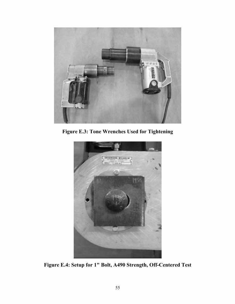
Figure E.3: Tone Wrenches Used for Tightening
Figure E.4: Setup for 1" Bolt, A490 Strength, Off-Centered Test


![Square, Hex, Heavy Hex, and Askew Head Bolts and …AN AMERICAN NATIONAL STANDARD ASME B18.2.1-2010 [Revision of ASME B18.2.1-1996 (R2005)] Square, Hex, Heavy Hex, and Askew Head Bolts](https://img.pdfslide.net/doc/110x75/5e8d84b0bce495059d77e136/square-hex-heavy-hex-and-askew-head-bolts-and-an-american-national-standard-asme.jpg)