Embed Size (px)
Citation preview
Effects of Hot Isostatic Pressure on Titanium Nitride Films
Deposited by Physical Vapor Deposition
M.J. Carbonari*, J.R. Martinelli
Energy and Nuclear Research Institute, Brazilian Nuclear Energy Commission,C.P. 11049, 05422-970 São Paulo - SP, Brazil
Received: November 14, 2000; Revised: June 23, 2001
Films of titanium nitride deposited by physical vapor deposition on 304 L stainless steelsubstrates were hot isostatic pressed (HIP) under 150 MPa at 550 °C. To study the effects of thistreatment on the microstructure of those films, X-ray diffraction analyses, Rutherford Backscatteringspectroscopy, scanning electron microscopy, and atomic force microscopy were performed. Surfacehardness, and roughness were also evaluated to characterize the TiN properties. The hot isostaticpressure leads to an increase of hardness for depths up to 0.1 µm and a crystallographic texturechange from (111) to (200). The original TiN golden color turned to red after the treatment. Anincrease of the grain size has been observed for hot isostatic pressed samples, but the stoichiometryof the TiN film was determined to be 1:1 by RBS. The microstructure observed by atomic forcemicroscopy indicated that the TiN film surface is smoother after the HIP treatment.
Keywords: Titanium nitride, PVD, HIP
1. Introduction
Hard films deposited by chemical vapor deposition(CVD) on metals have been used industrially since the 60’s.Physical vapor deposition (PVD) uses lower processingtemperatures compared to the ones needed for CVD1. Thefirst industrial use of titanium nitride films deposited byPVD on tools designed for cold forming processes wasreported in 19772. Films deposited by CVD and PVDusually improves the tribological properties of mechanicalcomponents, cutting tools, and they can also be used fordecorative purposes. In the PVD process, a metallic reac-tive component, for instance, solid titanium, replaces thegas media usually used in the CVD process1. The first stagein the PVD process involves the transport of ions, atoms,or molecules, to the top of the substrate. The second stageis the adsorption of these species by the substrate, or by thegrowing film, and diffusion over the surface, and finally,the incorporation of those species in the film. The last stageis the atomic diffusion into the bulk. The film depositiondepends on the process chamber geometry, target size, andgas pressure. The diffusion stage depends mainly on thesubstrate temperature. Since the incident species comefrom a limited number of directions, the film grain structuretends to be columnar3.
There are some unique differences in the microstructureand residual stresses of films deposited by PVD and CVD.High residual compression stress and fine grains originatedby the PVD process usually improve the hardness andtoughness.
Titanium nitride films usually have low friction coeffi-cient, high hardness, are high temperature resistant, andadhere well to several substrates4. Besides that, cuttingtools deposited with those films show improved machiningperformance, and wear and corrosion resistance5. Titaniumnitride films also show an attractive aesthetic appearancedue to their golden color.
2. Structural Zone ModelThe growth of TiN films happens in well defined re-
gions depending on the electrical potential applied to thesubstrate and the deposition temperature.
Mochvan e Demchishin6 were the first ones to classifythe microstructure and to identify three structural regionsdepending on the deposition temperature. In the regionnamed zone 1 (low temperatures), the microstructure con-sists of round-topped conic columns, and it is due to therelatively low atomic mobility. As the temperature is raised,diffusion becomes important in the film growth, and themicrostructure becomes columnar with parallel sides andsmooth topography. This region is named zone 2. If the
Materials Research, Vol. 4, No. 3, 163-168, 2001. © 2001
*e-mail: [email protected] apresentado no 14° CBECIMAT, Águas de São Pedro, Dezem-bro de 2000.
temperature is further raised, the microstructure gets theappearance of equiaxial grains and this region is namedzone 3. Latter on, Thornton7 suggested that the presence ofa gas phase during the deposition process could alter themodel proposed by Mochvan and Demchishin, and a newmicrostructure region was identified (named zone T) whichconsists of fibrous grains.
3. Phase Transformation
Below 882 °C titanium has a hexagonal close packedcrystalline structure (HCP) known as α-Ti. According tothe Ti-N phase diagram, by increasing the nitrogen concen-tration, the titanium lattice expands in order to accommo-date dissolved nit rogen atoms. The maximumconcentration of nitrogen that can be dissolved in the tita-nium lattice is 23 atomic % at 1050 °C, corresponding to aratio N/Ti = 0.3. For nitrogen concentrations around 33atomic %, and temperatures lower than 1050 °C, the Ti2Nphase with a body center tetragonal structure can be ob-served. For nitrogen concentrations around 37.5%, andtemperatures lower than 800 °C, the existence of Ti2N(α)or δ’-Ti2N phases is thermodynamically possible3,8-9.
The TiN phase, which has a face centered cubic struc-ture (FCC), also known as δ-TiN, can be found with non-stoichiometric compositions, TiNx, in the wide nitrogencompositional range of 40-55 at%8-9.
According to Wittmer10, phase transformations can beexplained considering that at low nitrogen pressures, nitro-gen atoms firstly occupy hexagonal interstitial sites of thetitanium hexagonal close packed structure (two sites perunit cell). Nitrogen atoms, being larger than the interstitialsites, give rise to expansion of the titanium lattice, raisingthe internal stresses of the crystalline lattice. When approxi-mately half of the interstitial sites are occupied, the latticedistortion leads to the transformation of HCP to FCC. Thisis possible considering that the ratio Ti:N is 2:1. Since theFCC unit cell has four atoms of titanium and eight tetrago-nal interstitial sites, the ratio 2:1 corresponds to the fillingof half of the FCC interstitial sites by nitrogen atoms. Byincreasing the nitrogen gas pressure, all interstitial sitestend to be filled out and titanium nitride is formed. If thenitrogen amount is further increased, nitrogen atoms willbe concentrated in the grain boundaries3.
The deposition of ceramic films has been intensivelyinvestigated in the last two decades. Hot isostatic pressure(HIP) can improve the consolidation of films deposited byPVD11. HIP is performed by using high pressures andtemperatures simultaneously. Pressure is applied by load-ing an inert gas or nitrogen. The commercial use of HIP isrelatively recent. New machines have been improved toraise the reliability of this technique, and a large volume ofmaterials have been already processed by this technique11.
In the present work the effects of HIP in the microstruc-ture of titanium nitride films deposited by PVD are stud-ied12.
4. Experimental
Titanium nitride films were deposited on 304 L stain-less steel substrates by the PVD process. The substrateswere cylindrical pellets 15 mm in diameter and 10 mmthick. The substrates were cut, and polished to a finish of600 mesh using SiC paper. Thirty-five specimen wereprepared for this work. The substrate was chosen on thebasis that deposition of TiN on stainless steel could be usedin orthopedic implants.
HIP was performed by using a Asea Brown BoveriAutoclave model QIH-3. Nitrogen was used as the load gassince the aim of this work was to increase the nitrogenconcentration in the titanium nitride film.
The HIP was performed by keeping the samples under150 MPa at 500 °C for 100 min. This specific thermal cyclewas chosen to avoid structural changes of the substrate. Noother cycles were tried on.
The surface roughness (Ra and RMS) was determinedby using a Atomic Force Microscope (AFM) Topometrixmodel Explorer. Measurements were performed on differ-ent areas of the film.
The film hardness was measured (Micro HardnessFisher), and a software known as Hart was used to fit thedepth profile curves. These measurements were performedby keeping the indenter perpendicularly to the film surface.
Rutherford Backscattering (RBS) was performed byusing a Van der Graff tandem accelerator (NEC - NationalElectrostatics Corp. model 5SDH) with He+ 2 MeV beam.Samples 5 mm2 were cut and placed in a sample-holder.This technique allows the determination of the Ti:N ratiothrough the scattering of energetic particles with energiesthat depend on the atomic weight and position of theelements.
X-ray diffraction was performed (Bruker AXS modeloD 8 Advance) by using Cu Kα radiation in the 2θ range of10° to 80° at 2° per minute to determine changes of thetexture caused by the heat treatment.
Scanning electron microscopy (SEM) was performedby using a SEM Philips model XL 30. Samples werepreviously prepared by mounting them with epoxy resin,grinding with 220, 300, 400, 600 e 1000 SiC paper, andpolishing with 6, 3 e 1 µm diamond pastes.
5. Results and Discussion
Titanium nitride films deposited by PVD are typicallygolden. After HIP, films turned red, what can be an indica-tion that changes in the crystalline plane orientation oc-curred. Possible oxygen contamination during the HIP
164 Carbonari & Martinelli Materials Research
process were checked by RBS and EDS, which could causeoxidation, but no evidences were found.
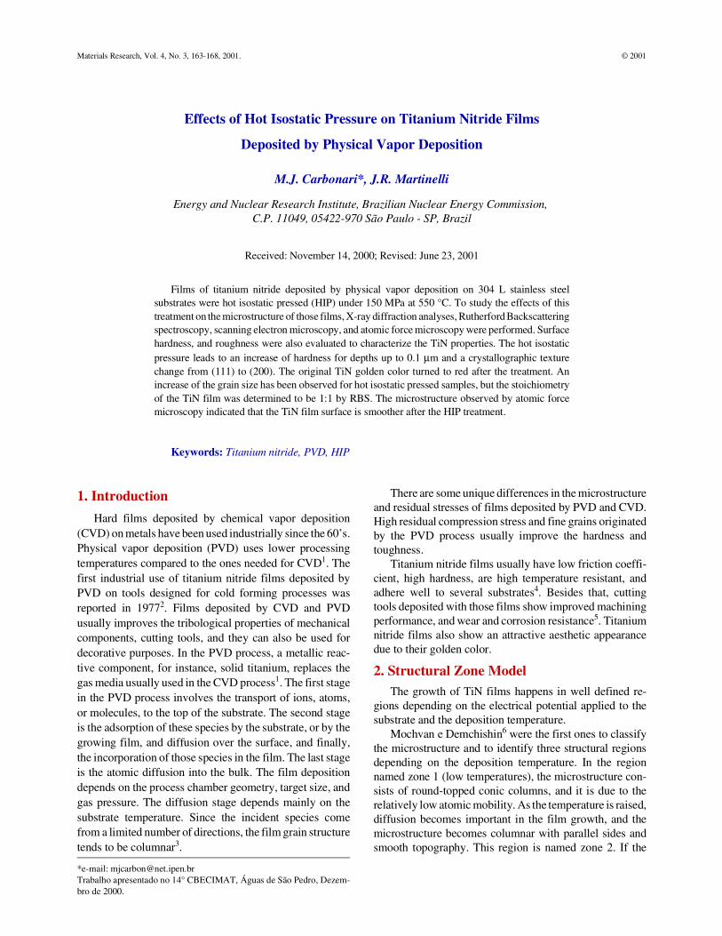
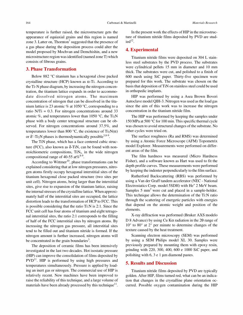
Figures 1 and 2 show the depth profile of the indenterpenetration as a function of the load applied to measure thehardness in samples with and without HIP treatment, fordifferent limits of maximum penetration (1 µm and 0.1 µmrespectively). Hardness values shown on the top of thefigures are related to the maximum depth reached by theindenter. Figure 1 shows that, for depths up to 1 µm, theloads to reach a certain depth are similar for both type ofsamples (with and without heat treatment). On the otherhand, Fig. 2 shows that in the region closest to the surface(maximum depth of 0.1 µm), the indenter loads to reach acertain depth depend on the heat treatment and the valuesare very apart. A large difference of hardness can also be
noticed for depths up to 0.1 µm (Fig. 2). For deeper regionshardness values are close, as shown in Fig. 1. Therefore, alarge variation of hardness was only found in the regionclosest to the surface (up to 0.1 µm) which could be causedby the nitrogen diffusion in the TiN film.
Table 1 shows the average values and the standarddeviation of Ra and RMS related to the surface roughnessdetermined by AFM. These values are relatively smaller forhot isostatic pressed samples.
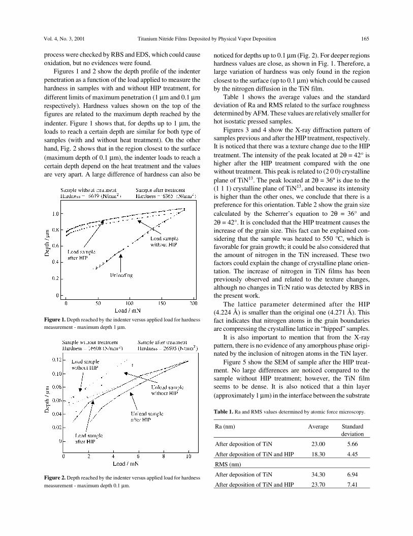
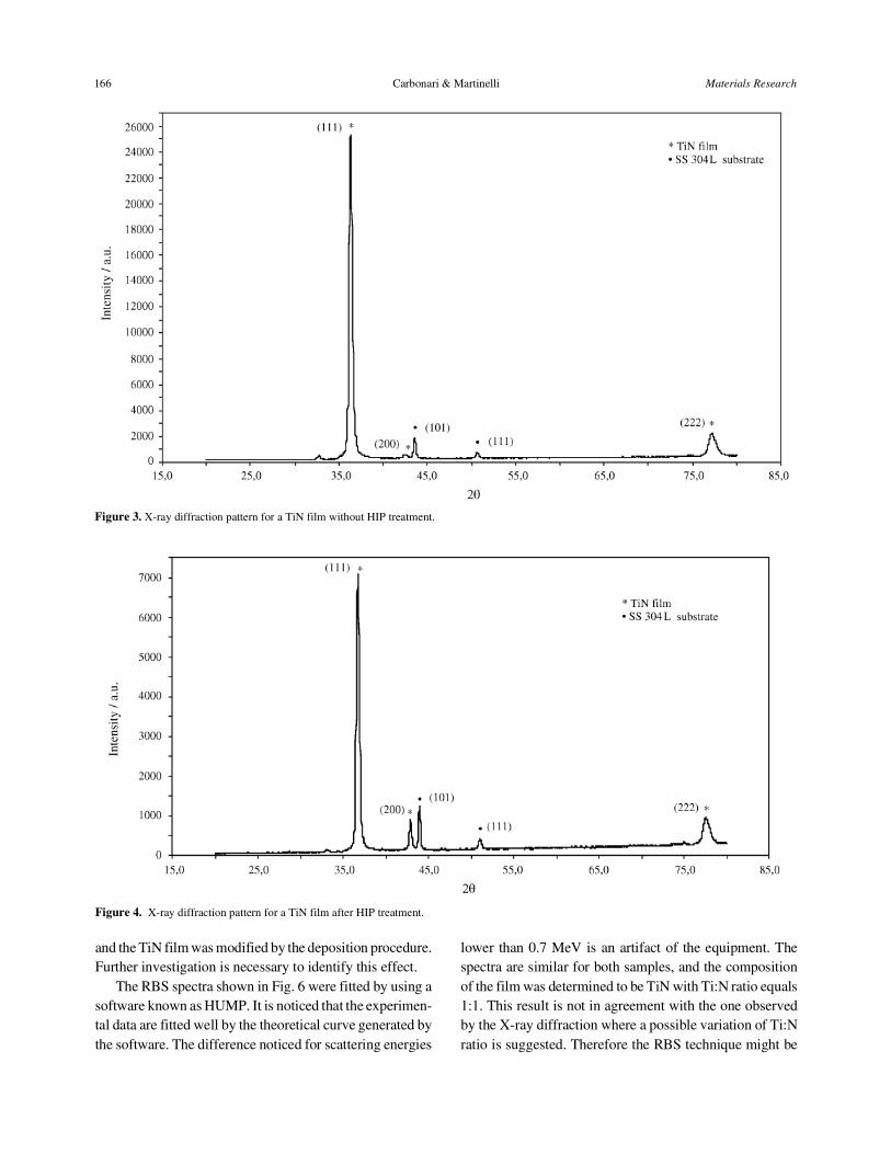
Figures 3 and 4 show the X-ray diffraction pattern ofsamples previous and after the HIP treatment, respectively.It is noticed that there was a texture change due to the HIPtreatment. The intensity of the peak located at 2θ = 42° ishigher after the HIP treatment compared with the onewithout treatment. This peak is related to (2 0 0) crystallineplane of TiN13. The peak located at 2θ = 36º is due to the(1 1 1) crystalline plane of TiN13, and because its intensityis higher than the other ones, we conclude that there is apreference for this orientation. Table 2 show the grain sizecalculated by the Scherrer’s equation to 2θ = 36° and2θ = 42°. It is concluded that the HIP treatment causes theincrease of the grain size. This fact can be explained con-sidering that the sample was heated to 550 °C, which isfavorable for grain growth; it could be also considered thatthe amount of nitrogen in the TiN increased. These twofactors could explain the change of crystalline plane orien-tation. The increase of nitrogen in TiN films has beenpreviously observed and related to the texture changes,although no changes in Ti:N ratio was detected by RBS inthe present work.
The lattice parameter determined after the HIP(4.224 Å) is smaller than the original one (4.271 Å). Thisfact indicates that nitrogen atoms in the grain boundariesare compressing the crystalline lattice in “hipped” samples.
It is also important to mention that from the X-raypattern, there is no evidence of any amorphous phase origi-nated by the inclusion of nitrogen atoms in the TiN layer.
Figure 5 show the SEM of sample after the HIP treat-ment. No large differences are noticed compared to thesample without HIP treatment; however, the TiN filmseems to be dense. It is also noticed that a thin layer(approximately 1 µm) in the interface between the substrate
Vol. 4, No. 3, 2001 Titanium Nitride Films Deposited by Physical Vapor Deposition 165
Figure 1. Depth reached by the indenter versus applied load for hardnessmeasurement - maximum depth 1 µm.
Figure 2. Depth reached by the indenter versus applied load for hardness
measurement - maximum depth 0.1 µm.
Table 1. Ra and RMS values determined by atomic force microscopy.
Ra (nm) Average Standarddeviation
After deposition of TiN 23.00 5.66
After deposition of TiN and HIP 18.30 4.45
RMS (nm)
After deposition of TiN 34.30 6.94
After deposition of TiN and HIP 23.70 7.41
and the TiN film was modified by the deposition procedure.Further investigation is necessary to identify this effect.
The RBS spectra shown in Fig. 6 were fitted by using asoftware known as HUMP. It is noticed that the experimen-tal data are fitted well by the theoretical curve generated bythe software. The difference noticed for scattering energies
lower than 0.7 MeV is an artifact of the equipment. Thespectra are similar for both samples, and the compositionof the film was determined to be TiN with Ti:N ratio equals1:1. This result is not in agreement with the one observedby the X-ray diffraction where a possible variation of Ti:Nratio is suggested. Therefore the RBS technique might be
Figure 3. X-ray diffraction pattern for a TiN film without HIP treatment.
Figure 4. X-ray diffraction pattern for a TiN film after HIP treatment.
166 Carbonari & Martinelli Materials Research
not enough accurate to indicate this variation, at least, inthe order of magnitude observed in the present work.
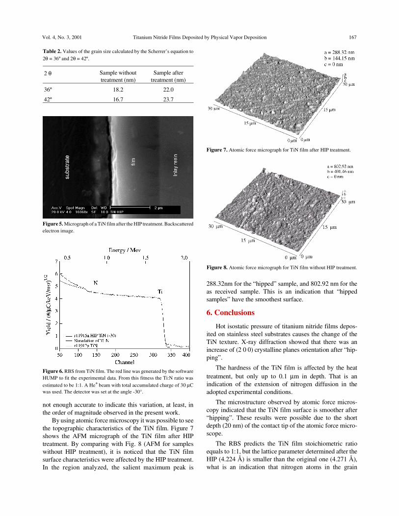
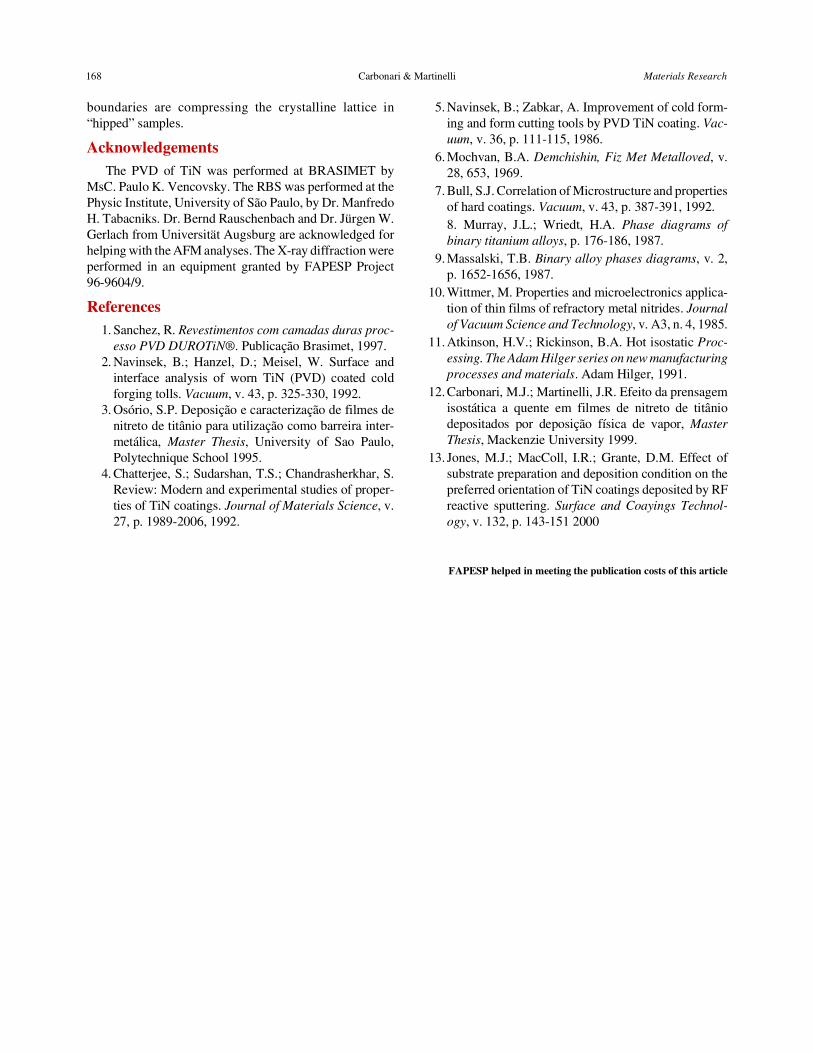
By using atomic force microscopy it was possible to seethe topographic characteristics of the TiN film. Figure 7shows the AFM micrograph of the TiN film after HIPtreatment. By comparing with Fig. 8 (AFM for sampleswithout HIP treatment), it is noticed that the TiN filmsurface characteristics were affected by the HIP treatment.In the region analyzed, the salient maximum peak is
288.32nm for the “hipped” sample, and 802.92 nm for theas received sample. This is an indication that “hippedsamples” have the smoothest surface.
6. Conclusions
Hot isostatic pressure of titanium nitride films depos-ited on stainless steel substrates causes the change of theTiN texture. X-ray diffraction showed that there was anincrease of (2 0 0) crystalline planes orientation after “hip-ping”.
The hardness of the TiN film is affected by the heattreatment, but only up to 0.1 µm in depth. That is anindication of the extension of nitrogen diffusion in theadopted experimental conditions.
The microstructure observed by atomic force micros-copy indicated that the TiN film surface is smoother after“hipping”. These results were possible due to the shortdepth (20 nm) of the contact tip of the atomic force micro-scope.
The RBS predicts the TiN film stoichiometric ratioequals to 1:1, but the lattice parameter determined after theHIP (4.224 Å) is smaller than the original one (4.271 Å),what is an indication that nitrogen atoms in the grain
Vol. 4, No. 3, 2001 Titanium Nitride Films Deposited by Physical Vapor Deposition 167
Figure 6. RBS from TiN film. The red line was generated by the softwareHUMP to fit the experimental data. From this fitness the Ti:N ratio wasestimated to be 1:1. A He+ beam with total accumulated charge of 30 µCwas used. The detector was set at the angle -30°.
Figure 5. Micrograph of a TiN film after the HIP treatment. Backscatteredelectron image.
Table 2. Values of the grain size calculated by the Scherrer’s equation to2θ = 36º and 2θ = 42º.
2 θ Sample withouttreatment (nm)
Sample aftertreatment (nm)
36º 18.2 22.0
42º 16.7 23.7
Figure 7. Atomic force micrograph for TiN film after HIP treatment.
Figure 8. Atomic force micrograph for TiN film without HIP treatment.
boundaries are compressing the crystalline lattice in“hipped” samples.
AcknowledgementsThe PVD of TiN was performed at BRASIMET by
MsC. Paulo K. Vencovsky. The RBS was performed at thePhysic Institute, University of São Paulo, by Dr. ManfredoH. Tabacniks. Dr. Bernd Rauschenbach and Dr. Jürgen W.Gerlach from Universität Augsburg are acknowledged forhelping with the AFM analyses. The X-ray diffraction wereperformed in an equipment granted by FAPESP Project96-9604/9.
References1. Sanchez, R. Revestimentos com camadas duras proc-
esso PVD DUROTiN®. Publicação Brasimet, 1997.2. Navinsek, B.; Hanzel, D.; Meisel, W. Surface and
interface analysis of worn TiN (PVD) coated coldforging tolls. Vacuum, v. 43, p. 325-330, 1992.
3. Osório, S.P. Deposição e caracterização de filmes denitreto de titânio para utilização como barreira inter-metálica, Master Thesis, University of Sao Paulo,Polytechnique School 1995.
4. Chatterjee, S.; Sudarshan, T.S.; Chandrasherkhar, S.Review: Modern and experimental studies of proper-ties of TiN coatings. Journal of Materials Science, v.27, p. 1989-2006, 1992.
5. Navinsek, B.; Zabkar, A. Improvement of cold form-ing and form cutting tools by PVD TiN coating. Vac-uum, v. 36, p. 111-115, 1986.
6. Mochvan, B.A. Demchishin, Fiz Met Metalloved, v.28, 653, 1969.
7. Bull, S.J. Correlation of Microstructure and propertiesof hard coatings. Vacuum, v. 43, p. 387-391, 1992.8. Murray, J.L.; Wriedt, H.A. Phase diagrams ofbinary titanium alloys, p. 176-186, 1987.
9. Massalski, T.B. Binary alloy phases diagrams, v. 2,p. 1652-1656, 1987.
10. Wittmer, M. Properties and microelectronics applica-tion of thin films of refractory metal nitrides. Journalof Vacuum Science and Technology, v. A3, n. 4, 1985.
11. Atkinson, H.V.; Rickinson, B.A. Hot isostatic Proc-essing. The Adam Hilger series on new manufacturingprocesses and materials. Adam Hilger, 1991.
12. Carbonari, M.J.; Martinelli, J.R. Efeito da prensagemisostática a quente em filmes de nitreto de titâniodepositados por deposição física de vapor, MasterThesis, Mackenzie University 1999.
13. Jones, M.J.; MacColl, I.R.; Grante, D.M. Effect ofsubstrate preparation and deposition condition on thepreferred orientation of TiN coatings deposited by RFreactive sputtering. Surface and Coayings Technol-ogy, v. 132, p. 143-151 2000
FAPESP helped in meeting the publication costs of this article
168 Carbonari & Martinelli Materials Research