Embed Size (px)
Citation preview

Effects of Implant Design and Occlusal Loadingon Bone Remodeling in Implant Supported Single Crown:
A Finite Element Study Montip Monstaporn1,2, Pimduen Rungsiyakull3, Chaiy Rungsiyakull4, Pattarapon Saigerdsri4, Celin Arce Urena5
1Graduate student, Department of Prosthodontics, Faculty of Dentistry, Chiang Mai University, Thailand2Sena Hospital, Thailand 3Department of Prosthodontics, Faculty of Dentistry, Chiang Mai University, Thailand. 4Department of Mechanical Engineering, Faculty of Engineering, Chiang Mai University, Thailand.5Department of Prosthodontics, Faculty of Dentistry, University of Alabama at Birmingham, USA.
Received: April 16, 2021 • Revised: May 17, 2021 • Accepted: May 27, 2021
Corresponding Author: Pimduen Rungsiyakull Assistant Professor, Department of Prosthodontics, Faculty of Dentistry, Chiang Mai University, Chiang Mai 50200, Thailand. (E-mail: [email protected])
Abstract
Objectives: This study explores the preliminary understanding of the biomechanics with respect to the effect of implant design and occlusal loading location on the mandibular bone remodeling of implant supported single crown.
Methods: Three different implant designs (standard, short, and mini implant) with different occlusal loadings including non-occlusal contact (area loaded) and occlusal contact (center and 2-mm offsets horizontally loaded) were used to explore the stresses and strains transferred from the ceramic crown to the peri-implant bone through the implant. A 200 N loading was applied at the center of the crown. A strain energy density obtained from a three-dimensional finite element analysis was used as the mechanical stimuli to drive cortical and cancellous bone remodeling over the first 12 months after implant placement.
Results: Different occlusal loading location had a significant effect on bone remodeling responses in terms of the change in the average peri-implant bone density and overall stress/strain distributions. The 2 mm-horizontally offsets loading presented the largest stresses, strains, strain energy density, bone density, compared with the other occlusal loading locations. Under the 2-mm horizontally offsets loading, the greatest remodeling rate was achieved in mini implant, followed by standard and short implant. In mini implant, an average peri-implant bone density in cortical was 1.94 g/cm3 and in cancellous bone was 1.14 g/cm3 after 12 months of bone remodeling. The remodel-ing rate was rapidly high in the first to the second month of loading and continuously decreased until 12 months.
Conclusions: Within the limitations of this study, The occlusal loading location appeared to play important role than the implant design. An increased occlusal loading offset affected bone remodeling activities. A mini implant had the fastest remodeling process when compared with the short and standard implants, resulting in more bone density and strength in the first few months of an implant healing time. However, the mini implant also had the highest stress at bone-implant contact that may decrease primary implant stability.
Keywords: bone remodeling, implant biomechanics, implant design, loading location, mini implant
Original Article

CM Dent J: Volume 42 Number 2 May-August 202184
Introduction Over the last three decades, since dental implants were introduced for treatment in both partial and com-pletely edentulous patients, a demand in this choice of treatment has increased consistently.(1) Long-term success rates have been reported as high as 95% for mandibular implants and 90% for maxillary implants.(2) Moreover, dental implants have proven to be successful for long-term oral rehabilitation. The initial treatment plans for implant dentistry should include the ideal implant size, based on biome-chanical and esthetic considerations. The size of the im-plant is usually determined by the existing bone volume in height, width, and length. Biomechanical load is depen-dent on two factors: the character of the applied force and the functional surface area over the load.(3) The implant size directly affects the functional surface area that dis-tributes a load transferred through the prosthesis. Many different implant designs are available, so the options depend upon the amount of bone available, the patient’s general health and restoration preference. Mini dental implants are one of the optimal modality for placement in the area with narrow bone width, atro-phic bone, inadequate interdental space, and proximity or convergent of adjacent tooth roots because of their small size, in addition, the procedure for placement is a flap-less surgery, being less complex than a standard implant placement. As a result, post-insertion patient irritation and soreness is significantly reduced. Moreover, mini dental implants can be immediately loaded, which differentiates them from standard dental implants that have a reco- very time of 3-4 months after placement.(4) Furthermore, mini dental implants are a highly efficient common treat-ment because they have removability of partial or com-plete dentures while supporting fixed partial dentures for orthodontic use.(5) One of the most useful treatments is to retain mandibular complete denture because mini implants are not required for bone grafting and the surgical proce-dure is simple. For long-term success, the peri-implant bone density should be type I or type II. However, a mini dental implant also has some limitation such as, limited scientific evidence long term survival, lessen fracture during placement, lack of parallelism between implants is less forgiving from 1-piece design and a reduction in resistance to occlusal loading.(6)
Various complicating factors make surgical implant place-ment in the posterior maxilla increasing the difficulty. For these reasons, a short dental implant is an alternative choice for the posterior maxilla and the posterior mandible to avoid morbidity and complications(7), such as limited visibility and access, poor quality of bone, pneumatization of maxillary sinus, and post-extraction bone resorption. Cannizzaro et al. determined after review that there were no complication differences between 10-mm standard im-plant and 8-mm short implant.(8) Furthermore, the success rate of short implants in the posterior maxilla is high at 98.9%.(9)
One of the key factors for the success rate of implant restoration is complete osseointegration, relating to the bone remodeling responses that affect wound healing after implant placement and measured by bone-implant contact (BIC).(10) Additionally, the type and geometry of the implant affect amount of the force distributed to peri-implant bone and bone remodeling in varying types of implant.(11) Bone remodeling is a functional process explained as a bone adapting itself after applying the load to the bone by apposition and resorption through external and internal morphology, resulting in changes of the biomechanical environment.(12) As a result, proper implant design and geometry could promote bone remodeling and shortening of wound healing time after implantation.(12)
The superstructural designs of dental implants affect the type and amount of force, stress, and strain transferred to the peri-implant bone.(13) Occlusal design can generally affect functional characteristics in the implant prostheses. A proper occlusal design is aimed to maximize functional occlusion while minimize loading at the bone-implant interface, lessening the wear on occlusal surface, and providing long-term of restoration and implant.(14)
Several factors should be considered for implant placement to be successful. One of an important determi-nant is related to occlusal loading. Two types of immediate loading have been described in previous studies. One is immediate occlusal loading, which refers to the use of a prosthesis seated the same day as the surgery in occlusal contact with the opposing arch.(15) An alternative method for avoiding occlusal contact in centric and eccentric occlusion, in order to reduce the early damages of me-chanical overload is the immediate non-occlusal loading. The non-occlusal loading (area loading) is a loading when

CM Dent J: Volume 42 Number 2 May-August 2021 85
implants are subjected to functional loads by the alimenta-ry bolus without occlusal contact with the antagonist.(16) In previous studies, the biological differences in peri-im-plant tissue responses between occlusal and non-occlusal loading were statistically insignificant in the bone-implant contact during early phases of osseointegration.(17,18) Moreover, Chrcanovic et al.(19) presented that occlusal and non-occlusal loading did not significantly affect the implant failure rates and marginal bone loss of an implant. Therefore, the modified prosthesis would still be involved in the masticatory process, but the mechanical loading stress is reduced.(20)
Overloading is a primary cause of dental implant failure. Since a peri-implant bone can tolerate vertical force more than horizontal force, the concept of horizontal fossa or “long centric” modifications in prosthetic restoration can diminish horizontal force that contributing to implant failure.(21) However, studies on the effect of different implant designs in relation to bone remodeling are limited. The purpose of this study was to analyze and compare the characteristics of stress, strain, and density distribution on peri-implant bone remodeling within 12 months between the three different implant designs with varying loading paterns and locations. Finite element analysis was used for bone remodeling simulations, providing the data for bone remodeling predictations, and eventually used as a guideline for implant planning before implant placement.(22-24) Many FEA studies of dental implants have shown that there are differences in stress and strain in implants depending on the type of loading, bone-implant interface, length, and diameter of implants presented by different colors; wherein each color represented a difference of stress around the peri-implant region.(25)
Material and Methods
Finite element model The three-dimensional model consists of three different implant designs, implant abutment, sectional bone, and all ceramic crown with horizontal flat 1.5 mm at central fossa. The mandibular bone section was divided into two segments: the outer part reprensented the cortical bone with an average 2-mm thickness 2 mm and the inner part represented the cancellous bone that was assumed to be
continuously bonded with a cortical bonepart. Implant models consist of three implant designs including, standard implant (PWplus CO., LTD., Nakorn Pratom, Thailand) with a diameter of 4.2 and length of 10 mm, mini implant (PWplus CO., LTD., Nakorn Pratom, Thailand) with a diameter of 2.75 mm and length of 10 mm (PWplus CO., LTD., Nakorn Pratom, Thailand) and length of 10 mm., and short implant (Novem CO., LTD., Nakorn Pratom, Thailand) with a diameter of 4.2 mm and length of 6 mm. The abutment selected for this study was a titanium abutment height 5.5 mm. (PWplus CO., LTD., Nakorn Pratom, Thailand) with height of 5.5 mm. placed onto the implant. The abutment-implant models were imported into SolidWork 2007 software and ceramic crown of lower first premolar with 30- degree cusp inclinations, height and width of 8 mm, and flat central fossa 1.5 mm in mesio-distal dimension. The element mesh was generated by using three-node linear tetrahedral elements with an average of 816,169, 337,324, and 411,045 nodes with 2,055,759, 1,814,380, and 2,328,846 elements in standard, mini, and short implant, respectively. The meshes were confirmed to have adequate accuracy and computing efficiency by a mesh independence study.(26) The 3D solid structures were converted into 3D-FE models to analyze remodeling response in buccolingual dimension. The bone-implant model was constructed by placing each design of implant at the center of the bone. Each implant was surrounded by 2- mm thickness of cortical bone and the implants were assumed to be fully bonded to cortical and cancellous bone. The FE analysis wasere performed, and all materials were persumed to be linearly elastic, homogenous, and isotropic. Properties of material, i.e., Young’s modulus and Poisson’s ratio, were obtained from the literature (Table 1).
Finite element analysis A mechanical load of 200 N was applied to the top of the crown at three different contacts and distances: non-occlusal contact (area loading), occlusal contact at center loading, and occlusal contact at 2-mm offsets horizontally loading from the center to buccal side for group 1, 2, and 3, respectively (Figure 1).(23,25,29) The load was applied perpendicular to the crown surface for

CM Dent J: Volume 42 Number 2 May-August 202186
Ca = 60 (month x g/cm5) for cortical bone and Cr = 120 (month x g/cm5) for cancellous bone and K = 0.000036 J/g/cm3.(37,38) The increasing time step (∆t) represents 1-month of bone remodeling. (Equation 1).
Equation 1
The relationship from the literature between Young’s modulus (E1 in GPa) and density (ρ in g/cm3) for the cortical bone as the equation 2(38)
Equation 2
The relationship from literature between Young’s modulus (E2 in GPa) and density (ρ in g/cm3) for the cancellous bone as the equation 3(39)
Equation 3
Figure 3 shows the formulae were processed for bone remodeling simulation in an ABAQUS. Each simulation represents 1-month for bone remodeling and forming for a period of 1-year (12 cycles) simulation.(23)
Results and Discussion This study analyzed the effect of different implant designs on bone remodeling over the duration of 12 months in terms of changes in stress, strain , SED, and density distribution around peri-implant bone at the bone-implant interface. Figure 4 shows the bone density distribution after 12 months of bone remodeling. There was a similar dis-tribution pattern in bone density for the three different implant designs, when applying the centered and area
Table 1: Material parameters
Materials Elastic modulus (GPa)
Poisson’s ratio
Titanium alloy(27) 110 0.35Ceramic(28) 63 0.33Cortical bone(27) 13.7 0.30cancellous bone(27) 1.37 0.30
Figure 1: Crown configuration with flat central fossa 1.5 mm in mesiodistal dimension and loading scenarios. (A) Non-occlusal loading (area loading) (B) Centered loading, and (C) 2-mm offfsets horizontally loading
A B C
standard, mini, and short implant (Group A, B, C). So, There are nine experimental groups from three loading scenarios and three implant designs.
Bone-remodeling algorithm The theories of bone remodeling state that bone apposition and resorption are composed of external surface modeling, where the bone is added and removed at the surfaces and internal modeling, which causes changes in bone densities.(30) Many researchers have studied this process in different bone types wherein the process was controlled by internal sensors of bones that sent signals for stimulating mechanical stimuli; finding that stress, strain, and strain energy desity (SED) is a high efficacy of mechanical stimulationus for bone remodeling in dental implant(31-33) that can be aultered from genetics, hor-mones, metabolism, and site-specific factors. Frost suggested that if there is low mechanical stimuli from homeostatic levels, either bone apposition and resorption will not occur. An equilibrium situation with an unchanged bone mass is called “lazy zone” where 200-2,500 micro-stains is the steady or balanced bone level in Figure 2. SED per unit apparent density is often taken as a mechanical stimulus for bone remodeling prediction in many literatures,(22,32,34-36) where U is the SED and ρ is the local mass density.(23)
The remodeling rate of apparent density is associated with the difference between the mechanical stimulus (S) and reference thresholds of bone remodeling,(23), where
Figure 2: Bone remodeling algorithm.
E1 = -23.93 + 24 ρ
E2 = 2.349ρ2.15

CM Dent J: Volume 42 Number 2 May-August 2021 87
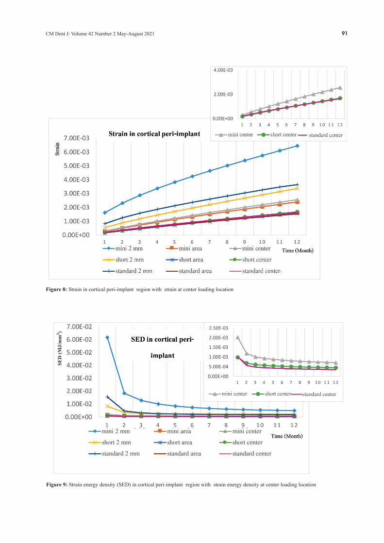
loading. However, it was found that there was a greater bone density distribution when the offset loading was applied. Figure 5 shows the changes in stress distribution after 12 months of bone remodeling. The highest stress was found in mini implant under 2-mm horizontally offsets loading location at the neck of implant in cortical peri-implant region (14.7 MPa) and the apex of implant in cancellous peri-implant region (2.09 MPa). There were a similar pattern of stress distribution when applying the area and centered loading. Thus, an eccentric loading played an important role significant part on bone remodeling activity. From a biomechani-cal point of view, the more offset loading were applied, the higher mechanical stimulation and bone remode- ling activity were induced(23,40) In cortical and cancellous peri-implant bone, the differences in stress and strain presented in three different implant designs under varying loading location were low. In cortical bone, the average stresses and strains were double to three times when applied 2-mm offsets load-ing, compared to that when applied the axial loading. The mechanical strain concentration at the peri-implant cortical bone represented bone apposition, especially in the first few months as a result of initial osseointegration and primary stability of the implant,(41) and the strain values increased continuously in both cortical and cancellous peri-implant bone represented the change in bone density during the healing time (Figure 8). The success of dental implant treatment depends on many factors, such as peri-implant bone density and strength of bone-implant interface.(40) After 12 months of remodeling, the highest stresses mostly developed in the cortical bone region, especially at the coronal aspect
(neck) of the dental implant. An increasing offset loading from the central fossa to the 2-mm horizontal offsets load-ing resulted in an increasing of the maximum stress in a cortical peri-implant as well as the cancellous peri-implant region (Figures 6-7), eventhough it was more uniform stress distribution pattern in the cancellous bone. Stress may be used to identify the damage that may occur at the bone-implant interface. The higher normal stress causes a higher risk of damage along the bone-implant contact area. From the study, the highest stress of mini-implant under the 2-mm offsets loading was approximately 14.7 MPa at the neck of an implant, which does not exceeded the average yield stress of cortical bone to withstand the overloading threshold of 35 MPa.(42) The changes of SED in the peri-implant cortical re-gion for different implant designs and loading locations were plotted in Figure 9. SED values decreased sharply within the first month for all implant designs under any loading locations. The SED values dropped about 60-70% when applied the 2-mm offsets load, while there was only 30-40% SED values dropped when applied the area and centered load. The equilibrium was generally archived after six to seven months. The highest SED value, which indicates the denser bone density, was found in cortical bone of mini-implant under the 2-mm offsets loading in this case. After 12 months of bone remodeling, the average peri-implant SED values when applied the centered load-ing were dropped by 69%, 58%, and 50% in mini, short, and standard implant, respectively. It is interesting to note that bone density and SED in a standard implant reached an equilibrium earlier than the other implant designs. Figure 10 represents the change of SED values in the cancellous region. When applying the 2-mm offsets loading, SED values of every implant design decreased
Figure 3: Flow chart of bone remodeling algorithm that represents 1-month cycle of remodeling simulation.

CM Dent J: Volume 42 Number 2 May-August 202188
Figure 4: The changes in density distribution within the cortical and cancellous peri-implant region after 12 months.

CM Dent J: Volume 42 Number 2 May-August 2021 89
Figure 5: The changes in stress distribution within the cortical and cancellous peri-implant region after 12 months.

CM Dent J: Volume 42 Number 2 May-August 202190
Figure 7: Stress in cancellous peri-implant region with stress at center loading location
Figure 6: Stress in cortical peri-implant region with stress at center lading location
CM Dent J: Volume 42 Number 2 May-August 2021 91
Figure 8: Strain in cortical peri-implant region with strain at center loading location
Figure 9: Strain energy density (SED) in cortical peri-implant region with strain energy density at center loading location
SED
(MJ/
mm
3 )

CM Dent J: Volume 42 Number 2 May-August 202192
Figure 10: Strain energy density(SED) in cancellous peri-implant region with strain energy density at center loading location
Figure 11: Density in cortical peri-implant region with density at center loading location
SED
(MJ/
mm
3 )

CM Dent J: Volume 42 Number 2 May-August 2021 93
Figure 12: Density in cancellous peri-implant region with density at center loading location
sharply within the first to second month, then con- tinuosly dropped by 10.4%, 7.35%, and 4.35% in the mini, short, and standard implant, respectively. On the contrary, when applying the centered and area loading, SED values increased sharply within the first to second month, then increased 14.1%, 9.28%, and 5.25% under area loading and increased 12.4%, 8.84%, and 4.16% under centered loading in mini, short, and standard implants, respectively. Figures 11-12 represent the change in bone density within the cortical and cancellous peri-implant bone. The magnitude of bone density increased over a period of time. Bone remodeling was affected by loading location, espe-cially when eccentric loading was applied. The increasing rate of bone density was very high during the first few months, 0 to 2, then it was slowly decreased. The greatest remodeling rate was achieved with the cortical bone of the mini-implant under the 2-mm horizon-tally offsets loading with an average peri-implant density of 1.94 g/cm3 after 12 months. As for standard and short implant under 2-mm offsets loading, the values of an average peri-implant density were 1.81 and 1.72 g/cm3,
respectively, which was just slightly lower than the maximum cortical bone density of 2 g/cm3 suggested in the literature.(39) The value of average peri-implant density implies that the greater offset loading, the denser cortical bone and faster remodeling rate. At the 2-mm offset loading, the eccentric flexural bending affected more on the SED, the bone density, and the bone remodeling values.(41) Figure 12 represents the bone density development in the peri-implant cancellous region, which exhibited a similar pattern to the bone seen in the cortical region. The cancellous bone density continued to increase until month 12 where the density of mini, short, and stan-dard implant under the 2-mm horizontal offsets loading location was 1.14, 1.11, and 1.08 g/cm3, respectively. These bone density values were closely to the values when applied load at the area and centered loading loca-tion. Such observations confirmed that the peri-implant cancellous bone is more responsive to any changes of the applied load, which consistently agrees with the bone density progression in the cancellous region.(23) The SED converged more quickly and achieved equilibrium after 2

CM Dent J: Volume 42 Number 2 May-August 202194
months, while the cancellous bone density reached equi-librium more slowly. This indicates that a little change in bone density could result in a great change in the Young’s modulus, finally contributing to the change in magnitude of SED and structural stiffness, and why SED approached equilibrium earlier. The effect of SED and bone density shows loading location plays more important role than the implant design. The crown design that had flat area at the central fossa allowed axial force to be transferred to the peri- implant region, resulted in more uniform bone remodeling responses. The crown design that allowed more bending moment, for example the 2-mm offsets loading with steep cusp inclination could produce a faster remodeling rate and greater density of bone. In general, bone turnover rate continuously remains up to 6-7 months to reach an equilibrium of healing period.(37,43,44) In regards to the implant diameter and length, the highest stress and strain values were recorded in the mini implant, followed by relatively close values between the standard and the short implants. The results showed that diameter plays a more important role than implant length, which is in agreement with other studies.(40,45) The reason might be because the mini implant had less bone con-tact volume at the implant-bone interface. The implant diameter has an influence on stress distribution along the bone-implant interface.(40) An increase in implant width increases the area over which forces are dissipated. Many reports indicated that an increase in the implant diameter decreased the maximum stress around the implant neck.(46-48)
In regards to implant design, mini implant has higher stress and bone density than standard and short implant because of the diffence in bone-implant contact area. The bone-implant contact area of mini implant was 790 mm2, while the bone implant contact area of short and standard implants were 1,630 and 1,500 mm2, respectively. The average bone density of mini, short, and standard implant designs under 2-mm offsets loading was 1.46, 1.34, and 1.37 g/cm3, respectively where results in the remodeling rate of mini-implant type was higher than other implant designs after 12 months. Under the different occlusal loading, the highest values in every parameters (stress, strain, SED, and density distribution) that were applied under the 2-mm horizontally offsets loading on every implant design were found in
mini, standard, and short implant, respectively while the area and center loading have similar values. Therefore, the eccentric loading is a significant part on remodeling activities. In a biomechanical point of view, the greater offset loading induced a higher level of stimulation in bone remodeling and resulting in bone deposition.(23)
It should be considered that there are some limitations in this study. The material properties, such as Young’s modulus and Poisson’s ratio were assumes to be homogenous, isotropic, and linear elastic for simplifying the interpretation, but the remodeling generated a hetero- genous bone density distribution.(49) This study deter-mined normal loading force and bone level. Moreover, the differentiations from the real situations such as, configura-tion of screws, implant-abutment connection, and cement types may influence the varied outcomes.(50) The model’s limitations regarding to the difference between the abutment-fixture connection designs were showed the similar trend for maximum stress and pattern of stress distribution and insignificance findings based on different implant-abutment connecting shapes.(51,52) Furthermore, the least amount of stress on the various areas of the peri-implant bone was exhibited, when the loads applied were close to the long axis of the implant.(53) However, FEAs is an effective computational tool that has been applied from the engineering field to dental implant biomechanics.(25) Loading location and implant design were the interested factor to study, while the other variables were controlled under the same conditions in all loading directions.
Conclusions The 3D computer modeling presented that a crown with different loading locations can affect the load trans-mission and bone remodeling in peri-implant bone more than the implant designs. The study suggests that higher off axis loading distance effects more changes in stress, strain, and strain energy density to peri-implant bone. The remodeling analysis presented that bone in the cancellous peri-implant bone has more biomechanical change than the cortical peri-implant bone region. A mini implant has the fastest remodeling process when compared with short and standard implant resulting in more bone density and strength in the first few months of an implant healing time. However, a mini implant also has the highest stress at bone-implant interface that may

CM Dent J: Volume 42 Number 2 May-August 2021 95
decrease primary implant stability. All implant designs (standard, short, and mini im-plant) with axial loading direction have been recommend-ed to reduce stress and strain transferred to the peri-im-plant bone region; however, it could compromise the bone remodeling rate and takes a longer period to increase bone density and healing time.
Acknowledgments The authors wish to thank Dr. Thanapat Sastraru-ji, a statistician at the Faculty of Dentistry, Chiang Mai University, for his advice in result interpretation. The authors also wish to thank Adjunct Professor Richard L. Wilson, Faculty Consultant at Chiang Mai University Faculty of Dentistry, Thailand, for his assistance in the preparation of the manuscript.
References1. Adell R, Eriksson B, Lekholm U, Brånemark PI, Jemt T. A
long-term follow-up study of osseointegrated implants in the treatment of totally edentulous jaws. Int J Oral Maxillofac Implants 1990; 5(4): 347-359.
2. Quirynen M, Naert I, van Steenberghe D, Nys L. A study of 589 consecutive implants supporting complete fixed pros-theses. Part I: Periodontal aspects. J Prosthet Dent 1992; 68(4): 655-663.
3. Bidez M, Misch C. Force transfer in implant dentistry: basic concepts and principles. J Oral Implantol 1992; 18(3): 264-274.
4. Chopra P, Chopra P, Grover HS. Mini dental implants-The same day implants. Int J Cont Dent 2011;2(3): 89-94.
5. Flanagan D, Mascolo A. The mini dental implant in fixed and removable prosthetics: a review. J Oral Implantol 2011; 37:123.
6. Bidra AS, Almas K. Mini implants for definitive prostho-dontic treatment: a systematic review. J Prosthet Dent 2013; 109(3): 156-164.
7. Morand M, Irinakis T. The challenge of implant therapy in the posterior maxilla: providing a rationale for the use of short implants. J Oral Implantol 2007; 33(5): 257-266.
8. Cannizzaro G, Felice P, Leone M, Viola P, Esposito M. Early loading of implants in the atrophic posterior maxilla: lateral sinus lift with autogenous bone and Bio-Oss versus crestal mini sinus lift and 8-mm hydroxyapatite-coated implants. A randomised controlled clinical trial. Eur J Oral Implantol 2009; 2(1): 25-38.
9. Misch CE, Steigenga J, Barboza E, Misch-Dietsh F, Cianciola LJ, Kazor C. Short dental implants in posterior partial edentulism: a multicenter retrospective 6-year case series study. J Periodontol 2006; 77(8): 1340-1347.
10. Davies JE. Understanding peri-implant endosseous healing. J Dent Educ 2003; 67(8): 932-949.
11. Frost HM. A 2003 update of bone physiology and Wolff's Law for clinicians. Angle Orthod 2004; 74(1): 3-15.
12. Lin D, Li Q, Li W, Swain M. Dental implant induced bone remodeling and associated algorithms. J Mech Behav Biomed Mater 2009; 2(5): 410-432.
13. Michaels GC, Carr AB, Larsen PE. Effect of prosthetic superstructure accuracy on the osteointegrated implant bone interface. Oral Surg Oral Med Oral Pathol Oral Radiol Endod 1997; 83(2): 198-205.
14. Kim Y, Oh TJ, Misch CE, Wang HL. Occlusal considerations in implant therapy: clinical guidelines with biomechanical rationale. Clin Oral Implants Res 2005; 16(1): 26-35.
15. Degidi M, Piattelli A. Immediate functional and non-func-tional loading of dental implants: A 2-to-60 month follow-up study of 646 titanium implants. J Periodontol 2003; 74(2): 225-241.
16. Giribone J, Morales M, Pedreira M, Russo P. Workshop 2-Loading protocols. Odontoestomatología 2017; 19.
17. Meyer U, Joos U, Mythili J, et al. Ultrastructural charac- terization of the implant/bone interface of immediately loaded dental implants. Biomaterials 2004; 25(10): 1959-1967.
18. Ghanavati F, Shayegh SS, Rahimi H, et al. The effects of loading time on osseointegration and new bone formation around dental implants: a histologic and histomorphometric study in dogs. J Periodontol 2006; 77(10): 1701-1707.
19. Chrcanovic BR, Albrektsson T, Wennerberg A. Immediate nonfunctional versus immediate functional loading and dental implant failure rates: a systematic review and meta-analysis. J Dent 2014; 42(9): 1052-1059.
20. Degidi M, Nardi D, Piattelli A. A comparison between immediate loading and immediate restoration in cases of partial posterior mandibular edentulism: a 3-year ran- domized clinical trial. Clin Oral Implants Res 2010; 21(7): 682-687.
21. Pankey LD, Mann AW. Oral rehabilitation: Part II. Recon-struction of the upper teeth using a functionally generated path technique. J Prosthet Dent 1960; 10(1): 151-162.
22. Rungsiyakull C, Chen J, Rungsiyakull P, Li W, Swain M, Li Q. Bone’s responses to different designs of implant- supported fixed partial dentures. Biomech Model Mechano-biol 2015; 14(2): 403-411.
23. Rungsiyakull C, Rungsiyakull P, Li Q, Li W, Swain M. Effects of occlusal inclination and loading on man- dibular bone remodeling: a finite element study. Int J Oral Maxillofac Implants 2011; 26(3): 527-537.
24. William K, Watson C, Murphy W, Scottt J, Gregory M, Sinobad D. Finite element analysis of fixed prostheses attached to osseointegrated implants. Quintessence Int 1990; 21(7): 563-570.
CM Dent J: Volume 42 Number 2 May-August 202196
25. Geng JP, Tan KB, Liu GR. Application of finite element analysis in implant dentistry: a review of the literature. J Prosthet Dent 2001; 85(6): 585-598.
26. Li W, Swain MV, Li Q, Steven GP. Towards automated 3D finite element modeling of direct fiber reinforced composite dental bridge. J Biomed Mater Res B Appl Biomater 2005; 74(1): 520-528.
27. Vaillancourt H, Pilliar R, McCammond D. Finite element analysis of crestal bone loss around porous-coated dental implants. J Appl Biomater 1995; 6(4): 267-282.
28. Archangelo CM, Rocha EP, Anchieta RB, et al. Influence of buccal cusp reduction when using porcelain laminate veneers in premolars. A comparative study using 3-D finite element analysis. J Prosthodont Res 2011; 55(4): 221-227.
29. Morneburg TR, Pröschel PA. Measurement of masticatory forces and implant loads: a methodologic clinical study. Int J Prosthodont 2002; 15(1): 20-27.
30. Cowin S, Van Buskirk W. Internal bone remodeling induced by a medullary pin. J Biomech 1978; 11(5): 269-275.
31. Huiskes R, Weinans H, Grootenboer H, Dalstra M, Fudala B, Slooff T. Adaptive bone-remodeling theory applied to prosthetic-design analysis. J Biomech 1987: 1135-1150.
32. Weinans H, Huiskes R, Grootenboer H. The behavior of adaptive bone-remodeling simulation models. J Biomech 1992; 25(12): 1425-1441.
33. Mellal A, Wiskott H, Botsis J, Scherrer S, Belser U. Stim-ulating effect of implant loading on surrounding bone: comparison of three numerical models and validation by in vivo data. Clin Oral Implants Res 2004; 15(2): 239-248.
34. Li J, Li H, Shi L, et al. A mathematical model for simulating the bone remodeling process under mechanical stimulus. Dent Mater 2007; 23(9): 1073-1078.
35. Chou H-Y, Jagodnik JJ, Müftü S. Predictions of bone remodeling around dental implant systems. J Biomech 2008; 41(6): 1365-1373.
36. Lin CL, Lin YH, Chang SH. Multi-factorial analysis of variables influencing the bone loss of an implant placed in the maxilla: prediction using FEA and SED bone remodeling algorithm. J Biomech 2010; 43(4): 644-651.
37. Lin D, Li Q, Li W, Duckmanton N, Swain M. Mandibular bone remodeling induced by dental implant. J Biomech 2010; 43(2): 287-293.
38. Rho J-Y, Hobatho M, Ashman R. Relations of mechanical properties to density and CT numbers in human bone. Med Eng Phys 1995; 17(5): 347-355.
39. O'Mahony AM, Williams JL, Katz JO, Spencer P. Aniso-tropic elastic properties of cancellous bone from a human edentulous mandible. Clin Oral Implants Res 2000; 11(5): 415-421.
40. Misch CE. Contemporary implant dentistry. Implant Dent 1999; 8(1): 90.
41. Rungsiyakull P, Rungsiyakull C, Appleyard R, Li Q, Swain M, Klineberg I. Loading of a single implant in simulated bone. Int J Prosthodont 2011; 24(2): 140-143.
42. Crupi V, Guglielmino E, La Rosa G, Vander Sloten J, Van Oosterwyck H. Numerical analysis of bone adaptation around an oral implant due to overload stress. Proc Inst Mech Eng H 2004; 218(6): 407-415.
43. Huang HM, Pan LC, Lee SY, Chiu CL, Fan KH, Ho KN. Assessing the implant/bone interface by using natural frequency analysis. Oral Surg Oral Med Oral Pathol Oral Radiol Endod 2000; 90(3): 285-291.
44. Huang HM, Lee SY, Yeh CY, Lin CT. Resonance frequency assessment of dental implant stability with various bone qualities: a numerical approach. Clin Oral Implants Res 2002; 13(1): 65-74.
45. Ding X, Liao SH, Zhu XH, Zhang XH, Zhang L. Effect of diameter and length on stress distribution of the alveolar crest around immediate loading implants. Clin Implant Dent Relat Res 2009; 11(4): 279-287.
46. Himmlova L, Kácovský A, Konvic̆ková S. Influence of implant length and diameter on stress distribution: a finite element analysis. J Prosthet Dent 2004; 91(1): 20-25.
47. Tuncelli B, Poyrazoglu E, Köylüoglu A, Tezcan S. Com-parison of load transfer by implant abutments of various diameters. Eur J Prosthodont Restor Dent 1997; 5(2): 79-83.
48. Goiato MC, Pesqueira AA, Dos Santos DM, Haddad MF, Moreno A. Photoelastic stress analysis in prosthetic implants of different diameters: mini, narrow, standard or wide. J Clin Diagn Res 2014; 8(9): 86-90.
49. Chen J, Rungsiyakull C, Li W, Chen Y, Swain M, Li Q. Multiscale design of surface morphological gradient for osseointegration. J Mech Behav Biomed Mater 2013; 20: 387-397.
50. Hansson S. A conical implant–abutment interface at the level of the marginal bone improves the distribution of stresses in the supporting bone: An axisymmetric finite element analysis. Clin Oral Implants Res 2003; 14(3): 286-293.
51. Cho SY, Huh YH, Park CJ, Cho LR. Three-dimensional finite element analysis of the stress distribution at the internal implant-abutment connection. Int J Periodontics Restorative Dent 2016; 36(3): 49-58.
52. Poovarodom P, Sae-Lee D, Suriyawanakul J. The 3D finite element analysis of stress distribution in implant supported single crown with different abutment designs. EASR 2018; 45(3): 240-250.
53. Balik A, Karatas MO, Keskin H. Effects of different abutment connection designs on the stress distribution around five different implants: a 3-dimensional finite element analysis. J Oral Implantol 2012; 38(1): 491-496.