Embed Size (px)
Citation preview
JMEPEG (1997) 6:61-68 �9 International
Effects of Post-Weld Heat Treatments on the Residual Stress and Mechanical Properties of Electron Beam Welded SAE 4130 Steel Plates
C.C. Huang, Y.C. Pan, and T.H. Chuang
The distribution of the residual stresses of electron beam welded SAE 4130 and the effect of stress relief after various post-weld heat treatments (PWHT) were measured using X-ray diffraction. The mechani- cal properties and microstructure were also examined. Experimental results show that the tensile resid- ual stress increased with the heat input of the electron beam. Most of the residual stresses were relieved by the PWHT at 530 ~ for 2 h followed by furnace cooling to 50 *C. The strength of the welds decreased slightly, and the elongation of the welds increased after PWHT.
Keywords
electron beam welding, heat treatment, post-weld treatment, residual stress
1, Introduction
ELECTRON BEAM welding (EBW) is a high-energy beam welding process. This process utilizes a very high-intensity beam as the power source for welding and has very high pene- trating power that a conventional heat source cannot achieve. Because of the extremely concentrated heat source, EBW can produce welds much deeper and narrower than arc welds. In ad- dition to a high depth-to-width ratio, low heat input and mini- mum distortion of the weld are advantages of EBW.
During welding, thermal stresses occur due to local heating. Residual stresses in a single-pass weld are produced by the re- sistance of the metal plate to the contraction of the weld. Resid- ual stresses and distortion result after welding and cause mismatching and cracking. In many cases, residual stresses don ' t cause cracking directly but promote fracturing through fatigue, hydrogen cracking, and stress corrosion. A thorough understanding of the magnitude and distribution of residual stresses can be used to increase the reliability of the structure. Therefore, measurement of residual stresses resulting from various welding parameters is important.
Many methods are used to measure residual stresses, such as stress relief, x-ray diffraction (XRD), ultrasound, and the elec- tromagnetic method (including Barkhausen). XRD is the most widely used nondestructive method. The principle is that when a metal is under stress, the resultant elastic strains cause the spacings of atomic planes in the metallic crystal structure to be changed (Ref 1). XRD can measure the interplanar atomic spacing, and from this quantity the stress can be evaluated. Three principal XRD techniques are used for stress measure- ment: the single-exposure technique, double-exposure tech- nique, and sin 2 ~ method (Ref 2). The single-exposure technique requires at least two independent x-ray detectors that
C.C. Huang and T.H. Chuang, Institute of Materials Science and En- gineering, National Taiwan University, Taipei, Taiwan, R.O.C.; and Y.C. Pan, Chung Shan Institute of Science and Technology, Lungtan, Taoyuan, Taiwan, R.O.C.
can be operated simultaneously. The last two require reposi- tioning of the stress-measuring device or the specimen during the process of performing stress measurement. The sin 2 method is a multi-exposure technique used to promote preci- sion.
Many examples have been given of the application of XRD to measurement of residual stress. Dolle used XRD to measure three-dimensional residual stress states to study the effect of grinding on Armco iron and a medium-carbon steel (Ref 3). Ruud used XRD to measure the residual stress on the inside sur- faces of stainless steel pipe weldments (Ref 4). He also used XRD to measure the three-dimensional residual stress field in thick multi-pass steel weldments (Ref 5). Nakayama evaluated the residual stresses in cold-rolled 5083 aluminum alloy by means of XRD (Ref 6). Lu measured the residual stresses for various welding methods using step-by-step hole drilling and XRD (Ref 7). Eigenmann used XRD to measure the residual stresses in thin chromiun coatings on steel (Ref 8). Even the re- sidual stresses of ceramics can be measured by means of XRD (Ref 9).
Residual stresses resulting from welding can be reduced by post-weld heat treatment (PWHT). This result is attributed to the decrease of crystal defects (vacancies and dislocations) and the change of the microstructure. In the present work, residual
I F"-
8 0 m m
=L Fig. 1
Weld fusion line
Rolling Direction
,Y
13L
-" (~T
120 mm ~1
1 I I
Schematic illustration of the specimen
X
2 . 4 m m
Journal of Materials Engineering and Performance Volume 6(1) February 1997--451

stresses in specimens after EBW under various conditions were measured using XRD. The effects of PWHT on the stress relief and the mechanical properties of electron beam welds were also examined.
2. Experimental
The welding specimens were made from SAE 4130 steel plates. The chemical composition of the as-received specimens (wt%) was 0.31 C, 0.50 Mn, 0.91 Cr, 0.20 Mo, 0.30 Si, 0.040 S, 0.035 P, and bal Fe. Representive mechanical properties of the material are shown in Table 1. The dimensions of specimens were 120 mm x 80 mm x 2.4 mm, as shown in Fig. 1. The specimens were welded by means of EBW. The fusion lines of all the weldments were perpendicular to the rolling direction (Fig. 1). EBW was performed under a vacuum of 1 x 10 -4 torr, with a fixed acceleration voltage of 50 kV and a gun-to-work distance of 53.0 cm. The beam focal point of the electron beam
T a b l e 1 M e c h a n i c a l p r o p e r t i e s o f t h e a s - r e c e i v e d s p e c i m e n s
Property Rolling direction Transverse direction
Tensile strength, kg/mrn 2 60. l 58.7 Yield strength, kg/mm 2 37.7 34.5 Elongation, % 28.7 26.3
T a b l e 2 E l e c t r o n beam welding c o n d i t i o n s
Parameter EBW1 EBW2 EBW3
welds was stationed 0.2 mm above the work surfaces. The welding conditions are shown in Table 2.
Stress analyses were performed by using a proto XRD-1000 diffractometer with one x-ray tube and two position-sensitive scintillation detectors (PSSD) (Ref 10). It can be operated us- ing the single-exposure technique, double-exposure technique, or multi-exposure technique. The geometrical relationship of
Voltage, kV 50 50 50 Current, mA 90 60 35 Power, kW 4.5 3 1.75 Welding speed, 2032 1524 10l 6
mm/min Energy, kJ/nma 0.1333 0.118 0.103
Note: The gun-to-work distance of EBW was 530 ram.
Counter
Specimen Surface
N S i i i
. . . . . . N v l
I - - _ " , ' A I " ' -
Y I "'" cq = 90 - O~ 1 ,S0~ o , ' ~ ~ ' / ~ . . ~ R R a2= 90-02 I A0 = cq - a~
', ," w2= t3+c~ E
Fig. 2 An illustration of the single-exposure technique. See Eq 1 and 2 for definition of symbols.
Fig. 3 Metallographs of the weld metal for: (a) EBW 1, (b) EBW2, (c) EBW3
62--Volume 6(1) February 1997 Journal of Materials Engineering and Performance

the single-exposure technique is shown in Fig. 2. For the sin- gle-exposure technique, the residual stresses are calculated from:
E [ ( R - L ) + (SoR - SOL)]
Oq, = 4R0(1 + v)sin20sin213 (Eq 1)
where E is Young ' s modulus, v is Poisson ' s ratio, R 0 is the distance between the counter and the specimen surface, 13 is the angle between the normal of the specimen surface and the x-ray tube, R and L are the distances between the diffrac- tion lines and the edges of the counters, and SOR and SOL are the arc lengths from the incident beam to the inside edges of the counters.
Fig. 4 Metallographs of the HAZ for: (a) EBW1, (b) EBW2, (c) EBW3
Fig. 5 Metallographs of the transition region between the HAZ and the base metal for: (a) EBW1, (b) EBW2, (c) EBW3
Journal of Materials Engineering and Performance Volume 6(1) February 1 9 9 7 ~ 3

For the double-exposure technique, the residual stresses can be calculated from the difference of the two diffraction angles, A0:
E cot 0A0 c ~ = ( l + v ) sin2~ (Eq2)
where 0 is the diffraction angle and ~ is the angle between the normal of the lattice plane (Np) and that of the specimen surface
(Ns). The multi-exposure technique is used to promote precision.
Measurements are made at a number of angles rather than at only one. Equation 2 can be rewritten as:
(1 + v)6~ A0 = sin2~ (Eq 3)
E cot 0
Values of A0 are plotted against sin2~, and the stress ~ is de- rived from the slope of the line. The more points there are, the more precisely the line will be established.
In the present work, the multi-exposure technique was used for stress measurement. Measurements were made with CrK a radiation to examine the [211] Bragg reflection plane and ob- tain a diffraction line at 20 = 156 ~ for the unstressed condition. CrKc~ was excited at 25 kV and 5 mA. Eight [3 tilts were exam- ined : +2 ~ +10 ~ +20 ~ and +45 ~ The values used for the other constants were R 0 --- 40 ram, E/(1 + v) = 156,000 MPa. The stress measurements were conducted along the transverse line passing through the weld center (the x axis in Fig. 1) and the longitudinal line parallel to the weld edge. Because the speci- mens were semisymmetric, only the stresses of the right halves were measured.
In order to evaluate the effect of PWHT on the welding re- sidual stresses relief, the welded specimens were heated to 320 and 530 ~ for 2 h and then furnace cooled to 50 ~ The resid- ual stresses of the PWHT specimens were measured following the same process. The welded specimens were then sectioned and prepared for metallographic inspections and microhard- ness measurements. The tensile properties of the welds were determined at room temperature using an MTS machine. Ten- sile specimens were made in accordance with ASTM E8M-93 with a gage length of 25 mm.
Fig. 6 Metallographs of the weld metal for: (a) EBW 1, (b) EBW2, (c) EBW3 after PWHT a1320 ~ for 2 h
3. Results and Discussion
The weldments of the as-welded SAE 4130 steel possessed a coarse lath martensite structure, as shown in Fig. 3. The struc- tures of the heat-affected zones (HAZ) are shown in Fig. 4. All of them were fine-grain martensite containing solid solutions of ~-Fe. The structure of the transition region between the base metal and HAZ was a mixture of fine-grain martensite which contained solid solutions of t~-Fe and retained ferrite, as shown in Fig. 5. The metallographs of the electron beam welds under various weld conditions were similar to one another. The struc- ture of the welds transformed to tempered martensite after both PWHTs (at 320 and 530 ~ are shown in Fig. 6 and 7, respec- tively. As the temperature of PWHT increased, the precipita- tion of a-Fe also increased.
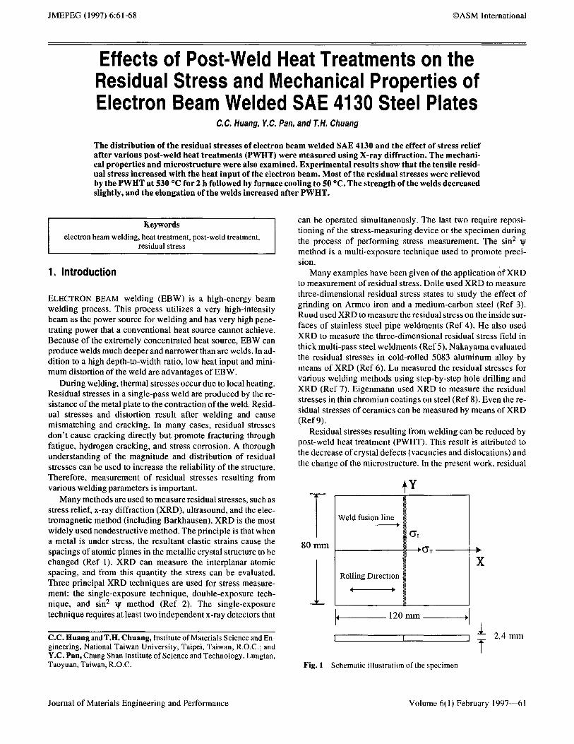
The stresses measured in the welds were the longitudinal re- sidual stress c~ L and the transverse residual stress CT, as shown in Fig. I. Figure 8(a) presents the residual stresses along an axis perpendicular to the weld measured on the surfaces of the EBW specimens under different welding conditions. The sequence of heat input for various weld conditions is: EBW1 > EBW2 > EBW3. Figure 8(a) also shows that the sequence of t~ L in the
64--Volume 6( 1 )Fcbruary 1997 Journal of Materials Engineering and Performance
tension zone of the welds corresponded to the sequence of heat input: EBW1 > EBW2 > EBW3. This result implies that c L in the tension zone is proportionally related to the heat input. Not only cr L, but also OT, taken 1 cm from the weld center line, was converted into compressive stresses. From Fig. 8(a), it can also be seen that (5 T was far less than ~L in the tension zone. How-
ever, there was no obvious relation between c T and heat input for the three specimens.
The residual stress distributions along the line parallel to the weld fusion line and close to the weld edge for the EBW speci- mens are shown in Fig. 8(b). The longitudinal residual stresses were nearly constant in the middle sections of the welds and were reduced near the ends of the welds. The transverse resid- ual stresses were very small in the middle sections of the welds and were converted into compressive stresses near the ends of
Fig. 7 Metallographs of the weld metal for: (a) EBWI, (b) EBW2, (c) EBW3 after PWHT at 530 ~ for 2 h
40 ~ O" T O'L
x\ - . - a EBw2 2O W3
..~ -20
~40
I I I I ( a ) 0 1 2 3 4 5
Distance from weld center line(cm)
40
G"
r~
N -2o
--40 .L ,
I 0 1 2 3
Distance from center of plate(cm) Fig. 8 The distribution of residual stresses along: (a) the trans- verse line passing through the weld center and (b) the longitudi- nal line parallel and close to the weld edge for electron beam welds
Journal of Materials Engineering and Performance Volume 6(1) February 1997----65

the welds. All the longitudinal residual stresses of the three specimens were larger than their transverse residual stresses. The quanti tat ive sequence o f (YL also corresponded to the se- quence o f heat input. In the middle sections of the welds, the quantitative sequence of O" T for various weld condit ions was similar to that o f c L. Near the ends of the welds, ~T was con- verted into compress ive stresses, and the sequence of (YT was reversed.
The distributions o f the residual stresses for the specimens after P W H T are shown in Fig. 9 and 10. For comparison, the stresses of the unwelded specimens are also presented. The re- sidual stresses were partially re l ieved after P W H T at 320 ~ as shown in Fig. 9. The G L in the tension zone as shown in Fig. 9(a) and the (YL as shown in Fig. 9(b) decreased, but they were still tensile stresses. Since the magnitude o f (YT for the as- welded specimen was small, the variation o f o T after PWHT at
4 0 -
E .~ 2 0 -
r~ o O -
r~
"~ -20 - "3 0
-40 -
O" T O" L
- - e - - O EBW 2
- ~ - - -,~ - ~ L D E D
(a)
I I I I 1 2 3 4
Distance from center of plate (cm)
40-
t"q
. ~ 2 0 -
o O - .lu
% "~ -20 - 0
-40 -
(YT O'L
+ 0 EBW 1
- 4 F - - - G - UNWELDED
~ ' ~ . - - ~ . . . . . . ~ ' ~ - "~ 0
(a)
I I I I l 2 3 4
Distance from w e l d center line (cm)
4 0 -
t 'q E
O-
"~ -20 - "3 0
-40 -
Fig. 9
~ T ~ L ---e--- 0 EBW 2
- - ~ - - < ' - UNWELDED ( b )
I I I 1 2 3
Distance from weld center line (cm)
The distribution of residual stresses along: (a) the trans- verse line passing through the weld center and (b) the longitudi- nal line parallel and close to the weld edge for specimens after PWHT at 320 ~ for 2 h
40
t',l
. ~ 20
o~ o 0
"~ -20 "3 0
-40 -
O" T (3" L
o EBw (b) - -O- - - "Q" - ~ L D E D
I I I 1 2 3
Distance from center of plate (cm)
The distribution of residual stresses along: (a) the Fig. 10 transverse line passing through the weld center and (b) the longi- tudinal line parallel and close to the weld edge for specimens af- ter PWHT at 530 ~ for 2 h
66---Volume 6(1) February 1997 Journal of Materials Engineering and Performance

320 ~ was not obvious. The stress rel ief effect was complete after P W H T at 530 ~ as shown in Fig. 10. Fig. 10(a) shows that there were no tensile residual stresses in the original ten- sion zone. The magnitudes o f (YT and (YL were close to those of the unwelded specimen, as shown in Fig. 10(b). The mechani- cal properties of the welds before and after various PWHTs are summarized in Table 3. For comparison, the mechanical prop- erties of the base metal are also listed in the table. It seems that the strength of the as-welded specimens decreased slightly and that the elongation increased as the heat input of EBW in- creased. The yield strength o f the welds increased after PWHT at 320 ~ but that of the welds decreased as the temperature of P W H T increased to 530 ~ In order to compare the differences among the mechanical properties for various PWHTs, Table 4 and Fig. 11 are given. The loss o f yield strength decreased when the temperature of the PWHTs increased, as shown in Fig. 1 l(a). The jo int ef f ic iency was scarcely different after P W H T at 320 ~ but it increased after P W H T at 530 ~ as shown in Fig. 11 (b). The loss of e longat ion was reduced as the
(a)
temperature of P W H T increased, as shown in Fig. 1 l(c). It is obvious that the mechanical properties of the welds could be improved after PWHTs , and that the improvement effect for P W H T at 530 ~ was better than that at 320 ~
The microhardness measurements on the as-welded and pos t -weld heat treated EBW specimens are shown in Fig. 12. All o f the microhardness profiles are similar. Since the struc- ture of the welds was martensite, the hardness o f the welds was much larger than that o f the base metal. There was a drastic drop in hardness for the weld across the HAZ. After P W H T at 320 ~ the hardness o f the welds obviously decreased and that o f the base metal decreased slightly. After P W H T at 530 ~ the hardness of the welds decreased further. The decrease of hard- ness in the weld region was obviously attributable to the change
Table 3 Mechanical properties of the welds after various PWTHs
YS, UTS, Elongation, PWHT kg/mm z kg/mm 2 %
As-welded Base 37.7 60.1 28.7 EBW1 32.5 51.4 20.2 EBW2 32.1 51.0 20.8 EBW3 31.8 50.6 21.6
320 ~ 2 h, F.C. Base 37.3 59.8 29.2 EBWI 34.3 51.0 23.4 EBW2 34.2 50.7 24.0 EBW3 34.0 50.3 24.6
530 ~ 2 h, F.C. Base 34.8 56.9 30.2 EBWI 32 9 50 3 24.8 EBW2 32.6 49.3 25.2 EBW3 32.2 49.0 25.6
Note: All specimens were tensile fractured in the base metal. YS, yield strength; UTS, ultimate tensile strength. F.C. is furnace cooling to 50 ~
(b)
(c)
Fig. 11 Comparisons of the mechamcal properties for as- welded specimens, PWHT at 320 ~ (PWHT-320) or 530 ~ (PWHT-530). (a) Loss of yield strength. (b) Joint efficiency. (c) Loss of elongation
Table 4 The loss of mechanical properties for the welds after various PWItTs
LossofYS, Lossofelongation, Jointefficiency(a), PWHT % % %
As-welded EBW1 13.8 29.6 85.5 EBW2 14.9 27.5 84.9 EBW3 15.6 24.7 84.2
320 ~ 2 h, F.C. EBWI 8.0 19.9 85.3 EBW2 8.3 17.8 84.8 EBW3 8.8 15.8 84.1
530 ~ 2 h, F.C. EBW1 5.5 17 9 88.4 EBW2 6.3 16.6 86 6 EBW3 7.5 15.2 86.1
(a) Ultimate tensile strength of the weld/ultimate tensile strength of the base metal. YS, yield strength. F.C. is furnace cooling to 50 ~
Journal of Materials Engineering and Performance Volume 6(1) February 1997---67

600
500
~ 4 0 0
~ 300
200
1 0 0
EBW 1 AS-WELDED PVVHT-320 WELD
BASE METAL
(a) I I I I I I I
-4 -3 -2 -1 0 l 2 3 D i s t a n c e f i o m w e l d cen te r l m e (nma)
6 0 0 [ EBW 2 ~ AS-WELDED
[ - ~ r ~ PWHT-320 WELD
,oo_ 40o ~ 3o0 ~ 3oo-
E BASE 200 METAL
1 0 0 ( b )
-4 -3 -2 -1 0 1 2 3 4 D i s t a n c e f r o m w e l d c e n t e r l i ne (n~m)
6 0 0 EBW 3
20O - J ~ ~ BASE
1oo (c) I I I 1 [ I I I
-4 -3 -2 - 0 1 2 3 D i s t a n c e firom w e l d cen te r l ine ( m m )
Fig. 12 Microhardness profiles on as-welded specimens, PWHT at 320 ~ (PWHT-320) or 530 ~ (PWHT-530). (a) EBWI. (b) EBW2. (c) EBW3
of structure from coarse lath martensite to tempered martensite after PWHT.
tributed to the change of microstructure in the weldments from coarse lath martensite to tempered martensite.
4. Conclusions
There were very narrow tension zones along the transverse direction for the EBW specimens. With the increase of the heat input of the electron beam weld, the O" L in the tension zone along the line perpendicular to the weld and passing through the weld center was larger. There were similar results for (~L and o T along the line parallel to the weld fusion line and close to the weld edge for the electron beam welds. As the tempera- ture of PWHT increased from 320 to 530 ~ the effect of stress relief became more obvious. Heat treatment at 530 ~ for 2 h and furnace cooling to 50 ~ could most effectively relieve the residual stresses of the EBW specimens. Corresponding to the stress-relief effect, the mechanical properties were improved. Although the strength of the welds decreased slightly, the elon- gation of the welds obviously increased after PWHT. PWHT also caused the hardness of the welds to decrease. The effect of PWHT on the residual stress and mechanical properties was at-
References 1. C.S. Choi, H.J. Prask, and S.F. Trovino, Journal of Applied Crys-
tallography, Vol 12, 1979, p 327 2. Residual Stresses Measurement by X-Ray Diffraction, 2nd ed.,
SAE J784a, Society of Automotive Engineers, 1971, p 17-24 3. H. Dolle and J.B. Cohen, Metall. Trans., Vol IlA, 1980, p 159-
164 4. C.O. Ruud, P.S. DiMascio, and D.M. Melcher, ExperimentalMe-
chanics, Vol 24 (No. 2), 1984, p 162-168 5. C.O. Ruud, R.N. Pangborn, P.S. DiMascio, and D.J. Snoha, Jour-
nal of Pressure Vessel Technology, Vol 107, 1985, p 185-191 6. Y. Nakayama, T. Takaai, and S. Kimura, Materials Tractions,
Vol 34 (No. 6), 1993, p 496-503 7. J. Lu, C. Bouhelier, H.P. Lieurade, D. Baralle, B. Miege, and J. F.
Flavenot, Welding in the World, Vo133 (No. 2), 1994, p 118-128 8. B. Eigenmann, B. Scholtes, and E. Macherauch, Surface Engi-
neering, Vol 7 (No. 3), 1991, p 221- 224 9. C.O. Ruud and C.P. Gazzara, J. Am. Ceram. Soc., Vo168 (No. 2),
1985, p 67-68 10. C.O. Ruud, hldustrial Research and Development, Jan 1983, p
84-87
68---Volume 6(1) February 1997 Journal of Materials Engineering and Performance